EP1050488A2 - Ensemble de conteneurs et procédé de solidarisation des conteneurs - Google Patents
Ensemble de conteneurs et procédé de solidarisation des conteneurs Download PDFInfo
- Publication number
- EP1050488A2 EP1050488A2 EP00105841A EP00105841A EP1050488A2 EP 1050488 A2 EP1050488 A2 EP 1050488A2 EP 00105841 A EP00105841 A EP 00105841A EP 00105841 A EP00105841 A EP 00105841A EP 1050488 A2 EP1050488 A2 EP 1050488A2
- Authority
- EP
- European Patent Office
- Prior art keywords
- profiles
- container
- group according
- profile
- sealing
- Prior art date
- Legal status (The legal status is an assumption and is not a legal conclusion. Google has not performed a legal analysis and makes no representation as to the accuracy of the status listed.)
- Withdrawn
Links
- 238000000034 method Methods 0.000 title claims description 10
- 238000007789 sealing Methods 0.000 claims abstract description 115
- 230000000295 complement effect Effects 0.000 claims abstract description 12
- 230000007613 environmental effect Effects 0.000 claims description 15
- 238000013459 approach Methods 0.000 claims description 3
- 229920001971 elastomer Polymers 0.000 description 5
- 239000000806 elastomer Substances 0.000 description 5
- 230000000694 effects Effects 0.000 description 3
- 229910000838 Al alloy Inorganic materials 0.000 description 2
- 230000008602 contraction Effects 0.000 description 2
- 238000013461 design Methods 0.000 description 2
- 239000000463 material Substances 0.000 description 2
- 230000007704 transition Effects 0.000 description 2
- 230000006978 adaptation Effects 0.000 description 1
- 230000002146 bilateral effect Effects 0.000 description 1
- 230000000052 comparative effect Effects 0.000 description 1
- 238000010276 construction Methods 0.000 description 1
- 239000013536 elastomeric material Substances 0.000 description 1
- 239000006260 foam Substances 0.000 description 1
- 229910052751 metal Inorganic materials 0.000 description 1
- 239000002184 metal Substances 0.000 description 1
- 239000002923 metal particle Substances 0.000 description 1
- 230000036316 preload Effects 0.000 description 1
- 238000012545 processing Methods 0.000 description 1
- 238000012549 training Methods 0.000 description 1
- 238000012546 transfer Methods 0.000 description 1
Images

Classifications
-
- E—FIXED CONSTRUCTIONS
- E04—BUILDING
- E04B—GENERAL BUILDING CONSTRUCTIONS; WALLS, e.g. PARTITIONS; ROOFS; FLOORS; CEILINGS; INSULATION OR OTHER PROTECTION OF BUILDINGS
- E04B1/00—Constructions in general; Structures which are not restricted either to walls, e.g. partitions, or floors or ceilings or roofs
- E04B1/348—Structures composed of units comprising at least considerable parts of two sides of a room, e.g. box-like or cell-like units closed or in skeleton form
- E04B1/34815—Elements not integrated in a skeleton
- E04B1/3483—Elements not integrated in a skeleton the supporting structure consisting of metal
Definitions
- the invention relates to a container group with at least two containers, which with two side walls, which Have through openings, so put together are that the through openings are aligned, the Through openings with edge sealing profiles Frame profiles are bordered and the space between the side walls through one of the through openings surrounding sealing ring is bridged.
- the invention also relates to a method for connecting two Container, in which the container with two side walls can be put together in such a way that in the side walls existing through openings are aligned, whereby the through openings of frame profiles with edge sealing profiles are bordered.
- Today containers are not only used for transport purposes, but also used for special purposes, for example as military or medical stations, as environmental stations or the like. Then they contain Devices adapted for the respective application, for example Transmitting and receiving systems, medical supply devices, Data processing systems, tax and Measuring devices etc.
- Such containers have through openings that with Doors or windows are provided.
- the through openings like door and window are usually one Frame profile made of an extruded aluminum alloy surrounded, the frame profiles of both sides have complementary edge sealing profiles that when closed Interlock the door or the closed window.
- the edge sealing profiles are like this trained and equipped to have a good seal guarantee in adaptation to the respective application. Common environmental seals are sufficient for civil purposes in the form of an elastomer strand, on which the respective other edge sealing profile is present. Should the container be shielded against high-frequency influences, e.g. B.
- Edge sealing profiles enclosing through openings are designed so that the door or window can be opened to the outside, d. H. the edge sealing profiles of the through openings point outwards, so that the edge sealing profiles of the door or window of can engage in the outside of the through openings.
- the above solution is at most for civil purposes suitable, since only an environmental seal is made and this is also not reliable.
- the invention is therefore the task of bridging the space between the side walls of a container group to be designed so that a secure seal is guaranteed is and above all a seal against high-frequency influences is possible.
- Another job is a method of connecting two containers to provide such a container group.
- the first part of the task is according to the invention solved that the sealing ring on both sides engaging profiles has, which is complementary to the edge sealing profiles are trained and engage sealingly.
- the basic idea of the invention is therefore for Bridging the space between the side walls to provide a sealing ring attached to the edge sealing profiles the through openings are adapted so that he intervenes in this, preferably in the same way as the cover that was previously removed the through openings by means of a door or a side wall segment.
- the mutual engagement of edge sealing profiles at the through openings and engagement profiles on the sealing ring ensures a reliable Sealing, with edge sealing profiles and engagement profiles according to the intended purpose can be designed so that the respective requirements adequate sealing are provided can.
- the sealing ring is expediently formed in one piece. However, there is also the option of the sealing ring parallel to the plane of the side wall in Partial sealing rings to divide and the partial sealing rings interlock via complementary sealing profiles allow. Such an embodiment comes in Question if there are larger gaps between the side walls the container must be bridged.
- the sealing ring as a bridging profile - for example in the form of an extruded profile from a Aluminum alloy - is designed so that it is a creates a rigid connection between the containers.
- the Engagement profiles via a flexible, especially elastic Center ring are connected, for example an elastomer tape reinforced with an insert. This Training is particularly important for lining up Larger container associations are advantageous because of the sealing profile Positional tolerances and movements of the to hold one container opposite the neighboring one be able to.
- edge sealing profiles should be in a manner known per se on the opposite container facing side of the frame profiles the bridging profile from the outside onto the frame profile placed under engagement with the edge sealing profile and the second container with its edge sealing profile to the sealing ring by mutual The two containers can be approximated, in which case a sealing engagement then also results becomes.
- the edge sealing profiles and the engagement profiles mesh like a comb.
- the edge sealing profiles and / or the engagement profiles should have an environmental sealing ring against which a Profile web of the other element is applied. He can for example, consist of an elastomer with metal particles is enforced. If a shield against high frequency influences is required, the Engagement profiles and / or the edge sealing profiles - preferably in addition to the environmental seal - shielding elements have, as for example from EP-A-0 876 090 and EP-A-0 656 742 are known. You can do this also contribute contact areas over which the edge sealing profiles and engagement profiles lie against each other.
- the sealing ring has a U-shaped annular groove on the outside has, which can serve as a rain gutter and preferably is limited on both sides by the engagement profiles.
- the sealing ring is advantageously on one of the Frame profiles attached. This makes it easier to start of the second container.
- the sealing ring can be used for fastening have a mounting web that with the The inside of the associated frame profile overlaps.
- the Attachment should expediently be detachable, for example about screws.
- the container on facing pairs of corner fittings over this connecting collets are interconnected.
- Such Collets for connecting two containers are known per se.
- the Collets each have engagement elements which surround the corner fittings and each with a spindle are connected to each other in such a way that by turning the spindle a change in distance of the engagement elements and thus the associated corner fittings can be effected.
- the collets can be used to to pull next to the first deposited container and thus the engagement profiles of the bridging profile in engagement with the sealing profiles on the Bring through openings.
- the collets expediently each have one Guide pin, which in the mutually facing fitting openings fits the corner fittings, whereby the guide pin is tapered at one end.
- the guide bolts ensure parallel and aligned approach of the container to be connected and also have a centering effect.
- the tapered ends of the guide bolts should fit into the corner fittings of that container, to which the sealing ring is not attached.
- the guide bolts are each on the corresponding Spindle slidably guided.
- the sealing ring according to the invention thus allows one quick and easy connection of two or more Containers, this way also a variety of Containers can be put together little by little.
- the space surrounded by the containers can therefore be any be extended, with large through openings a trouble-free transition from one to the neighboring Container is made possible.
- the two containers should be conveniently attached to their Corner fittings, for example by the aforementioned Collets to be pulled together.
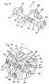
- FIG 1 two containers 1, 2 of conventional design are shown.
- the first container 1 shows that its larger side wall 3 has a large through opening 4, which here also with a cover plate 5 is closed.
- the through opening 4 is comparative wide and goes almost the entire height of the container 1.
- the container 2 has a corresponding Through opening on the side facing away from this view Page on.
- FIG. 2 shows that the passage opening 4 is open, because the cover plate 5 has been removed. Instead is to the frame profile surrounding the through opening 4 a rectangular bridging profile 6 as a sealing ring scheduled. It is above the level of the side wall 3 before. Its more detailed design results from the figures 5 to 9. are also on the upper corner fittings of the container 1 wedges 7, 8 attached, the closer form results from Figure 12. You stand over protect and protect the level of the bridging profile 6 this when container 2 approaches container 1.
- the second container 2 is - which is not visible here is - also on the side facing away from this view the cover plate there has been removed, however without inserting a bridging profile.
- the open one Through opening has the same position and size as the passage opening 4 in the first container 1.
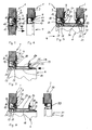
- FIGS of the two containers 1 and 2 The method for connecting is shown in FIGS of the two containers 1 and 2 by horizontal cross-sectional representations each closer to the same level shown.
- Figure 5 is a section of the side wall 3 of the container 1 with part of the through opening 4 to see.
- the side wall 3 is a sandwich construction with a foam core on the outside is occupied by metal plates.
- the through opening 4 is bordered by a frame profile 9, which is designed as an extruded hollow profile and is attached to the side wall 3.
- the frame profile 9 has an outward-facing edge sealing profile 10.
- an environmental sealing ring 11 is made from the edge sealing profile 10 embedded in an elastomer material. It also has one Keyway 12, which on the facing away from the environmental sealing ring 11 Side is limited by a wedge web 13.
- the cover plate 5 is also from the front Surround frame profile 14.
- the frame profile 14 has On the outside, an edge sealing profile 15, which is essentially complementary to the edge sealing profile 10 the side wall 3 is formed. 5 position shown the edge sealing profile 15 takes Wedge bar 13 and engages in the keyway 12.
- a sealing web 16 is provided which under Bias is applied to the environmental sealing ring 11.
- the border of the wedge web 13 has the edge sealing profile 15 resilient shielding strips 17, 18 on the wedge web 13 and for an electromagnetic Provide shielding.
- the EP-A-0 876 090 in which an essentially matching Sealing between the side wall and a door is described in detail.
- Figure 6 shows the side wall 3 after removal of the cover plate 5.
- Figure 7 shows the bridging profile 6 in on the frame profile 9 fixed position.
- the bridging profile 6 has a central hollow profile section 19 to which Connect overlap webs 20, 21 on the side.
- the in this view left overlap web 20 is on the inside of the frame profile 9 and there is a Variety of screws 22 releasably attached to this.
- a U-shaped groove 25 include, which serves as a gutter.
- the intervention profiles 23, 24 are mirror images and for taken almost identical to the edge sealing profile 15 on the frame profile 14 of the cover plate 5, d. H. complementary to the edge sealing profile 10 of the frame profile 9 on the side wall 3. Accordingly, the engagement profile 23 the wedge web 13 and engages in the Keyway 12 and is also on the environmental sealing ring 11th under tension.
- the engagement profiles 23, 24 have - Like the edge sealing profile 15 - shielding strips 26, 27, 28, 29. The seal between the engagement profile 23 and edge sealing profile 10 is thus equivalent like that between the edge sealing profiles 10 and 15 in the position according to FIG. 5.
- FIG. 8 shows the representation according to FIG. 7 by a corresponding cross-section through the Side wall 30 of the second container 2 added, and in the position shown in Figure 3.
- the cover plate has already been removed, so that the through opening 31 is free.
- the edge of the Through opening 31 is framed by a frame profile 32, the mirror image of the frame profile 9 on the Side wall 3 is formed so that its description referred to that of the frame profile 9 can be. Since the two containers 1, 2 are placed side by side are the through openings 4, 31 and thus also the frame profiles 9, 32 in alignment with each other.
- Figure 9 shows the situation after the contraction of the two containers 1, 2 by means of collets in the figure 4 apparent end position.
- this end position now also engage the right-hand engagement profile 24 and the edge sealing profile 33 of the frame profile 32 complementary into each other, in the same way as the engagement profile 23 in the edge sealing profile 10.
- Da both an environmental sealing ring 36 and the two shielding strips 28, 29 are present is the sealing effect equal to that between the round sealing profile 10 and engagement profile 23, d. H. to this extent there is symmetry.
- the overlap web 21 is not with the frame profile 32 connected. However, one is open Make the connection in the same way as between Overlap web 23 and frame profile 9.
- FIG. 10 shows a collet 37, as used for contraction the container 1, 2 used in the end position becomes. It comes in all four adjacent pairs of corner fittings used, each collet 37 a pair holds together by corner fittings in the end position.
- the collet 37 has a continuous spindle 38, which has two threaded portions 39, 40, which one are clockwise and once counterclockwise. On every thread section 39, 40 an engagement element is screwed on 41, 42, each with an engagement anchor 43, 44 are provided.
- the engagement anchor 43 44 are on the Standard openings in the corner fittings of such containers 1, 2 adjusted so that they fit into this form-fitting can.
- An actuating nut sits on the spindle 38 45, which is rotatably connected to the spindle 38.
- a Lock nut 46 is on the right-hand threaded section 40 screwed on.
- the spindle 38 passes through a guide plate 47, the one Has opening 48.
- a guide pin 49 In the opening 48 is a guide pin 49 with its longitudinal axis parallel to that of the Spindle 38 inserted, so that the guide pin 49 protrudes on both sides of the guide plate 47.
- the guide pin 49 has a cross section that corresponds to the Standard opening of the corner fittings of such containers 1, 2 in this way is adjusted that he just in these openings can border.
- the guide pin is on the right side 49 tapered.
- the attack elements 41, 42 are located in FIG the outer ends of the threaded portions 39, 40 and a distance equal to the distance of the openings in the corner fittings corresponds if the two containers 1, 2 so are placed next to each other, as can be seen from FIG. 3, d. H. if the second container on the wedges 7, 8 is present.
- the engagement anchors 43, 44 into the opening of a pair of two opposite Corner fittings can be used.
- Appropriate collets are also in the openings of the remaining pairs of opposite corner fittings used.
- the guide plate 47 is moved so that it on the respective Corner fitting of the first container 1 abuts and the left-hand part of the guide pin 49 into the opening this corner fitting.
- the end position can be seen from the section according to FIG. 11 see.
- the section shows a corner area of the container 1, 2 with standard corner fittings 50, 51, the top, Openings on the front and on the sides facing each other 52, 53, 54, 55.
- the guide plate 47 forms a stop between the two standard corner fittings 50, 51, the Guide bolt 49 in the openings not visible here the mutually facing surfaces of the standard fittings 50, 51 covered.
- the lock nut 46 is against the right-hand side Engagement element 42 tensioned so that the Spindle 38 cannot twist in one direction would increase the distance between the engagement elements 41, 42.
- the stop function of the guide plate 47 secures with the guide plates of the other collets that the Edge sealing profile. 33 with a defined preload on the engagement profile 24 of the bridging profile 6 for Plant comes, an overuse in this area however is avoided.
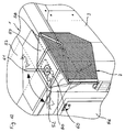
- Figure 12 shows the corner area of the container 1 with the Side wall 3, the end wall 56 and the top wall 57.
- side wall 3, end wall 56 and ceiling wall 57 collide in a corner, the outside is formed by the standard fitting 50.
- the deflecting wedge 7 is here on the standard fitting 50 (see Figure 2) attached. It has a base plate 58, which bears against the standard fitting 50. From this base plate 58 goes from a horizontal holding plate 59, the is grasped by a vertical axis 60. On the Axle 60 has an actuating lever 61 on the outside the axis 60 carries a not shown here Gag in the "up” position by the underlying opening 52 in the standard corner fitting 50 fits, in the "closed” position, however, the obvious ones Bordered edges of the opening 52. In the latter Position, the deflecting wedge 7 is fixed to the standard fitting. After turning the operating lever 61 in the The "open" position can be lifted off the standard fitting 50 and be removed. Then you can the collets 37 are attached and contracted.
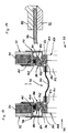
- Figures 13 and 14 correspond in principle to the representation according to Figure 9 with the exception that here is another Sealing ring 71 for connecting two juxtaposed Containers 72, 73 is used.
- the containers 72, 73 here are sections of each other facing side walls 74, 75 and those of them exposed through holes 76, 77 can be seen.
- the Through openings 76, 77 are of frame profiles 78, 79 edged, which are formed as extruded hollow profiles and attached to the associated side wall 74, 75 are.
- the frame profiles 78, 79 each point outwards pointing edge sealing profiles 80, 81, in each an environmental sealing ring 82, 83 made of an elastomer material is let in. They also have keyways 84, 85, on the respective environmental sealing ring 82, 83 facing away from a wedge web 86, 87 bounded become.
- the distance between the two side walls 74, 75 is bridged by the sealing ring 71.
- the sealing ring 71 has two edge rings 88, 89 which over a center ring 90 made of a reinforced elastomeric material are connected.
- the center ring 90 allows compensation of slight differences in position between the two Containers 72, 73.
- the edge rings 88, 89 have clamping rings 91, 92 on that with screws 93, 94 with the edge rings 88, 89 are connected.
- the edge rings 88, 89 have lateral overlap webs 96, 97 on the inside of the frame profiles 78 or 79 and with whom over a variety of Screws are detachably connected. Furthermore, the edge rings 88, 89 engagement profiles 98, 99, which are mirror images are trained and in themselves almost identical with the edge sealing profiles 80, 81 on the frame profiles 78, 79, so they are complementary to these. Corresponding grasp the engagement profiles 98, 99 the wedge webs 86, 87 and engage in the keyways 84, 85. With outer webs 100, 101, they are also due to the environmental sealing rings 82, 83 under tension.
- the engagement profiles 98, 99 each have a shielding strip 102, 103 on that for an electromagnetic Ensure sealing.
Landscapes
- Engineering & Computer Science (AREA)
- Architecture (AREA)
- Physics & Mathematics (AREA)
- Electromagnetism (AREA)
- Civil Engineering (AREA)
- Structural Engineering (AREA)
- Packages (AREA)
- Stackable Containers (AREA)
- Closures For Containers (AREA)
Applications Claiming Priority (2)
| Application Number | Priority Date | Filing Date | Title |
|---|---|---|---|
| DE19920613 | 1999-05-05 | ||
| DE19920613 | 1999-05-05 |
Publications (2)
| Publication Number | Publication Date |
|---|---|
| EP1050488A2 true EP1050488A2 (fr) | 2000-11-08 |
| EP1050488A3 EP1050488A3 (fr) | 2002-11-27 |
Family
ID=7907020
Family Applications (1)
| Application Number | Title | Priority Date | Filing Date |
|---|---|---|---|
| EP00105841A Withdrawn EP1050488A3 (fr) | 1999-05-05 | 2000-03-20 | Ensemble de conteneurs et procédé de solidarisation des conteneurs |
Country Status (2)
| Country | Link |
|---|---|
| EP (1) | EP1050488A3 (fr) |
| DE (1) | DE20005214U1 (fr) |
Families Citing this family (4)
| Publication number | Priority date | Publication date | Assignee | Title |
|---|---|---|---|---|
| DE102004002945A1 (de) * | 2004-01-21 | 2005-08-11 | Dennert Poraver Gmbh | Brandgeschützter Container, insbesondere begehbarer Gefahrgut-Container |
| DE102004031466B4 (de) * | 2004-06-30 | 2015-07-30 | Ulrich Malchow | Vorrichtung zur Aufnahme von Gütern |
| EP2357291A1 (fr) * | 2010-02-12 | 2011-08-17 | Hsu-Hua Huang | Architecture modulaire |
| DE102011053306A1 (de) * | 2011-09-06 | 2013-03-07 | Drehtainer Gmbh Spezial Container- Und Fahrzeugbau | Fahrzeug mit Auflieger in modularer Bauweise |
Citations (2)
| Publication number | Priority date | Publication date | Assignee | Title |
|---|---|---|---|---|
| EP0656742A1 (fr) | 1993-12-01 | 1995-06-07 | M. Schall GmbH + Co. KG | Dispositif de blindage contre les ondes et impulsions hautes fréquences |
| EP0876090A2 (fr) | 1997-03-14 | 1998-11-04 | M. Schall GmbH + Co. KG | Coffret avec les parois et au moins une ouverture dans les parois |
Family Cites Families (5)
| Publication number | Priority date | Publication date | Assignee | Title |
|---|---|---|---|---|
| GB1228200A (fr) * | 1968-11-14 | 1971-04-15 | ||
| US4492384A (en) * | 1983-04-25 | 1985-01-08 | General Motors Corporation | Sealing arrangement |
| US4599829A (en) * | 1983-08-25 | 1986-07-15 | Tandemloc, Inc. | Modular container building system |
| US5280984A (en) * | 1992-10-02 | 1994-01-25 | Paccar Inc. | Walk through boot assembly and method |
| US5735639A (en) * | 1996-12-13 | 1998-04-07 | The United States Of America As Represented By The Secretary Of The Navy | Modular mobile safety structure for containment and handling of hazardous materials |
-
2000
- 2000-03-18 DE DE20005214U patent/DE20005214U1/de not_active Expired - Lifetime
- 2000-03-20 EP EP00105841A patent/EP1050488A3/fr not_active Withdrawn
Patent Citations (2)
| Publication number | Priority date | Publication date | Assignee | Title |
|---|---|---|---|---|
| EP0656742A1 (fr) | 1993-12-01 | 1995-06-07 | M. Schall GmbH + Co. KG | Dispositif de blindage contre les ondes et impulsions hautes fréquences |
| EP0876090A2 (fr) | 1997-03-14 | 1998-11-04 | M. Schall GmbH + Co. KG | Coffret avec les parois et au moins une ouverture dans les parois |
Also Published As
| Publication number | Publication date |
|---|---|
| DE20005214U1 (de) | 2000-08-17 |
| EP1050488A3 (fr) | 2002-11-27 |
Similar Documents
| Publication | Publication Date | Title |
|---|---|---|
| DE69412563T2 (de) | Schrank mit Eckverbindung und ein Schaltschrank mit solchen Verbindungen | |
| DE69104687T2 (de) | Metallrahmen für einen schrank. | |
| EP0853832B1 (fr) | Cadre pour armoire de distribution | |
| EP0751595B1 (fr) | Bâti pour une armoire de commutation | |
| DE3229814A1 (de) | Anordnung zum verbinden flaechenfoermiger elemente an benachbarten laengskanten | |
| DE2851549B1 (de) | Vorrichtung zum Verbinden von Schaltafeln insbesondere im Bereich von Abstufungen eines Bauwerkes | |
| EP0342478A2 (fr) | Socle pour une armoire de commutations ou similaires | |
| DE8030908U1 (de) | Vorrichtung zum verbinden von platten und/oder staeben | |
| EP1050488A2 (fr) | Ensemble de conteneurs et procédé de solidarisation des conteneurs | |
| DE3422222C2 (de) | Gestell aus einem Profilstab und daran mit einem Verbinder angebrachter Platte o. dgl. Gestellteil | |
| WO1999012657A1 (fr) | Paroi de cabine pour chaine de vernissage | |
| EP0269126B1 (fr) | Boîtier blindé | |
| DE2516264C2 (de) | Befestigungsvorrichtung für ein Beschlagteil an Profilstäben aus Metall oder Kunststoff | |
| DE1690003C3 (de) | Zerlegbarer Kasten zur Unterbringung elektrischer Geräte | |
| DE3230287A1 (de) | Roentgen-filmkassette | |
| EP1495996B1 (fr) | Convoyeur à charnieres avec dispositif de guidage | |
| EP0876090B1 (fr) | Coffret avec les parois et au moins une ouverture dans les parois | |
| DE2546087C2 (de) | Kastenelemente für eine isolierstoff-gekapselte Schaltanlage mit Schalt-, Steuer- und Regeleinrichtung | |
| EP0562500B1 (fr) | Entrée de serrure cylindrique | |
| DE2302538C3 (de) | Stulpschienen-Eckverbindung, insbesondere von Treibstangenbeschlägen | |
| EP0465905A1 (fr) | Revêtement de plafond | |
| DE1962781C2 (de) | Treibstangenverschluß, insbesondere im Falz des Flügels eines Fensters, einer Tür od.dgl. anzuordnendes Kantengetriebe | |
| EP0656742B1 (fr) | Dispositif de blindage contre les ondes et impulsions hautes fréquences | |
| EP0539891A2 (fr) | Porte pivotante pour conteneur | |
| DE69810674T2 (de) | Verbesserte Kabelrinne |
Legal Events
| Date | Code | Title | Description |
|---|---|---|---|
| PUAI | Public reference made under article 153(3) epc to a published international application that has entered the european phase |
Free format text: ORIGINAL CODE: 0009012 |
|
| AK | Designated contracting states |
Kind code of ref document: A2 Designated state(s): AT BE CH CY DE DK ES FI FR GB GR IE IT LI LU MC NL PT SE |
|
| AX | Request for extension of the european patent |
Free format text: AL;LT;LV;MK;RO;SI |
|
| RIC1 | Information provided on ipc code assigned before grant |
Free format text: 7B 65D 90/00 A, 7E 04B 1/348 B, 7B 65D 88/02 B |
|
| PUAL | Search report despatched |
Free format text: ORIGINAL CODE: 0009013 |
|
| AK | Designated contracting states |
Kind code of ref document: A3 Designated state(s): AT BE CH CY DE DK ES FI FR GB GR IE IT LI LU MC NL PT SE |
|
| AX | Request for extension of the european patent |
Free format text: AL;LT;LV;MK;RO;SI |
|
| AKX | Designation fees paid | ||
| REG | Reference to a national code |
Ref country code: DE Ref legal event code: 8566 |
|
| STAA | Information on the status of an ep patent application or granted ep patent |
Free format text: STATUS: THE APPLICATION IS DEEMED TO BE WITHDRAWN |
|
| 18D | Application deemed to be withdrawn |
Effective date: 20030527 |