EP1050431B1 - Ausrichtvorrichtung zum Einpassen eines Kraftfahrzeugscheinwerfers in einen Karosserieausschnitt - Google Patents
Ausrichtvorrichtung zum Einpassen eines Kraftfahrzeugscheinwerfers in einen Karosserieausschnitt Download PDFInfo
- Publication number
- EP1050431B1 EP1050431B1 EP00109316A EP00109316A EP1050431B1 EP 1050431 B1 EP1050431 B1 EP 1050431B1 EP 00109316 A EP00109316 A EP 00109316A EP 00109316 A EP00109316 A EP 00109316A EP 1050431 B1 EP1050431 B1 EP 1050431B1
- Authority
- EP
- European Patent Office
- Prior art keywords
- alignment mechanism
- bodywork
- motor vehicle
- adjusting element
- outer skin
- Prior art date
- Legal status (The legal status is an assumption and is not a legal conclusion. Google has not performed a legal analysis and makes no representation as to the accuracy of the status listed.)
- Expired - Lifetime
Links
- 239000002184 metal Substances 0.000 claims description 4
- 238000003780 insertion Methods 0.000 description 1
- 230000037431 insertion Effects 0.000 description 1
- 238000004519 manufacturing process Methods 0.000 description 1
- 238000000034 method Methods 0.000 description 1
- 238000004513 sizing Methods 0.000 description 1
Images

Classifications
-
- B—PERFORMING OPERATIONS; TRANSPORTING
- B60—VEHICLES IN GENERAL
- B60Q—ARRANGEMENT OF SIGNALLING OR LIGHTING DEVICES, THE MOUNTING OR SUPPORTING THEREOF OR CIRCUITS THEREFOR, FOR VEHICLES IN GENERAL
- B60Q1/00—Arrangement of optical signalling or lighting devices, the mounting or supporting thereof or circuits therefor
- B60Q1/02—Arrangement of optical signalling or lighting devices, the mounting or supporting thereof or circuits therefor the devices being primarily intended to illuminate the way ahead or to illuminate other areas of way or environments
- B60Q1/04—Arrangement of optical signalling or lighting devices, the mounting or supporting thereof or circuits therefor the devices being primarily intended to illuminate the way ahead or to illuminate other areas of way or environments the devices being headlights
- B60Q1/0408—Arrangement of optical signalling or lighting devices, the mounting or supporting thereof or circuits therefor the devices being primarily intended to illuminate the way ahead or to illuminate other areas of way or environments the devices being headlights built into the vehicle body, e.g. details concerning the mounting of the headlamps on the vehicle body
- B60Q1/0433—Arrangement of optical signalling or lighting devices, the mounting or supporting thereof or circuits therefor the devices being primarily intended to illuminate the way ahead or to illuminate other areas of way or environments the devices being headlights built into the vehicle body, e.g. details concerning the mounting of the headlamps on the vehicle body the housing being fastened onto the vehicle body using screws
-
- B—PERFORMING OPERATIONS; TRANSPORTING
- B60—VEHICLES IN GENERAL
- B60Q—ARRANGEMENT OF SIGNALLING OR LIGHTING DEVICES, THE MOUNTING OR SUPPORTING THEREOF OR CIRCUITS THEREFOR, FOR VEHICLES IN GENERAL
- B60Q1/00—Arrangement of optical signalling or lighting devices, the mounting or supporting thereof or circuits therefor
- B60Q1/02—Arrangement of optical signalling or lighting devices, the mounting or supporting thereof or circuits therefor the devices being primarily intended to illuminate the way ahead or to illuminate other areas of way or environments
- B60Q1/04—Arrangement of optical signalling or lighting devices, the mounting or supporting thereof or circuits therefor the devices being primarily intended to illuminate the way ahead or to illuminate other areas of way or environments the devices being headlights
- B60Q1/0408—Arrangement of optical signalling or lighting devices, the mounting or supporting thereof or circuits therefor the devices being primarily intended to illuminate the way ahead or to illuminate other areas of way or environments the devices being headlights built into the vehicle body, e.g. details concerning the mounting of the headlamps on the vehicle body
- B60Q1/045—Arrangement of optical signalling or lighting devices, the mounting or supporting thereof or circuits therefor the devices being primarily intended to illuminate the way ahead or to illuminate other areas of way or environments the devices being headlights built into the vehicle body, e.g. details concerning the mounting of the headlamps on the vehicle body with provision for adjusting the alignment of the headlamp housing with respect to the vehicle body
Definitions
- the invention relates to an alignment device for fitting a motor vehicle headlight in a body cutout, which is formed by body shell parts which are attached to a Body supports are attached.
- the body cutout for receiving the headlight usually from a fender, a bumper and a hood formed.
- a circumferential Gap Between the diffuser of the fitted front headlight and the said body outer skin parts usually remains a circumferential Gap, due to its exposed location from the outside is clearly visible. Passing inaccuracies in this area fall especially because it leads to a visually easily detectable unevenness lead the gap width. They are therefore alignment devices been developed, with the help of the motor vehicle headlights in the body cut-out so manually let align that the circumferential gap a substantially has uniform width.
- the positioning of the motor vehicle headlight in the body cutout usually takes place so that the motor vehicle headlights with the help of suitable adjusting elements opposite Align the body shell parts.
- suitable adjusting elements opposite Align the body shell parts.
- DE-C1-43 40 306 for example, such a generic adjustment known.
- the adjustment here provides an adjustable connection between the housing of the motor vehicle headlight and a Sheet metal section rigidly with the body shell parts connected is. With the help of the adjustment can be on this Way the vehicle headlamps relative to the body shell parts align.
- the difficulty with alignment devices This type is that the motor vehicle headlights in all three spatial directions simultaneously must be positioned and then attached. A single one Person is often overwhelmed with this task, because at the same time held the motor vehicle headlight, possibly moved and must be observed from the front. Corresponding high are the costs that the alignment at the Motor vehicle final assembly caused.
- an alignment device which Retaining tabs attached to the housing of the motor vehicle headlight includes. At the body shell parts are stops provided, to which the tabs on insertion of the motor vehicle headlight in the body cut to strike. In this Position the tabs with the body shell parts screwed. In this process, the fitting inaccuracies compensated by the body outer skin parts slightly bent in the direction of the housing of the motor vehicle headlight be, because the latter is largely undeformable.
- the alignment with this known alignment device is very simple and be carried out quickly.
- the invention achieves this object by providing an alignment device with the features of claim 1.
- the alignment device comprises first means for rigidly attaching the Motor vehicle headlight on a body support and second Means for aligning the body parts with respect to the body support. It is thus based on a different principle of orientation, because in contrast to known alignment devices the motor vehicle headlamp will not face the exterior of the body, but they are more likely to be compared aligned with the vehicle headlight. As the motor vehicle headlights rigidly connected to the body support, its position remains with a slight damage to the body shell parts unchanged. In addition, there are considerable manufacturing advantages, since now no longer the vehicle headlights aligned in three spatial directions simultaneously needs to be. Instead, the body shell parts can gradually over the vehicle headlight be aligned.
- the second Mean a body-fixed leadership body and a on it screwed hollow cylindrical adjusting body.
- the adjusting body are associated with guide means, the one from a twisting resulting from the adjusting body on the guide body Axialmony the adjusting body on the at least one body shell part transfer.
- This structurally simple design The alignment device allows to go through alone Turn the adjusting body to make the alignment. On Loosening of fasteners is not required for this purpose.
- the guide means according to claim 3 comprise a on the circumference of the adjusting body circumferential groove and a projection, which engages in the groove and rigid with the at least a body shell part is connected.
- Sizing of the groove can also be larger in this way Transfer adjusting forces.
- the adjusting body provided with radially outwardly facing webs, the adjustment facilitate the adjustment.
- This embodiment is especially advantageous if the alignment device to a hard to reach place in the front area of the motor vehicle is arranged.
- the webs serve as a stop for an elongated Subject, about a screwdriver.
- To the adjusting body twisting on the guide body, the object is in pressed approximately tangential direction against the webs. Thus needs the alignment only over a narrow gap to be reached from the outside.
- the first means one with the housing of the motor vehicle headlight rigidly connected socket and a screwed therein Screw. Between the head of the screw and the facing Front side of the socket is the guide body and a body-fixed Part clamped.
- the motor vehicle headlight and the Guide body are thus together with only one screw attached to the body support.
- the guide body constructed according to claim 6 in two parts and comprises an inner part from a metal, which by the bracing through the screw receives emerging forces, and an outer part a plastic, on which the adjustment body is seated.
- Fig. 1 shows a simplified representation of a section from a motor vehicle front.
- the body shell parts are in detail around a mudguard 3a, a bumper 3b and a bonnet 3c. Between the body shell parts and the Lens 21 of the motor vehicle headlamp remains a circumferential Gap 23, due to its exposed location from the outside is clearly visible.
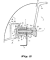
- Fig. 2 shows a motor vehicle headlight 2, of which only each a part of the lens 21 and the headlight housing 22 are shown.
- To the left of the lens 21 is one the body shell parts 3 shown in Fig. 1 can be seen.
- the gap 23 between the lens 21 and the body shell part 3 should be adjustable by means of the alignment device his.
- Dark highlighted in Fig. 2 is a tab 4, the rigidly connected to a body carrier or an integral one Part of it is so that the tab 4 a body-fixed Represents reference point.
- the body carrier it can For example, the front stem cross member of a Motor vehicle body shell act.
- the headlight housing 22 has laterally a bore 221, in the a socket 5 is firmly inserted.
- the socket 5 is itself as well provided with a bore coaxial with the bore 221 runs and has an internal thread 51.
- the Bush made of metal and the Schweinwerfergeophuse 22 from a Hard plastic.
- the bolt end in a in the headlight housing 22nd provided blind hole 222 extends.
- a sleeve-shaped guide body 7 and the tab 4 clamped which has a bore 41 for the passage of the bolt.
- the guide body 7 is constructed in two parts.
- On Metallic inner part 72 takes the by tightening the Screw 6 resulting forces, while the outer part 71 of a hard plastic and outside with a thread 711 is provided. After screwing thus form the tab 4, the guide body 7, the socket 5 and thus the motor vehicle headlight 2 a rigidly connected to the body support Unit.
- a hollow cylindrical Adjusting body 8 screwed, along its circumference a Guide groove 81 and preferably also made of a hard plastic consists. In this groove engage projections 31, the via connecting parts 32 rigidly with the body shell part 3 are connected. Now, the adjusting body 8 by rotation the tightened guide body 7, for example in the direction shifted the socket 5, the interventions 31 perform this axial movement with and thus adjust the body shell part 3 also in this direction. As a result, reduced the width of the gap 23.
- Fig. 3 shows a section A-A through the alignment device according to Fig. 1.
- the connecting parts 32 form a kind of housing, which is the head of the Verstell stressess partially encloses.
- the adjusting element 8 engages, as shown in Fig. 3, with a elongated object 90 in an opening of the housing and pushes against one of the webs 82. This causes the rotation of the Adjustment body and thus the adjustment of the body shell part 3 opposite the body-mounted motor vehicle headlight Second
Landscapes
- Engineering & Computer Science (AREA)
- Mechanical Engineering (AREA)
- Lighting Device Outwards From Vehicle And Optical Signal (AREA)
Description
- Fig. 1
- eine vereinfachte Darstellung eines Kraftfahrzeugscheinwerfers in einem Karosserieausschnitt,
- Fig. 2
- eine erfindungsgemäße Ausrichtvorrichtung in einem Längsschnitt, und
- Fig. 3
- einen Schnitt durch eine Ausrichtvorrichtung nach Fig. 1 entlang der Schnittlinie A.
Claims (7)
- Ausrichtvorrichtung zum Einpassen eines Kraftfahrzeugscheinwerfers (2) in einen Karosserieausschnitt, der von an einem Karosserieträger (4) befestigten Karosserieaußenhautteilen (3; 3a, 3b, 3c) gebildet wird,
dadurch gekennzeichnet, daßdie Ausrichtvorrichtung erste Mittel (5, 6) zum starren Befestigen des Kraftfahrzeugscheinwerfers an dem Karosserieträger undzweite Mittel (7, 8) zum Ausrichten wenigstens eines Karosserieaußenhautteils (3) gegenüber dem Karosserieträger umfaßt. - Ausrichtvorrichtung nach Anspruch 1,
dadurch gekennzeichnet, daß
die zweiten Mittel einen karosseriefesten Führungskörper (7) und einen darauf aufgeschraubten hohlzylindrischen Verstellkörper (8) umfassen, wobei dem Verstellkörper Führungsmittel (81, 31) zugeordnet sind, die eine aus einem Verdrehen des Verstellkörpers auf dem Führungskörper resultierende Axialbewegung des Verstellkörpers auf das wenigstens eine Karosserieaußenhautteil (3) übertragen. - Ausrichtvorrichtung nach Anspruch 2,
dadurch gekennzeichnet, daß
die Führungsmittel eine auf dem Umfang des Verstellkörpers umlaufende Nut (81) und einen Vorsprung (31) umfassen, der in die Nut eingreift und starr mit dem wenigstens einen Karosserieaußenhautteil verbunden ist. - Ausrichtvorrichtung nach einem der Ansprüche 2 oder 3,
dadurch gekennzeichnet, daß
der Verstellkörper auf seinem Umfang mit radial nach außen weisenden Stegen (82) versehen ist. - Ausrichtvorrichtung nach einem der Ansprüche 2 bis 4,
dadurch gekennzeichnet, daß
die ersten Mittel eine mit dem Gehäuse (22) des Kraftfahrzeugscheinwerfers (2) starr verbundene Buchse (5) und eine darin eingeschraubte Schraube (6) umfassen, wobei zwischen dem Kopf (61) der Schraube und der zugewandten Stirnseite der Buchse der Führungskörper (7) und ein karosseriefestes Teil (4) eingespannt ist. - Ausrichtvorrichtung nach Anspruch 5,
dadurch gekennzeichnet, daß
der Führungskörper (7) ein aus einem Metall bestehendes Innenteil (72) und ein aus einem Kunststoff bestehendes Außenteil (71) umfaßt. - Kraftfahrzeug mit mindestens einen Scheinwerfer,
dadurch gekennzeichnet, daß
zwei Karosserieaußenhautteile (3a, 3b) im Bereich des Kraftfahrzeugscheinwerfers (2) so miteinander verbunden sind, daß sie gemeinsam mit genau einer Ausrichtvorrichtung nach einem der vorhergehenden Ansprüche ausrichtbar sind.
Applications Claiming Priority (2)
| Application Number | Priority Date | Filing Date | Title |
|---|---|---|---|
| DE19920521 | 1999-05-05 | ||
| DE19920521A DE19920521C2 (de) | 1999-05-05 | 1999-05-05 | Ausrichtvorrichtung zum Einpassen eines Kraftfahrzeugschweinwerfers in einen Karosserieausschnitt |
Publications (3)
| Publication Number | Publication Date |
|---|---|
| EP1050431A2 EP1050431A2 (de) | 2000-11-08 |
| EP1050431A3 EP1050431A3 (de) | 2003-05-14 |
| EP1050431B1 true EP1050431B1 (de) | 2004-03-24 |
Family
ID=7906950
Family Applications (1)
| Application Number | Title | Priority Date | Filing Date |
|---|---|---|---|
| EP00109316A Expired - Lifetime EP1050431B1 (de) | 1999-05-05 | 2000-04-29 | Ausrichtvorrichtung zum Einpassen eines Kraftfahrzeugscheinwerfers in einen Karosserieausschnitt |
Country Status (3)
| Country | Link |
|---|---|
| EP (1) | EP1050431B1 (de) |
| DE (2) | DE19920521C2 (de) |
| ES (1) | ES2216754T3 (de) |
Families Citing this family (4)
| Publication number | Priority date | Publication date | Assignee | Title |
|---|---|---|---|---|
| FR2866857B1 (fr) * | 2004-02-26 | 2006-05-26 | Renault Sas | Aile de carrosserie de vehicule automobile en matiere plastique pourvue d'un dispositif d'indexage |
| ES2282003B1 (es) * | 2005-03-29 | 2008-08-16 | Automotive Lighting Rear Lamps España, S.A. | Dispositivo de soporte para faros de automoviles. |
| EP3275733B1 (de) * | 2016-07-29 | 2019-10-09 | Ford Global Technologies, LLC | Scheinwerferbefestigungssystem für kraftfahrzeuge und verfahren |
| DE102021000240A1 (de) | 2021-01-19 | 2022-07-21 | Mercedes-Benz Group AG | Halter für ein Anbauteil, insbesondere für eine Leuchteinheit eines Kraftwagens |
Family Cites Families (4)
| Publication number | Priority date | Publication date | Assignee | Title |
|---|---|---|---|---|
| DE3629124C1 (en) * | 1986-08-27 | 1987-11-26 | Daimler Benz Ag | Device for the edge-equidistant and surface-flush setting and attachment of a headlamp housing in a vehicle-body section of the same shape |
| DE3718841A1 (de) * | 1987-06-05 | 1988-12-22 | Audi Ag | Rahmenanordnung fuer kraftfahrzeuge |
| DE4020364C2 (de) * | 1990-06-27 | 1993-11-04 | Opel Adam Ag | Frontscheinwerfer |
| DE4340306C1 (de) * | 1993-11-26 | 1994-11-17 | Daimler Benz Ag | Ausrichtvorrichtung zur Einpassung eines Kraftfahrzeugscheinwerfers in einen Karosserieausschnitt |
-
1999
- 1999-05-05 DE DE19920521A patent/DE19920521C2/de not_active Expired - Fee Related
-
2000
- 2000-04-29 ES ES00109316T patent/ES2216754T3/es not_active Expired - Lifetime
- 2000-04-29 DE DE50005762T patent/DE50005762D1/de not_active Expired - Fee Related
- 2000-04-29 EP EP00109316A patent/EP1050431B1/de not_active Expired - Lifetime
Also Published As
| Publication number | Publication date |
|---|---|
| DE50005762D1 (de) | 2004-05-13 |
| EP1050431A3 (de) | 2003-05-14 |
| DE19920521C2 (de) | 2001-07-26 |
| ES2216754T3 (es) | 2004-11-01 |
| DE19920521A1 (de) | 2000-11-16 |
| EP1050431A2 (de) | 2000-11-08 |
Similar Documents
| Publication | Publication Date | Title |
|---|---|---|
| DE69624299T2 (de) | Kurbelarmanordnung für ein Fahrrad und Montagewerkzeug | |
| EP1979634B1 (de) | Montageeinheit für die befestigungsöse eines gurtschlosses | |
| EP0694465B1 (de) | Kraftfahrzeugkarosserie mit integriertem Strukturquerträger | |
| EP1764516A2 (de) | Schraubverbindung mit Toleranzausgleich | |
| DE69702478T2 (de) | Leuchtenbefestigung mit akkordeonförmig gefalteter Feder an der Karosserie eines Fahrzeuges | |
| DE19616234A1 (de) | Vorrichtung für die Befestigung einer Nabe auf einer Welle, insbesondere einer Lenkradnabe auf einer Lenksäule | |
| DE102017128890A1 (de) | Montagemodul für eine Fahrzeugleuchte | |
| DE10130411C2 (de) | Scheibenwischerträgereinheit | |
| DE102012110652B4 (de) | Vorrichtung zur Fugeneinstellung zwischen Anbauteilen | |
| EP3110666B1 (de) | Befestigungsanordnung einer kühlerverkleidung und eines stossfängers an einem frontendträger eines kraftwagens | |
| EP3755548B1 (de) | Speichenrad für schlauchlose reifen | |
| DE19920521C2 (de) | Ausrichtvorrichtung zum Einpassen eines Kraftfahrzeugschweinwerfers in einen Karosserieausschnitt | |
| DE102020104316B3 (de) | Vorrichtung zum Befestigen eines Leuchtenbandes an einem Kraftfahrzeug | |
| DE202017105765U1 (de) | Befestigungsvorrichtung zur Befestigung von mindestens einem Bauteil | |
| EP1595770B1 (de) | Kraftfahrzeug mit einer Leuchtmittelaufnahme für ein Aussenleuchtmittel | |
| EP1612432B1 (de) | Befestigungsanordnung für eine Verkleidung und Befestigungsverfahren | |
| EP0743226A2 (de) | Leuchtengehäuse | |
| DE102021116803A1 (de) | Halter, Baukasten und Verfahren zum Montieren eines Halters | |
| EP3456586B1 (de) | Vorrichtung und verfahren zur positionsgenauen, wenigstens teilweisen befestigung von fahrzeugleuchten an fahrzeugen, insbesondere kraftfahrzeugen, sowie fahrzeugleuchte | |
| DE102023003983B4 (de) | Fahrzeug, Außenhautbauteil und Außenhautsystem | |
| DE3421051C2 (de) | ||
| DE19743928A1 (de) | Anordnung zur verdeckten Verbindung von zwei Bauteilen, insbesondere zur Befestigung einer Türinnenverkleidung einer Kraftfahrzeugtür | |
| DE1775764A1 (de) | Schraub- od.dgl.Verbindung fuer Blechteile,insbesondere fuer die schalenfoermigen Gehaeuschaelften eines Radgelenkes von Kraftfahrzeugen | |
| DE4340306C1 (de) | Ausrichtvorrichtung zur Einpassung eines Kraftfahrzeugscheinwerfers in einen Karosserieausschnitt | |
| DE4322353C2 (de) | Vorrichtung zum flächigen Befestigen eines Stoßfängerträgers an einer Kraftfahrzeugkarosserie |
Legal Events
| Date | Code | Title | Description |
|---|---|---|---|
| PUAI | Public reference made under article 153(3) epc to a published international application that has entered the european phase |
Free format text: ORIGINAL CODE: 0009012 |
|
| AK | Designated contracting states |
Kind code of ref document: A2 Designated state(s): AT BE CH CY DE DK ES FI FR GB GR IE IT LI LU MC NL PT SE |
|
| AX | Request for extension of the european patent |
Free format text: AL;LT;LV;MK;RO;SI |
|
| PUAL | Search report despatched |
Free format text: ORIGINAL CODE: 0009013 |
|
| AK | Designated contracting states |
Designated state(s): AT BE CH CY DE DK ES FI FR GB GR IE IT LI LU MC NL PT SE |
|
| AX | Request for extension of the european patent |
Extension state: AL LT LV MK RO SI |
|
| 17P | Request for examination filed |
Effective date: 20030408 |
|
| GRAP | Despatch of communication of intention to grant a patent |
Free format text: ORIGINAL CODE: EPIDOSNIGR1 |
|
| GRAS | Grant fee paid |
Free format text: ORIGINAL CODE: EPIDOSNIGR3 |
|
| AKX | Designation fees paid |
Designated state(s): DE ES FR GB IT |
|
| GRAA | (expected) grant |
Free format text: ORIGINAL CODE: 0009210 |
|
| AK | Designated contracting states |
Kind code of ref document: B1 Designated state(s): DE ES FR GB IT |
|
| REG | Reference to a national code |
Ref country code: GB Ref legal event code: FG4D Free format text: NOT ENGLISH |
|
| REG | Reference to a national code |
Ref country code: IE Ref legal event code: FG4D Free format text: GERMAN |
|
| REF | Corresponds to: |
Ref document number: 50005762 Country of ref document: DE Date of ref document: 20040513 Kind code of ref document: P |
|
| GBT | Gb: translation of ep patent filed (gb section 77(6)(a)/1977) |
Effective date: 20040603 |
|
| REG | Reference to a national code |
Ref country code: IE Ref legal event code: FD4D |
|
| REG | Reference to a national code |
Ref country code: ES Ref legal event code: FG2A Ref document number: 2216754 Country of ref document: ES Kind code of ref document: T3 |
|
| ET | Fr: translation filed | ||
| PLBE | No opposition filed within time limit |
Free format text: ORIGINAL CODE: 0009261 |
|
| STAA | Information on the status of an ep patent application or granted ep patent |
Free format text: STATUS: NO OPPOSITION FILED WITHIN TIME LIMIT |
|
| 26N | No opposition filed |
Effective date: 20041228 |
|
| PGFP | Annual fee paid to national office [announced via postgrant information from national office to epo] |
Ref country code: FR Payment date: 20050412 Year of fee payment: 6 |
|
| PGFP | Annual fee paid to national office [announced via postgrant information from national office to epo] |
Ref country code: ES Payment date: 20050418 Year of fee payment: 6 Ref country code: GB Payment date: 20050418 Year of fee payment: 6 |
|
| PG25 | Lapsed in a contracting state [announced via postgrant information from national office to epo] |
Ref country code: GB Free format text: LAPSE BECAUSE OF NON-PAYMENT OF DUE FEES Effective date: 20060429 |
|
| PGFP | Annual fee paid to national office [announced via postgrant information from national office to epo] |
Ref country code: IT Payment date: 20060430 Year of fee payment: 7 |
|
| PG25 | Lapsed in a contracting state [announced via postgrant information from national office to epo] |
Ref country code: ES Free format text: LAPSE BECAUSE OF NON-PAYMENT OF DUE FEES Effective date: 20060503 |
|
| GBPC | Gb: european patent ceased through non-payment of renewal fee |
Effective date: 20060429 |
|
| REG | Reference to a national code |
Ref country code: FR Ref legal event code: ST Effective date: 20061230 |
|
| REG | Reference to a national code |
Ref country code: ES Ref legal event code: FD2A Effective date: 20060503 |
|
| PG25 | Lapsed in a contracting state [announced via postgrant information from national office to epo] |
Ref country code: FR Free format text: LAPSE BECAUSE OF NON-PAYMENT OF DUE FEES Effective date: 20060502 |
|
| PGFP | Annual fee paid to national office [announced via postgrant information from national office to epo] |
Ref country code: DE Payment date: 20090422 Year of fee payment: 10 |
|
| PG25 | Lapsed in a contracting state [announced via postgrant information from national office to epo] |
Ref country code: IT Free format text: LAPSE BECAUSE OF NON-PAYMENT OF DUE FEES Effective date: 20070429 |
|
| PG25 | Lapsed in a contracting state [announced via postgrant information from national office to epo] |
Ref country code: DE Free format text: LAPSE BECAUSE OF NON-PAYMENT OF DUE FEES Effective date: 20101103 |