EP1050087B1 - Elektrischer stecker mit einem betätigungsschieber - Google Patents
Elektrischer stecker mit einem betätigungsschieber Download PDFInfo
- Publication number
- EP1050087B1 EP1050087B1 EP99900105A EP99900105A EP1050087B1 EP 1050087 B1 EP1050087 B1 EP 1050087B1 EP 99900105 A EP99900105 A EP 99900105A EP 99900105 A EP99900105 A EP 99900105A EP 1050087 B1 EP1050087 B1 EP 1050087B1
- Authority
- EP
- European Patent Office
- Prior art keywords
- actuating slide
- connector
- connectors
- guide
- actuating
- Prior art date
- Legal status (The legal status is an assumption and is not a legal conclusion. Google has not performed a legal analysis and makes no representation as to the accuracy of the status listed.)
- Expired - Lifetime
Links
Images
Classifications
-
- H—ELECTRICITY
- H01—ELECTRIC ELEMENTS
- H01R—ELECTRICALLY-CONDUCTIVE CONNECTIONS; STRUCTURAL ASSOCIATIONS OF A PLURALITY OF MUTUALLY-INSULATED ELECTRICAL CONNECTING ELEMENTS; COUPLING DEVICES; CURRENT COLLECTORS
- H01R13/00—Details of coupling devices of the kinds covered by groups H01R12/70 or H01R24/00 - H01R33/00
- H01R13/62—Means for facilitating engagement or disengagement of coupling parts or for holding them in engagement
- H01R13/629—Additional means for facilitating engagement or disengagement of coupling parts, e.g. aligning or guiding means, levers, gas pressure electrical locking indicators, manufacturing tolerances
- H01R13/62905—Additional means for facilitating engagement or disengagement of coupling parts, e.g. aligning or guiding means, levers, gas pressure electrical locking indicators, manufacturing tolerances comprising a camming member
Definitions
- the invention relates to connectors with an actuating slide having camming slots for receiving a guide pin of a complementary connector for the purpose of mating the connectors, and in particular to assuring the actuating slide is properly positioned at the time of mating.
- auxiliary mechanical structure may be an actuating slides or levers. Actuating slides are normally moved in a direction transverse to the plug-in direction of the mating connectors. The actuating slide is normally integrated into one of the connectors and has either a camming groove or a guide pin, the mating connector then includes the other part. When the two connectors are joined together, the actuation of the actuating slide causes the guide pin to move through the camming groove.
- EP 587 174 A2 discloses an electrical connector arrangement, in particular for door connectors in automobiles.
- the connector arrangement has an insulating housing and an actuating slide of conventional U-shaped design.
- the connector housings are brought into the mated position by actuation of the actuating slide.
- the actuating slide has two camming grooves on each side wall of the U-shape.
- the guide pins, which are arranged on the connector housing move in these camming grooves.
- the actuating slide In order to mate the two complementary connectors, the actuating slide must be in a first position, the entry position, so that the guide pins enter the camming grooves.
- the actuating slide is then moved to a second position, the end position, where the two connectors are interconnected. Since the actuating slide could easily move out of the entry position, it is usually necessary that the actuating slide initially be repositioned prior to the connectors being joined together. This requires an additional work step, which has a disadvantageous effect particularly in the case of conveyor-line assembly.
- EP 501 502 A2 discloses a connector arrangement having a first and a second complementary connector, in which a rotatable plate, on which camming grooves are provided, is provided instead of an actuating slide.
- the connector housing of the first complementary connector, to which the rotatable plate is fastened in a rotatable manner also has a guide slot
- the housing of the second complementary connector has a guide pin which is guided correspondingly during rotation of the rotatable plate through the guide slot and into the camming groove, whereby upon actuation of the lever, the two connectors are joined together.
- the rotatable plate As the rotatable plate also moves through a guide slot in the housing, on which it is rotatably mounted, from a starting position to an end position, it is particularly important for the rotatable plate to be in the starting position when the two connectors are intended to be interconnected. Since it cannot easily be discerned from outside whether the guide grooves are in the correct position, it would be helpful to interlock the guide plate and the connector housing in the entry position. This interlocking would be released only when the complementary connector is inserted.
- JP 62 15 827 A discloses a further connector arrangement incorporating an actuating slide.
- a latch is provided for locking the actuating slide in an entry position where the guide pin can be introduced into the guide groove through the guide slot.
- the latch is designed in the form of latching arms with latching lugs on the actuating slide which are resilient perpendicularly to the plug-in direction. The latching is effected with a corresponding depression in the housing of the connector, which housing accommodates the actuating slide.
- Means for unlocking the latches are provided on the complementary connector, in such a way that when the connectors are joined together, the latches are unlocked and the actuating slide can be moved. Consequently, the actuating slide can only be moved from the entry position when the locking is released by inserting a complementary connector.
- WO97/07567 likewise discloses a connector arrangement with an actuating slide.
- an arm is provided on the housing.
- the arm is resilient in the plug-in direction and engages in a groove in the actuating slide.
- a wedge which interacts with the means for unlocking the actuating slide in the entry position so that the actuating slide can be moved.
- the object of the invention is to specify an electrical connector arrangement with an actuating slide in which inadvertent pushing of the actuating slide from the entry position into the end latching position is prevented in a simple manner.
- the locking members are opened in a single work operation, that is during the insertion of the second complementary connector when the two connectors are being joined together at the same time.
- the locking members are designed as an arm on the actuating slide with a latching lug.
- the arm is resilient in the plug-in direction, and prevents the actuating slide from being pushed from the entry position into the end position.
- the resilient arm is bounded on one side by the guide slot. It abuts a wall of the cutout or opening in the housing through which the guide pin is introduced into the camming groove. This resilient arm can be actuated directly by the guide pin of the second connector, by pressure in the plug-in direction.
- the first latching position is the entry position, in which the guide pin can be introduced into the camming groove
- the second position is the end position, in which the two connectors are interconnected.
- the latching members are designed in such a way that the actuating slide can easily be moved between the entry position and the end position, but can be removed from the connector only with difficulty. The effect already achieved as a result of this is that the actuating slide, once pushed into the connector, will not be lost. During transport, however, it is important that the actuating slide not be pushed in either. This is achieved by the latching members.
- the housing of the first connector is not constructed with a greater degree of complexity due to the positioning member.
- One embodiment achieves this by widening an opening that is required in any case in order to introduce the guide pin into the camming groove of the actuating slide.
- the latching of the actuating slide in the entry position and in the end position is also provided in those actuating slides which do not have any locking in the entry position.
- a special design of the latching members is not necessary.
- the positioning members are formed by an arm on the actuating slide, which arm is resilient in the plug-in direction and is bounded on one side by the guide slot. Moreover, the production of the actuating slide is not made more difficult by the special configuration. Overall, the solution involved is one which is very simple in terms of production technology.
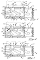
- a first electrical connector 1 is illustrated in Figure 1.
- the first electrical connector 1 comprises an actuating slide 2, which is commonly of U-shaped design when viewed from above, with a handle 3, which is illustrated in section here, and two side walls 4 extending therefrom. As the connector 1 is shown in sectional form, only one of the side walls 4 can be discerned in Figure 1.
- the side wall 4 has two camming slots 5 and 6.
- the side wall 4 of the actuating slide 2 has a latching lug 7 for establishing an entry position ( Figures 1 and 2) and a latching lug 8 for an end position.
- a resilient arm 9 is additionally provided.
- the resilient arm 9 is bounded on one side by a cutout region 10 of in the side wall 4 of the actuating slide 2 and by edge 22 that defines part of the camming slot 6 on the other side.
- the side wall 4 that is not shown would normally have the same basic construction.
- the first connector 1 has a housing 11, in which the actuating slide 2 is arranged.
- This housing 11 has a latching arm 12 with a latching lug 13 that serves to latch the actuating slide 2 in the entry position and in the end position.
- the latching lug 13 interacts with the complementary latching lugs 7 and 8 on the actuating slide 2.
- the latching arm 12 is resilient in the plug-in direction.
- the housing 11 of the first connector 1 has two openings 14 and 15, which serve to introduce the guide pins 18, 19 of a complementary connector 17 into the camming slots 5, 6 of the actuating slide 2.
- the opening 15 is wider than the opening 14.
- a free end 20 of the resilient arm 9 will run up against an edge 16 of the opening 15 in the entry position. As a result, the actuating slide 2 cannot be displaced towards the end position.
- the resilient arm 9 interlocks the actuating slide 2 by interfering with the edge 16 of the opening 15.
- the plug-in direction of the complementary connector 17 is indicated by an Arrow S.
- the complementary connector 17 is introduced with guide pins 18 and 19 passing through the openings 15 and 14 in the housing 11 of the first connector 1 and entering into the camming slots 5 and 6 of the actuating slide 2.
- the guide pin 19 runs up against edge 22 of the resilient arm 9.
- the resilient arm 9 deflects into the material cutout region 10, as indicated by the arrow F, which also specifies the spring direction.
- the interlocking between the actuating slide 2 and the housing 11 of the first connector 1 is defeated, as illustrated in Figure 3.
- the resilient arm 9 is deflected as a result of the pin 19 running up against edge 22 of the resilient arm 9, which edge 22 is formed by the camming slot 6.
- the actuating slide 2 can now be displaced in the actuating direction, which is indicated by an Arrow B in Figure 3, whereby the two connectors 1, 17 can be brought together in the plug-in direction S.
Landscapes
- Details Of Connecting Devices For Male And Female Coupling (AREA)
Claims (4)
- Elektrischer Verbinder (1) für einen Eingriff mit einem komplementären Verbinder (17), mit mindestsens einem Führungsstift (18, 19), der einen Betätigungsschieber (2) mit mindestens einem Führungsschlitz (5, 6) aufweist, wobei der Betätigungsschieber (2) im Verbinder (1) integriert ist und mit dem komplementären Verbinder (17) in Wechselwirkung steht, um die Verbinder in Eingriff zu bringen, wobei der Führungsstift (18, 19) durch den Führungsschlitz (5, 6) während der Betätigung des Betätigungsschieber (2) für den Zweck des Verbindens der Verbinder bewegt wird, und wobei der Führungsstift (18, 19) in der entgegengesetzten Richtung durch den Führungsschlitz (5, 6) während der Betätigung des Betätigungsschiebers (2) für den Zweck des Trennens der Verbinder bewegt wird, wobei Sperrelemente für das Sperren des Betätigungsschiebers (2) in der Eintrittsposition vorhanden sind, in der der Führungsstift (18, 19) in den Führungsschlitz (5, 6) eingeführt werden kann und der Führungsstift (19) als Entriegelungselement des Verbinders (17) in einer derartigen Weise dient, daß, wenn die Verbinder miteinander verbunden werden, die Sperrelemente in einem Ausmaß so entriegelt werden, daß der Betätigungsschieber (2) aus der Eintrittsposition in die Endposition bewegt werden kann, in der die Verbinder in Kontakt sind, dadurch gekennzeichnet, daß die Sperrelemente für das Sperren des Betätigungsschiebers (2) als ein Arm (9) am Betätigungsschieber (2) konstruiert sind, der in der Einsteckrichtung elastisch ist, der an einer Seite durch den Führungsschlitz (6) begrenzt wird und mit einer Öffnung (15) am Verbinder (1) für die Einführung des Führungsstiftes (19) in den Führungsschlitz (16) in Wechselwirkung steht.
- Verbinder nach Anspruch 1, dadurch gekennzeichnet, daß komplementäre Einklinkelemente (7, 8, 13) am Betätigungsschieber (2) und dem Verbinder (1) vorhanden sind, um den Betätigungsschieber (2) in einer ersten Einklinkposition, die der Eintrittsposition entspricht, und in einer zweiten Einklinkposition, der Endposition, einzuklinken.
- Verbinder nach einem der Ansprüche 1 oder 2, dadurch gekennzeichnet, daß der elastische Arm (9) an der anderen Seite durch einen Materialaussparungsabschnitt (10) des Betätigungsschiebers (2) begrenzt wird.
- Verbinder nach einem der Ansprüche 1 bis 3, dadurch gekennzeichnet, daß der Betätigungsschieber (2) im wesentlichen eine U-formige Konstruktion mit zwei Seitenwänden (4) aufweist, in denen die Führungsschlitze (5, 6) angeordnet sind.
Applications Claiming Priority (3)
| Application Number | Priority Date | Filing Date | Title |
|---|---|---|---|
| DE19802554 | 1998-01-23 | ||
| DE19802554A DE19802554A1 (de) | 1998-01-23 | 1998-01-23 | Steckeranorndung mit einem Betätigungsschieber |
| PCT/IB1999/000076 WO1999038230A1 (en) | 1998-01-23 | 1999-01-19 | Connector arrangement with an actuating slide |
Publications (2)
| Publication Number | Publication Date |
|---|---|
| EP1050087A1 EP1050087A1 (de) | 2000-11-08 |
| EP1050087B1 true EP1050087B1 (de) | 2002-04-17 |
Family
ID=7855486
Family Applications (1)
| Application Number | Title | Priority Date | Filing Date |
|---|---|---|---|
| EP99900105A Expired - Lifetime EP1050087B1 (de) | 1998-01-23 | 1999-01-19 | Elektrischer stecker mit einem betätigungsschieber |
Country Status (5)
| Country | Link |
|---|---|
| EP (1) | EP1050087B1 (de) |
| JP (1) | JP4175600B2 (de) |
| AU (1) | AU1779399A (de) |
| DE (2) | DE19802554A1 (de) |
| WO (1) | WO1999038230A1 (de) |
Families Citing this family (6)
| Publication number | Priority date | Publication date | Assignee | Title |
|---|---|---|---|---|
| JP4655960B2 (ja) | 2006-02-24 | 2011-03-23 | 住友電装株式会社 | コネクタ |
| WO2010076592A1 (en) | 2008-12-31 | 2010-07-08 | Fci | Connector arrangement with mate-assist device |
| JP5721473B2 (ja) * | 2011-03-01 | 2015-05-20 | 矢崎総業株式会社 | コネクタ |
| WO2014114324A1 (en) | 2013-01-22 | 2014-07-31 | Delphi International Operations Luxembourg S.À.R.L. | Electrical connector assembly |
| DE102016120063B4 (de) | 2016-10-20 | 2018-07-19 | Rosenberger Hochfrequenztechnik Gmbh & Co. Kg | Steckverbindung |
| CN109149264B (zh) * | 2017-06-28 | 2021-01-29 | 中航光电科技股份有限公司 | 一种连接器组件及其连接器 |
Family Cites Families (3)
| Publication number | Priority date | Publication date | Assignee | Title |
|---|---|---|---|---|
| FR2705503B1 (fr) * | 1993-05-21 | 1995-07-28 | Francelco Sa | Connecteur électrique à tiroir d'insertion et d'extraction. |
| DE19511225C5 (de) * | 1995-03-27 | 2008-02-07 | Robert Bosch Gmbh | Elektrische Steckvorrichtung |
| DE19532623B4 (de) * | 1995-09-04 | 2005-07-28 | The Whitaker Corp., Wilmington | Elektrischer Stecker mit einem Betätigungsschieber |
-
1998
- 1998-01-23 DE DE19802554A patent/DE19802554A1/de not_active Withdrawn
-
1999
- 1999-01-19 EP EP99900105A patent/EP1050087B1/de not_active Expired - Lifetime
- 1999-01-19 JP JP2000529018A patent/JP4175600B2/ja not_active Expired - Fee Related
- 1999-01-19 AU AU17793/99A patent/AU1779399A/en not_active Abandoned
- 1999-01-19 DE DE69901287T patent/DE69901287T2/de not_active Expired - Lifetime
- 1999-01-19 WO PCT/IB1999/000076 patent/WO1999038230A1/en active IP Right Grant
Also Published As
| Publication number | Publication date |
|---|---|
| DE19802554A1 (de) | 1999-08-05 |
| AU1779399A (en) | 1999-08-09 |
| DE69901287D1 (de) | 2002-05-23 |
| WO1999038230A1 (en) | 1999-07-29 |
| JP2002502088A (ja) | 2002-01-22 |
| EP1050087A1 (de) | 2000-11-08 |
| DE69901287T2 (de) | 2002-11-21 |
| JP4175600B2 (ja) | 2008-11-05 |
Similar Documents
| Publication | Publication Date | Title |
|---|---|---|
| KR100946917B1 (ko) | 위치 확정 장치를 구비하는 레버 결합식 커넥터 어셈블리 | |
| US5833484A (en) | Connector with pivotable coupling lever | |
| US5928038A (en) | Electrical connector position assurance system | |
| KR100875066B1 (ko) | 이중 래칭 및 피드백 기능을 갖는 슬라이드 부재를 구비한레버형 전기 커넥터 | |
| KR100198412B1 (ko) | 전방 단부에 단자 위치 확정 장치가 장착된 커넥터 | |
| US7938655B2 (en) | Lever-type connector | |
| EP0726617B1 (de) | Verbinder mit Sekundärverriegelung und Kupplungsvorrichtung | |
| US6475004B2 (en) | Connector assembly with an engagement assist member and connector position assurance device | |
| EP2276123A1 (de) | Verbinder des hebeltyps | |
| JPH1126070A (ja) | レバー嵌合式コネクタ | |
| EP0976175B1 (de) | Verbinder mit sekondärverriegelung und kupplungsvorrichtung | |
| CN114122838A (zh) | 具有插接连接器和配合插接连接器的连接装置 | |
| US20030017733A1 (en) | Connector | |
| EP0660451B1 (de) | Steckverbinder | |
| EP1905134B1 (de) | Elektrischer verbinder | |
| US5919053A (en) | Connector engaging structure | |
| EP1050087B1 (de) | Elektrischer stecker mit einem betätigungsschieber | |
| JP3956159B2 (ja) | 電気コネクタ | |
| KR100446796B1 (ko) | 커넥터 | |
| US5975930A (en) | Slide fit connector | |
| JP3457172B2 (ja) | コネクタ嵌合構造 | |
| EP2362974B1 (de) | Verbindungshilfe mit exzentrischem hebel | |
| WO2002073749A1 (en) | Lever type electrical connector | |
| EP0903812B1 (de) | Steckverbindergehäuse mit sekondärer Verriegelung | |
| US5876254A (en) | Apparatus for securing contacts in a contact housing |
Legal Events
| Date | Code | Title | Description |
|---|---|---|---|
| PUAI | Public reference made under article 153(3) epc to a published international application that has entered the european phase |
Free format text: ORIGINAL CODE: 0009012 |
|
| 17P | Request for examination filed |
Effective date: 20000721 |
|
| AK | Designated contracting states |
Kind code of ref document: A1 Designated state(s): DE FR GB |
|
| GRAG | Despatch of communication of intention to grant |
Free format text: ORIGINAL CODE: EPIDOS AGRA |
|
| 17Q | First examination report despatched |
Effective date: 20010402 |
|
| GRAG | Despatch of communication of intention to grant |
Free format text: ORIGINAL CODE: EPIDOS AGRA |
|
| GRAH | Despatch of communication of intention to grant a patent |
Free format text: ORIGINAL CODE: EPIDOS IGRA |
|
| REG | Reference to a national code |
Ref country code: GB Ref legal event code: IF02 |
|
| GRAA | (expected) grant |
Free format text: ORIGINAL CODE: 0009210 |
|
| AK | Designated contracting states |
Kind code of ref document: B1 Designated state(s): DE FR GB |
|
| REF | Corresponds to: |
Ref document number: 69901287 Country of ref document: DE Date of ref document: 20020523 |
|
| ET | Fr: translation filed | ||
| PLBE | No opposition filed within time limit |
Free format text: ORIGINAL CODE: 0009261 |
|
| STAA | Information on the status of an ep patent application or granted ep patent |
Free format text: STATUS: NO OPPOSITION FILED WITHIN TIME LIMIT |
|
| 26N | No opposition filed |
Effective date: 20030120 |
|
| PGFP | Annual fee paid to national office [announced via postgrant information from national office to epo] |
Ref country code: GB Payment date: 20031211 Year of fee payment: 6 |
|
| PG25 | Lapsed in a contracting state [announced via postgrant information from national office to epo] |
Ref country code: GB Free format text: LAPSE BECAUSE OF NON-PAYMENT OF DUE FEES Effective date: 20050119 |
|
| GBPC | Gb: european patent ceased through non-payment of renewal fee |
Effective date: 20050119 |
|
| REG | Reference to a national code |
Ref country code: FR Ref legal event code: PLFP Year of fee payment: 18 |
|
| REG | Reference to a national code |
Ref country code: FR Ref legal event code: PLFP Year of fee payment: 19 |
|
| REG | Reference to a national code |
Ref country code: FR Ref legal event code: PLFP Year of fee payment: 20 |
|
| PGFP | Annual fee paid to national office [announced via postgrant information from national office to epo] |
Ref country code: FR Payment date: 20171211 Year of fee payment: 20 |
|
| PGFP | Annual fee paid to national office [announced via postgrant information from national office to epo] |
Ref country code: DE Payment date: 20180110 Year of fee payment: 20 |
|
| REG | Reference to a national code |
Ref country code: DE Ref legal event code: R071 Ref document number: 69901287 Country of ref document: DE |