EP1048770A1 - Zungennadel mit auf einem Zapfen gelagerter Zunge - Google Patents
Zungennadel mit auf einem Zapfen gelagerter Zunge Download PDFInfo
- Publication number
- EP1048770A1 EP1048770A1 EP00105150A EP00105150A EP1048770A1 EP 1048770 A1 EP1048770 A1 EP 1048770A1 EP 00105150 A EP00105150 A EP 00105150A EP 00105150 A EP00105150 A EP 00105150A EP 1048770 A1 EP1048770 A1 EP 1048770A1
- Authority
- EP
- European Patent Office
- Prior art keywords
- tongue
- needle according
- latch needle
- recess
- groove
- Prior art date
- Legal status (The legal status is an assumption and is not a legal conclusion. Google has not performed a legal analysis and makes no representation as to the accuracy of the status listed.)
- Granted
Links
- 230000007704 transition Effects 0.000 claims description 8
- 239000000463 material Substances 0.000 claims description 3
- 230000015572 biosynthetic process Effects 0.000 abstract description 5
- 210000000481 breast Anatomy 0.000 description 2
- 230000001419 dependent effect Effects 0.000 description 2
- 238000013459 approach Methods 0.000 description 1
- 230000001427 coherent effect Effects 0.000 description 1
- 238000009940 knitting Methods 0.000 description 1
- 238000004519 manufacturing process Methods 0.000 description 1
- 230000035515 penetration Effects 0.000 description 1
- 238000000926 separation method Methods 0.000 description 1
Images




Classifications
-
- D—TEXTILES; PAPER
- D04—BRAIDING; LACE-MAKING; KNITTING; TRIMMINGS; NON-WOVEN FABRICS
- D04B—KNITTING
- D04B35/00—Details of, or auxiliary devices incorporated in, knitting machines, not otherwise provided for
- D04B35/02—Knitting tools or instruments not provided for in group D04B15/00 or D04B27/00
- D04B35/04—Latch needles
Definitions
- the invention relates to a latch needle with the features of the preamble of claim 1.
- Such Switch needles are used in knitting machines, for example.
- Tongue needles have a hook-shaped head, the a pivotally mounted tongue is assigned. This can swivel into a first position in which they are on the free End of the hook-shaped head, as well as in a second Position in which it is pivoted away from the head and releases the head.
- the precise positioning of the tongue comes important in doing so.
- the tongue has to run smoothly to be swung back and forth by low operating forces to be able to.
- her tongue spoon when closing hits the hook of the latch needle. This has to go beyond the Lifetime of the latch needle, and therefore over many Working games away, remain ensured.
- the tongue is stored on the latch needle in usually through a pin or axle pin through a Tongue hole provided in the tongue shaft engages.
- a cheek area near the head formed which has a tongue slot.
- Cheeks are provided on the sides of the tongue slot which a corresponding pin is formed or between which has a corresponding axle pin.
- the tongue protrudes between the cheeks in the tongue slot and is mounted on the pin or axle pin.
- Cheeks formed holes are different approaches known.
- E.g. is from the US PS 3,526,104 and that belonging to the same patent family DE-OS 15 85 091 a latch needle with an inserted Axle pin known.
- the holes used to receive the axle pin are provided in the cheek of the latch needle, are aligned with each other and are to the side faces of the Needle flared.
- the axle pin used is formed by a piece of wire on both ends is riveted, so that convex rivet heads form.
- the axle pin is provided by a separately and piece of wire inserted into the corresponding holes educated.
- a latch needle is known from US Pat. No. 5,509,280 known for storing the tongue two diagonally adjacent, from the cheeks or cheeks half pins pushed out serve.
- the half cones are asymmetrical with respect to the pivot axis of the tongue shaped.
- the half cones are formed by the Cheeks plastic with an appropriate piercing tool be deformed. The penetration depth is along the Circumference of each peg is not constant, reducing the flow conditions of the material vary along the circumference.
- half pin for storing a tongue on a latch needle plastic deformation of the cheeks on both sides of the tongue slot to manufacture.
- piercing tools used with a flat face.
- the piercing tools have a cylindrical at their respective front ends Cutters with a flat end surface whose diameter is smaller than the diameter of the half pin to be produced.
- the half-pegs form projections into the tongue slot protrude and reach into the tongue hole.
- the resulting half-cones are permanent ensure precise positioning of the tongue.
- the load-bearing component is 100% of the tongue thickness.
- the latch needle according to the invention points to the latching at least one generated by plastic deformation Projection on the tongue slot and in the Tongue hole one extending into the tongue slot Tongue sticks out.
- the projection thus forms a pin or a half pin for storing the tongue.
- the needle On the side surface the needle is in the axial extension of the recess a further, second depression available, which is preferably extends and interrupted along the circumference or can be divided. This additional deepening influences the material flow during formation or Form the projection positively, which is a tenon or half tenon forms. In this way it becomes possible to have a spigot or half-cones with only a slight bulge of the To generate the end face of the projection. This succeeds to keep the face of the protrusion relatively flat, so that the lateral surface used for tongue storage can be maximized in size.
- the height of this lateral surface is ideally equal to the tongue thickness.
- the resulting cones abut each other in the middle of the tongue slot.
- the gap between the Mantle surface of the two pins, i.e. those in this area existing approximately circular interruption of the storage area minimized. This is regardless of whether the half pin (Projections) welded together at their end faces are or not.
- the maximization of the storage area achieved and the slight deformation of the inner flanks of the tongue slot allow permanent precise, i.e. low backlash, Tongue storage, so that also tongue needles, the very are in operation for a long time, work with high precision.
- the floor can be a continuous and uninterrupted Have groove and otherwise curved or be trained.
- the groove second deepening
- the groove can directly on the wall of the first recess connect. It is then arranged radially on the outside. It however, it is also possible to arrange them a little further inside and an annular step between the wall of the first Form deepening and the groove.
- the middle area can be a step-like transition area be trained. This can be used as a conical ring surface or as a real step with an almost cylindrical ring surface be shaped.
- the one in the bottom of the first depression The provided annular groove can have a groove bottom and groove flanks have, which merge with a radius. This radius is preferably significantly smaller than that half the groove width, preferably less than a third or a quarter of the groove width. The radius is dependent from the latch needle.
- the central region of the first depression is preferred flat. However, it can also be concavely curved in some areas or be provided with further depressions.
- Essential is for the formation of the wells according to the invention, that there is an outside area that is deeper is as a middle area. The outside area does not have to be annularly coherent.
- the wells with an essentially cylindrical lateral surface to train are advantageously about the size of the diameter of the Projection (pin / half pin). However, it can also be useful be slightly different diameters.
- the protrusion is formed from the respective cheek and preferably connected to it. This Connection prevents separation of the projection (pin) from the remaining latch needle even after a long period of use.
- a tongue needle 1 is illustrated in detail in FIG. It has a shaft 2, which ultimately carries a hook-shaped head 3. Between the head 3 and the shaft 2 is a somewhat bulging section provided that forms a breast 4. This is used for attachment a tongue 5, which can be seen from FIG Axis of rotation 6 is pivotally mounted. The tongue 5 engages with its tongue shaft 10 in a tongue slot 7, which penetrates the needle breast and in two side cheeks 8, 9 divided.
- the Half pins 11, 12 For storing the tongue 5 around the transverse to the shaft 2 Aligned axis of rotation 6 (see Figure 2) serve half pin 11, 12, which are connected to the cheeks 8, 9.
- the Half pins 11, 12 thus jointly form a bearing 13 for the tongue 5 and its tongue shaft 10, as in FIG. 3 can be seen.
- This has a tongue hole 14 in the half pin 11, 12 from both flat sides of the tongue shaft 10 intervene here.
- The is approximately in the middle Bearing surface 15 interrupted by a gap 16 in which the half pins 11, 12 closely adjacent with their end faces end to each other or abut each other.
- the storage area 15 is thereby divided into individual partial areas 15, 15b, the partial surface 15a is the lateral surface of the half pin 11 and the partial surface 15b the lateral surface of the Half pin is 12.
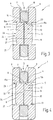
- the geometry is again shown in detail in FIG. 7 illustrated. Thereafter, the end face 17 is essentially formed plan and the partial surface 15a is essentially cylindrical. A transition area 21 between the end face 17 and the partial surface 15a has a certain Curvature or curvature. On an ideal cylinder shape a dashed illustration in FIG. 7 is missing Area 22. Ideally, it is not very small.
- the recess 24 is in axial Extension of the half pin 11 with a recess 24 formed essentially cylindrical outer surface 25.
- the lateral surface has approximately the same diameter like the half pin 11.
- the recess 24 has a bottom 26 with at least one further recess 20, i.e. on Middle region 27 is located on the periphery of the Floor 26 surrounding outer area 28 in front.
- the location of the second recess 20 is in the edge region of the tongue hole 14 arranged.
- the second recess 20 is an annular groove formed and has, as can be seen particularly in FIG. 7, a substantially flat groove bottom 29 on which is followed on the outside by a groove flank, which through the Shell surface or wall 25 can be formed.
- the transition between the groove bottom 29 and the wall 25 formed by a curved surface area 31, the one has a relatively small radius.
- a conical groove flank 32 (Ring surface) provided with a curved surface area 33 merges into the groove bottom 29.
- the area 33 is preferably also with a small radius of curvature curved.
- the cheek 8 faces the tongue slot 7 Side of a substantially flat flank 36, which reaches up to the partial surface 15a of the half pin 11.
- the tongue 5 is through the corresponding flanks of the tongue slot 7 so that they, although they can be pivoted with little friction about the axis of rotation 6 (FIG. 2), can hardly tip in the lateral direction.
- the relatively large area Guiding the tongue 5 enables a permanent precise work. This also applies to the storage formed by the half pin 11, 12.
- the storage area 15 is almost closed, i.e. the gap is 16 ideally zero.
- the half pins 11, 12 are part of the cheeks 8, 9. They are due to plastic deformation of cheeks 8, 9 educated.
- the half pins 11, 12 can be used if necessary their end faces 17, 18 are welded together. This can be done with the help of a laser beam that is in the recess 24 hits.
- the half pins 11, 12 are preferably in relation to one another mirror-symmetrical, so that the above, on the half pin 11 related description equally the half pin 12 applies. In other embodiments there is no mirror-symmetrical structure of the half pin.
- FIG Figure 5 Another embodiment of the latch needle 1 is shown in FIG Figure 5 illustrates.
- the difference to the embodiments according to Figures 3 and 4 is again in the Formation of the deepening 24.
- the wall 25 of the depression is approximately cylindrical and agrees with the diameter of the partial surface 15a of the half pin 11 essentially coincide.
- the half pin 12 Deviating from the Embodiments described above is the bottom 25 of the depression, however, arched overall. His middle section 27 goes without a paragraph in the second recess 20 in Outside area 28, which is not a groove, but the Edge of a spherically convex surface.
- the Transition between the second recess 20 and the wall 25 is formed by the surface area 31, the one has a very small radius of curvature.
- This one too Embodiment it is possible in the tongue slot 7 almost flat flanks 36 and almost cylindrical partial surfaces 15a, 15b on the half pin 11, 12 to get. in the the rest of the above description applies accordingly.
- a latch needle has half-journals for storing its tongue 11, 12, which are integrally formed on the latch needle.
- the latch needle 1 is provided with a latch slot 7, which is delimited by two cheeks 8, 9. At each other are facing side surfaces of the cheeks 8, 9 Wells trained.
- the through plastic deformation formed recesses produce projections or half-pegs 11 and 12, which in the tongue slot 7 and in Tongue hole extending into the tongue slot 7 Tongue 5 protrude.
- the bottom of the recess 24 has in its Edge area in the axial extension of a further depression 20 on. This form of two-tiered deepening allows the formation of a relatively precise cylindrical Half pin 11, 12, so that the bearing portion of the through the two half journals 11, 12 defined bearing surface 15 is maximized.
Landscapes
- Engineering & Computer Science (AREA)
- Textile Engineering (AREA)
- Knitting Machines (AREA)
- Infusion, Injection, And Reservoir Apparatuses (AREA)
Abstract
Description
Claims (17)
- Zungennadel (1)mit einem Kopf (3), dem eine schwenkbar gelagerten Zunge (5) zugeordnet ist, und mit einer Nadelbrust (4), die mit einem zwischen zwei Wangen (8, 9) ausgebildeten Zungenschlitz (7) versehen ist,
wobei die Zunge (5) einen Zungenschaft (6) aufweist, der mit einem Zungenloch (14) versehen ist und sich in den Zungenschlitz (7) erstreckt,mit wenigstens einer Zungenlagerung (13), die aus wenigstens einem durch plastische Verformung aus einer der Wangen (8, 9) herausgebildeten Vorsprung (11, 12) gebildet ist, die in dem Zungenloch (14) angeordnet sind, wobei die Wange (8, 9) eine Vertiefung (24) enthält, aus deren Material der wenigstens eine Vorsprung (11, 12) gebildet wird,
dadurch gekennzeichnet,dass die Vertiefung (24) einen Boden (26) aufweist, der eine weitere Vertiefung (20) im Außenbereich (28) aufweist. - Zungennadel nach Anspruch 1, dadurch gekennzeichnet, dass die Vertiefung (24) eine im Wesentlichen zylinderförmige Wandung (25) aufweist.
- Zungennadel nach Anspruch 1, dadurch gekennzeichnet, dass der Boden (26) eine zweite Vertiefung (20) im ringförmigen Außenbereich (28) und einen Mittelbereich (27) aufweist, wobei die zweite Vertiefung (20) eine größere Tiefe aufweist als die erste Vertiefung in dem Mittelbereich (27).
- Zungennadel nach Anspruch 3, dadurch gekennzeichnet, dass die zweite Vertiefung (20) zusammenhängend ausbildet ist.
- Zungennadel nach Anspruch 3, dadurch gekennzeichnet, dass der Mittelbereich (27) plan ausgebildet ist.
- Zungennadel nach Anspruch 3, dadurch gekennzeichnet, dass der Mittelbereich (27) gewölbt ausgebildet ist.
- Zungennadel nach Anspruch 3, dadurch gekennzeichnet, dass zwischen dem Mittelbereich (27) und der zweiten Vertiefung (20) ein stufenartiger Übergangsbereich mit einer konischen Ringfläche (32) angeordnet ist.
- Zungennadel nach Anspruch 3, dadurch gekennzeichnet, dass die Breite der zweiteVertiefung (20) ihre Tiefe übersteigt.
- Zungennadel nach Anspruch 1, dadurch gekennzeichnet, dass die zweite Vertiefung (20) eine Ringnut mit Nutboden (29), Mantelfläche (25) und Nutflanke (32) ist und dass jeweils im Übergang von dem Nutboden (29) zu der Mantelfläche (25) und der Nutflanke (32) ein gewölbter Flächenbereich (31, 33) vorgesehen ist, dessen Krümmungsradius geringer ist als die halbe Nutbreite.
- Zungennadel nach Anspruch 1, dadurch gekennzeichnet, dass die zweite Vertiefung (20) eine Ringnut mit Nutboden (29), Mantelfläche (25) und Nutflanken (32) ist und dass jeweils im Übergang von dem Nutboden (29) zu der Mantelfläche (25) bzw. der Nutflanke (32) ein gewölbter Flächenbereich (31) vorgesehen ist, dessen Krümmungsradius geringer ist als ein Drittel, vorzugsweise ein Viertel der Nutbreite.
- Zungennadel nach Anspruch 3, dadurch gekennzeichnet, dass die Tiefe der Vertiefung (24) gemessen im Mittelbereich (27) im Wesentlichen der Höhe des Vorsprungs (11, 12) entspricht.
- Zungennadel nach Anspruch 1, dadurch gekennzeichnet, dass die Zungenlagerung (13) durch zwei jeweils mit einem der Wangen (8, 9) verbundene Vorsprünge (11, 12) gebildet ist.
- Zungennadel nach Anspruch 12, dadurch gekennzeichnet, dass die Vorsprünge eine zylinderförmige Mantelfläche (15) festlegen, die eine Lagerfläche für die Zunge (5) ist.
- Zungennadel nach Anspruch 12, dadurch gekennzeichnet, dass die Vorsprünge im wesentlichen plane Stirnflächen (17, 18) aufweisen, die einander vorzugsweise berühren.
- Zungennadel nach Anspruch 1, dadurch gekennzeichnet, dass die Stirnflächen (17, 18) im Wesentlichen parallel zu den Wangen (8, 9) angeordnet sind.
- Zungennadel nach Anspruch 1, dadurch gekennzeichnet, dass die Stirnflächen (17, 18) mit den Wangen (8, 9) einen von Null verschiedenen Winkel einschließen.
- Zungennadel nach Anspruch 1, dadurch gekennzeichnet, dass die zweite Vertiefung (20) im Wesentlichen in einem Bereich angeordnet ist, der dem Randbereich des Zungenlochs (14) entspricht.
Applications Claiming Priority (2)
| Application Number | Priority Date | Filing Date | Title |
|---|---|---|---|
| DE19914928 | 1999-04-01 | ||
| DE19914928A DE19914928C2 (de) | 1999-04-01 | 1999-04-01 | Zungennadel mit auf einem Zapfen gelagerter Zunge |
Publications (2)
| Publication Number | Publication Date |
|---|---|
| EP1048770A1 true EP1048770A1 (de) | 2000-11-02 |
| EP1048770B1 EP1048770B1 (de) | 2004-07-28 |
Family
ID=7903292
Family Applications (1)
| Application Number | Title | Priority Date | Filing Date |
|---|---|---|---|
| EP00105150A Expired - Lifetime EP1048770B1 (de) | 1999-04-01 | 2000-03-10 | Zungennadel mit auf einem Zapfen gelagerter Zunge |
Country Status (5)
| Country | Link |
|---|---|
| US (1) | US6209360B1 (de) |
| EP (1) | EP1048770B1 (de) |
| JP (1) | JP2000303332A (de) |
| DE (2) | DE19914928C2 (de) |
| ES (1) | ES2220278T3 (de) |
Families Citing this family (1)
| Publication number | Priority date | Publication date | Assignee | Title |
|---|---|---|---|---|
| TWI744856B (zh) * | 2020-04-09 | 2021-11-01 | 大康織機股份有限公司 | 導襪針組 |
Citations (4)
| Publication number | Priority date | Publication date | Assignee | Title |
|---|---|---|---|---|
| DE608619C (de) * | 1935-01-28 | Torrington Co | Verfahren zur Herstellung von Strickmaschinennadeln | |
| US4020319A (en) * | 1974-02-07 | 1977-04-26 | The Torrington Company | Method of forming a knitting needle latch pivot |
| GB1588410A (en) * | 1977-12-13 | 1981-04-23 | Needle Industries Ltd | Latched needles |
| US5509280A (en) * | 1994-01-29 | 1996-04-23 | Theodor Groz & Sohne & Ernst Beckert | Latch needle for textile machines |
Family Cites Families (7)
| Publication number | Priority date | Publication date | Assignee | Title |
|---|---|---|---|---|
| CA681690A (en) * | 1964-03-10 | C. Oberem William | Welded integral bearing for knitting machine latch needles | |
| US1961429A (en) * | 1931-06-15 | 1934-06-05 | Torrington Co | Latch needle and method of making the same |
| US1991140A (en) * | 1934-02-28 | 1935-02-12 | Acme Knitting Machine & Needle | Knitting machine needle |
| US3022651A (en) * | 1958-02-26 | 1962-02-27 | Torrington Co | Integral offset bearing for latch of knitting needle |
| GB1098578A (en) * | 1965-12-08 | 1968-01-10 | Grieve & Company Ltd T | Improvements in and relating to latch needles |
| FR1499561A (fr) * | 1966-10-28 | 1967-10-27 | Grieve & Company Ltd T | Aiguille à bec à rivet pressé |
| US3850011A (en) * | 1972-06-23 | 1974-11-26 | Torrington Co | Latch pivot for latch needle |
-
1999
- 1999-04-01 DE DE19914928A patent/DE19914928C2/de not_active Expired - Fee Related
-
2000
- 2000-03-10 ES ES00105150T patent/ES2220278T3/es not_active Expired - Lifetime
- 2000-03-10 DE DE50007170T patent/DE50007170D1/de not_active Expired - Lifetime
- 2000-03-10 EP EP00105150A patent/EP1048770B1/de not_active Expired - Lifetime
- 2000-03-29 JP JP2000090249A patent/JP2000303332A/ja active Pending
- 2000-03-30 US US09/537,545 patent/US6209360B1/en not_active Expired - Lifetime
Patent Citations (4)
| Publication number | Priority date | Publication date | Assignee | Title |
|---|---|---|---|---|
| DE608619C (de) * | 1935-01-28 | Torrington Co | Verfahren zur Herstellung von Strickmaschinennadeln | |
| US4020319A (en) * | 1974-02-07 | 1977-04-26 | The Torrington Company | Method of forming a knitting needle latch pivot |
| GB1588410A (en) * | 1977-12-13 | 1981-04-23 | Needle Industries Ltd | Latched needles |
| US5509280A (en) * | 1994-01-29 | 1996-04-23 | Theodor Groz & Sohne & Ernst Beckert | Latch needle for textile machines |
Also Published As
| Publication number | Publication date |
|---|---|
| DE50007170D1 (de) | 2004-09-02 |
| ES2220278T3 (es) | 2004-12-16 |
| US6209360B1 (en) | 2001-04-03 |
| DE19914928A1 (de) | 2000-10-05 |
| DE19914928C2 (de) | 2001-05-23 |
| JP2000303332A (ja) | 2000-10-31 |
| EP1048770B1 (de) | 2004-07-28 |
Similar Documents
| Publication | Publication Date | Title |
|---|---|---|
| DE69713790T2 (de) | Werkzeug für spanabnehmende bearbeitung | |
| DE102010025653B4 (de) | Rotations-Schneidwerkzeug | |
| DE2822548C2 (de) | Werkzeug, insbesondere Bergbaumeißel, mit einem Halteschaft zur Befestigung in einem Aufnahmeteil einer Maschine | |
| AT396762B (de) | Innendrehmeissel | |
| DE4422342A1 (de) | Lochschneider-Verbindungsvorrichtung und Lochschneider | |
| CH616355A5 (de) | ||
| WO1998007539A1 (de) | Schneideinsatz zum bohren und bohrwerkzeug | |
| DE4032176C2 (de) | Scheibenschneider | |
| DE3784343T2 (de) | Einsatz fuer bohrwerkzeuge. | |
| DE69101285T2 (de) | Bohrwerkzeug. | |
| DE2832653A1 (de) | Kugelfingerfraeser | |
| DE1752026A1 (de) | Reversible Bohrlochraeumnadel | |
| DE102006014602A1 (de) | Zerspanwerkzeug umfassend einen lösbaren Zerspankopf | |
| DE112019006105B4 (de) | Bohrer und Einsatz für Bohrer mit verbesserter Zentrierfähigkeit und Schneidleistung | |
| DE3126355C2 (de) | Bohrschraube | |
| DE3143462C2 (de) | ||
| EP2218813B1 (de) | Nadelhalterung für eine Textilmaschine | |
| DE3600620C1 (de) | ||
| DE60110920T2 (de) | Maschinenkolbenherstellung | |
| WO2001038029A1 (de) | Kugelbahnfräser und schneidplatte hierfür | |
| DE102019108429A1 (de) | Modulares rotierendes schneidwerkzeug mit schneidkopf, der bohr-/reibabschnitte aufweist | |
| DE2949643A1 (de) | Zylinderschloss | |
| DE60300603T2 (de) | Bohrer mit Scheindeinsatz | |
| EP1048770B1 (de) | Zungennadel mit auf einem Zapfen gelagerter Zunge | |
| EP2224048B1 (de) | Zungennadel mit drehendem Achsstift |
Legal Events
| Date | Code | Title | Description |
|---|---|---|---|
| PUAI | Public reference made under article 153(3) epc to a published international application that has entered the european phase |
Free format text: ORIGINAL CODE: 0009012 |
|
| AK | Designated contracting states |
Kind code of ref document: A1 Designated state(s): AT BE CH CY DE DK ES FI FR GB GR IE IT LI LU MC NL PT SE |
|
| AX | Request for extension of the european patent |
Free format text: AL;LT;LV;MK;RO;SI |
|
| 17P | Request for examination filed |
Effective date: 20001124 |
|
| AKX | Designation fees paid |
Free format text: DE ES FR GB IT |
|
| 17Q | First examination report despatched |
Effective date: 20030217 |
|
| GRAP | Despatch of communication of intention to grant a patent |
Free format text: ORIGINAL CODE: EPIDOSNIGR1 |
|
| GRAS | Grant fee paid |
Free format text: ORIGINAL CODE: EPIDOSNIGR3 |
|
| GRAA | (expected) grant |
Free format text: ORIGINAL CODE: 0009210 |
|
| AK | Designated contracting states |
Kind code of ref document: B1 Designated state(s): DE ES FR GB IT |
|
| REG | Reference to a national code |
Ref country code: GB Ref legal event code: FG4D Free format text: NOT ENGLISH |
|
| GBT | Gb: translation of ep patent filed (gb section 77(6)(a)/1977) |
Effective date: 20040728 |
|
| REF | Corresponds to: |
Ref document number: 50007170 Country of ref document: DE Date of ref document: 20040902 Kind code of ref document: P |
|
| REG | Reference to a national code |
Ref country code: ES Ref legal event code: FG2A Ref document number: 2220278 Country of ref document: ES Kind code of ref document: T3 |
|
| ET | Fr: translation filed | ||
| PLBE | No opposition filed within time limit |
Free format text: ORIGINAL CODE: 0009261 |
|
| STAA | Information on the status of an ep patent application or granted ep patent |
Free format text: STATUS: NO OPPOSITION FILED WITHIN TIME LIMIT |
|
| 26N | No opposition filed |
Effective date: 20050429 |
|
| PGFP | Annual fee paid to national office [announced via postgrant information from national office to epo] |
Ref country code: FR Payment date: 20120403 Year of fee payment: 13 |
|
| PGFP | Annual fee paid to national office [announced via postgrant information from national office to epo] |
Ref country code: DE Payment date: 20120331 Year of fee payment: 13 |
|
| PGFP | Annual fee paid to national office [announced via postgrant information from national office to epo] |
Ref country code: GB Payment date: 20120322 Year of fee payment: 13 |
|
| PGFP | Annual fee paid to national office [announced via postgrant information from national office to epo] |
Ref country code: IT Payment date: 20120330 Year of fee payment: 13 |
|
| PGFP | Annual fee paid to national office [announced via postgrant information from national office to epo] |
Ref country code: ES Payment date: 20120327 Year of fee payment: 13 |
|
| GBPC | Gb: european patent ceased through non-payment of renewal fee |
Effective date: 20130310 |
|
| REG | Reference to a national code |
Ref country code: FR Ref legal event code: ST Effective date: 20131129 |
|
| REG | Reference to a national code |
Ref country code: DE Ref legal event code: R119 Ref document number: 50007170 Country of ref document: DE Effective date: 20131001 |
|
| PG25 | Lapsed in a contracting state [announced via postgrant information from national office to epo] |
Ref country code: GB Free format text: LAPSE BECAUSE OF NON-PAYMENT OF DUE FEES Effective date: 20130310 Ref country code: FR Free format text: LAPSE BECAUSE OF NON-PAYMENT OF DUE FEES Effective date: 20130402 Ref country code: DE Free format text: LAPSE BECAUSE OF NON-PAYMENT OF DUE FEES Effective date: 20131001 |
|
| PG25 | Lapsed in a contracting state [announced via postgrant information from national office to epo] |
Ref country code: IT Free format text: LAPSE BECAUSE OF NON-PAYMENT OF DUE FEES Effective date: 20130310 |
|
| REG | Reference to a national code |
Ref country code: ES Ref legal event code: FD2A Effective date: 20140606 |
|
| PG25 | Lapsed in a contracting state [announced via postgrant information from national office to epo] |
Ref country code: ES Free format text: LAPSE BECAUSE OF NON-PAYMENT OF DUE FEES Effective date: 20130311 |