EP1047963B1 - Optical film with sharpened bandedge - Google Patents
Optical film with sharpened bandedge Download PDFInfo
- Publication number
- EP1047963B1 EP1047963B1 EP99901387A EP99901387A EP1047963B1 EP 1047963 B1 EP1047963 B1 EP 1047963B1 EP 99901387 A EP99901387 A EP 99901387A EP 99901387 A EP99901387 A EP 99901387A EP 1047963 B1 EP1047963 B1 EP 1047963B1
- Authority
- EP
- European Patent Office
- Prior art keywords
- optical
- thickness
- repeating unit
- along
- optical repeating
- Prior art date
- Legal status (The legal status is an assumption and is not a legal conclusion. Google has not performed a legal analysis and makes no representation as to the accuracy of the status listed.)
- Expired - Lifetime
Links
Images


Classifications
-
- B—PERFORMING OPERATIONS; TRANSPORTING
- B29—WORKING OF PLASTICS; WORKING OF SUBSTANCES IN A PLASTIC STATE IN GENERAL
- B29D—PRODUCING PARTICULAR ARTICLES FROM PLASTICS OR FROM SUBSTANCES IN A PLASTIC STATE
- B29D11/00—Producing optical elements, e.g. lenses or prisms
- B29D11/0074—Production of other optical elements not provided for in B29D11/00009- B29D11/0073
- B29D11/00788—Producing optical films
-
- G—PHYSICS
- G02—OPTICS
- G02B—OPTICAL ELEMENTS, SYSTEMS OR APPARATUS
- G02B5/00—Optical elements other than lenses
- G02B5/20—Filters
- G02B5/28—Interference filters
- G02B5/281—Interference filters designed for the infrared light
- G02B5/282—Interference filters designed for the infrared light reflecting for infrared and transparent for visible light, e.g. heat reflectors, laser protection
-
- G—PHYSICS
- G02—OPTICS
- G02B—OPTICAL ELEMENTS, SYSTEMS OR APPARATUS
- G02B5/00—Optical elements other than lenses
- G02B5/20—Filters
- G02B5/28—Interference filters
- G02B5/285—Interference filters comprising deposited thin solid films
- G02B5/287—Interference filters comprising deposited thin solid films comprising at least one layer of organic material
-
- G—PHYSICS
- G02—OPTICS
- G02B—OPTICAL ELEMENTS, SYSTEMS OR APPARATUS
- G02B5/00—Optical elements other than lenses
- G02B5/30—Polarising elements
- G02B5/3025—Polarisers, i.e. arrangements capable of producing a definite output polarisation state from an unpolarised input state
- G02B5/3033—Polarisers, i.e. arrangements capable of producing a definite output polarisation state from an unpolarised input state in the form of a thin sheet or foil, e.g. Polaroid
- G02B5/3041—Polarisers, i.e. arrangements capable of producing a definite output polarisation state from an unpolarised input state in the form of a thin sheet or foil, e.g. Polaroid comprising multiple thin layers, e.g. multilayer stacks
- G02B5/305—Polarisers, i.e. arrangements capable of producing a definite output polarisation state from an unpolarised input state in the form of a thin sheet or foil, e.g. Polaroid comprising multiple thin layers, e.g. multilayer stacks including organic materials, e.g. polymeric layers
Definitions
- the present invention relates generally to multilayer optical bodies, and in particular to multilayer films exhibiting a sharpened reflective bandedge.
- multilayer reflective films comprising alternating layers of two or more polymers to reflect light is known and is described, for example, in U.S. Patent No. 3,711,176 (Alfrey, Jr. et al.), U.S. Patent No. 5,103,337 (Schrenk et al.), WO 96/19347, and WO 95/17303.
- the reflection and transmission spectra of a particular multilayer film depends primarily on the optical thickness of the individual layers, which is defined as the product of the actual thickness of a layer times its refractive index.
- a multilayer film can be designed that reflects light over a broad band of wavelengths. This band is commonly referred to as the reflection band or stop band.
- a reflection band it is desirable for a reflection band to have a sharp spectral edge at the long wavelength (red) and/or short wavelength (blue) side.
- the reflective films known to the art that contain an optical repeating unit of varying optical thickness typically have moderately sloped bandedges which cause reflections outside of the desired wavelengths of interest.
- a reflective film is designed to reflect infrared light while being transparent over the visible spectrum, a sloped edge on the blue side of the reflection band may encroach into the visible region of the spectrum, thereby resulting in unwanted coloring of the infrared reflective film body.
- Such coloring can be avoided by designing the infrared film such that the infrared reflection band is moved further into the infrared region, but this results in substantial transmission of infrared light near the visible region of the spectrum.
- a reflective film or other optical body that reflects light over a selected range in the visible region of the spectrum, e.g., a reflective film that reflects only green light. In such a case, it may be desirable to have sharp edges at both the red and blue sides of the reflection band.
- US-A-5,360,659 describes a two component infrared reflecting film comprising alternating layers of first (A) and second (B) diverse polymeric materials, said first and second polymeric materials differing in refractive index by at least about 0.03, wherein said first and second polymeric materials have a six alternating layer repeating unit with relative optical thicknesses of about .778A.111B.111A.778B.1-11A.111B, wherein at least 50% of visible light of wavelengths of between about 380-770 nm incident on said film is transmitted and at least 50% of infrared light of wavelengths of between about 770-2000 nm is reflected.
- WO 94/10 589 formable multilayer reflective polymeric body which has a substantially uniform broad bandwidth reflectance over substantially the entire range of the visible spectrum to provide a substantially uniform reflective appearance.
- the body includes at least first and second diverse polymeric materials, the body comprising a sufficient number of alternating layers of the first and second polymeric materials such that at least 40 percent of visible light incident on the body is reflected.
- a substantial majority of the individual layers of the body have optical thicknesses in the range where the sum of the optical thicknesses in a repeating unit of the polymeric materials is greater than about 190 nm, and the first and second polymeric materials differ from each other in refractive index by at least 0.03.
- the present invention provides reflective films and other optical bodies which exhibit sharp bandedges on one or both sides of the main reflection bands.
- the optical bodies of the present invention comprise multilayer stacks M 1 and M 2 , each having first order reflections in a desired part of the spectrum and comprising optical repeating units R 1 and R 2 , respectively.
- the optical repeating units R 1 and R 2 each comprise at least a first polymeric layer and a second polymeric layer, said first and second polymeric layers having associated with them an index of refraction n 1 and n 2 , respectively, the difference between n 1 and n 2 being at least 0.05.
- the optical repeating unit R 1 varies substantially monotonically in optical thickness along the thickness of said multilayer stack M 1
- the optical repeating unit R 2 is of substantially constant optical thickness along the thickness of the multilayer stack M 2 .
- the optical thickness of optical repeating unit R 2 is equal to the minimum optical thickness of optical repeating unit R 1 along the thickness of multilayer stack M 1 , or else the optical thickness of optical repeating unit R 2 is equal to the maximum optical thickness of optical repeating unit R 1 along the thickness of multilayer stack M 1 , or said optical repeating unit R 2 varies substantially monotonically in optical thickness along the thickness of said multilayer stack M 2 opposite to said substantially monotonic optical thickness variation of optical repeating unit R 1 and the minimum optical thickness of optical repeating unit R 2 along the thickness of multilayer stack M 2 is substantially equal to the minimum optical thickness of optical repeating unit R 1 along the thickness of multilayer stack M 1 or the maximum optical thickness of optical repeating unit R 2 along the thickness of multilayer stack M 2 is substantially equal to the maximum optical thickness of optical repeating unit R 1 along the thickness of multi
- a single reflectance band or stop band for p-polarized light has a continuous spectrum between any two successive wavelengths at which the transmission is greater than 50 percent, and including such successive wavelengths as endpoints, and where the average transmission from one endpoint to the other is less than 20 percent.
- Such preferred reflectance band or stop band is described in the same way for unpolarized light and light of normal incidence.
- the transmission values in the preceding description are calculated in a way that excludes the portion of light reflected by an air interface with the stack or the stack's skin layers or coatings.
- the bandwidth is defined to be the distance, in nm, between the two wavelengths within the band which are nearest each 50 percent transmission point, at which the transmission is 10 percent. In commonly used terms, the bandwidths are defined by the 10 percent transmission points.
- the respective blue and red (i.e., short and long wavelength) bandedges are then taken to be the wavelength at the above defined 10% transmission points.
- the transmission of the preferred stop band is taken to be the average transmission between the 10 percent transmission points. If a reflectance band does not have high enough reflectivity to satisfy the definitions of bandwidth and bandedge slope for the preferred embodiment, then the bandwidth may be taken simply to be the full width at half maximum (FWHM), where the maximum is the peak reflectance value.
- FWHM full width at half maximum
- Bandedge slope of stop band The slope of a band edge as described in the preceding paragraph is taken from the 50 percent and 10 percent transmission/wavelength points, and is given in units of percent transmission per nm.
- Pass band is defined in general as a spectral transmitting band bounded by spectral regions of relatively low transmission. With the multilayer color shifting film, the passband is bounded by reflective stopbands. The width of the pass band is the Full Width at Half Maximum Transmission (FWHM) value.
- FWHM Full Width at Half Maximum Transmission
- Bandedge slope of pass band Band edge slopes are calculated from the two points on a given bandedge nearest the maximum transmission point, the transmission values of which are 50 and 10 percent of the maximum transmission value.
- the passband has low transmission regions on both sides of the transmission peak with transmission minima of 10 percent or less of the transmission value of the peak transmission point.
- a pass band having a 50 percent transmission maximum would be bounded on both sides by reflectance bands having 5 percent or lower transmission minima. More preferably, the transmission minima on both sides of the passband are less than 5 percent of the peak transmission value of the passband.
- Edge filter reflectance filter having only one bandedge within the wavelength range of interest.
- Multilayer film a film comprising an optical repeating unit designed to reflect light over a particular range of wavelengths.
- the multilayer film may contain additional layers between the optical repeating units and which additional layers may or may not be repeated throughout the multilayer film.
- Monotonically varying layer thickness of an optical repeating unit along a multilayer film the thickness of the optical repeating unit either shows a consistent trend of decreasing or increasing along the thickness of the multilayer film (e.g., the thickness of the optical repeating unit does not show an increasing trend along part of the thickness of the multilayer film and a decreasing trend along another part of the multilayer film thickness).
- These trends are independent of layer-to-layer thickness errors, which may have a statistical variance with a 1-sigma value as large as 5% or more.
- a local variation in the optical repeating unit may cause ripples in the layer thickness profile which is not strictly monotonic by the mathematical definition, but the ripple should be relatively small compared to the thickness difference between first and last optical repeating unit.
- Maximum optical thickness of an optical repeating unit the maximum of a statistical curve fit to the actual layer distribution containing random errors in layer thickness.
- Minimum optical thickness of an optical repeating unit the minimum of a statistical curve fit to the actual layer distribution containing random errors in layer thickness.
- In-plane axes two mutually perpendicular axes that are in the plane of the reflective film. For the sake of convenience, they are denoted as the x-axis and the y-axis.
- Transverse axis an axis that is perpendicular to the plane of the reflective film. For sake of convenience, this axis is denoted the z-axis.
- n i An index of refraction along a particular axis is referred to as n i , wherein i indicates the particular axis, for example, n x indicates an index of refraction along the x-axis.
- Negative birefringence the index of refraction along the transverse axis is less than or equal to the index of refraction along both in-plane axes (n z ⁇ n x and n y )
- the index of refraction along the transverse axis is greater than the index of refraction along both in-plane axes (n z > n x and n y ).
- the f-ratio is defined as: wherein f k is the optical thickness of polymeric layer k, 1 is the number of layers in the optical repeating unit, n k is the refractive index of polymeric layer k, and d k is the thickness of polymeric layer k.
- the optical thickness ratio of polymeric layer k along an optical axis j is denoted as f jk and is defined as above, but with replacement of n k with the refractive index of polymer material k along axis j ().
- Skin layer a layer that is provided as an outermost layer typically having a thickness between 10% and 20% of the sum the physical thickness of all optical repeating units.
- multilayer films in accordance with the present invention can be used in a variety of ways to obtain bandedge sharpening at the red or blue side of the band or on both sides.
- a multilayer stack M 1 having an optical repeating unit R 1 is combined with a multilayer stack M 2 having an optical repeating unit R 2 .
- Both multilayer stacks are designed to have a first order reflection band in a desired region of the spectrum, e.g., in the infrared region. It is possible to produce a film or other optical body having a first order reflection band in a particular region of the spectrum by selecting polymeric materials with appropriate indices of refraction and by manipulating the physical thickness of each of the individual polymeric layers of an optical repeating unit such that the optical thickness of the optical repeating unit appears at the desired wavelength as predicted by Formula (I) above.
- the desired reflection over a particular range in the spectrum can be obtained.
- the optical repeating unit R 1 of multilayer stack M 1 is monotonically varied in optical thickness such that the desired reflection band is obtained.
- the optical thickness of optical repeating unit R 1 preferably increases monotonically along the thickness of multilayer stack M 1 .
- Multilayer stack M 2 may comprise an optical repeating unit R 2 that is substantially constant in optical thickness or the optical thickness of optical repeating unit R 2 may decrease monotonically along the thickness of multilayer stack M 2 . If the optical thickness of optical repeating unit R 2 is substantially constant, the optical thickness thereof should be approximately equal to the minimum optical thickness of optical repeating unit R 1 along the thickness of multilayer stack M 1 . Preferably in this embodiment, the optical thickness of optical repeating unit R 2 is substantially equal to the minimum optical thickness of optical repeating unit R 1 .
- FIG. 1a depicts this embodiment and shows a plot of the optical thickness of optical repeating units R 1 and R 2 versus the optical repeating unit number in a reflective film made in connection with the present invention.
- multilayer stack M 1 comprises optical repeating unit R 1 of increasing optical thickness
- multilayer stack M 2 comprises optical repeating unit R 2 of substantially constant optical thickness.
- a reflective film designed in accordance with FIG. 1a will have a sharpened bandedge on the blue side of the reflection band.
- FIG. 1b depicts another embodiment of the present invention that also leads to sharpening of the reflection band on the blue side.
- multilayer stack M 2 in this embodiment comprises an optical repeating unit R 2 that decreases monotonically in optical thickness along the thickness of multilayer stack M 2 .
- the minimum optical thickness of optical repeating unit R 2 in this embodiment is such that it is substantially equal to the minimum optical thickness of optical repeating unit R 1 along multilayer stack M 1 .
- a multilayer stack M 1 having an optical repeating unit R 1 is combined with a multilayer stack M 2 having an optical repeating unit R 2 .
- Both multilayer films are designed to have a first order reflection in a desired portion of the spectrum, e.g., a reflection band in the green part of the visible spectrum.
- the optical thickness of optical repeating unit R 1 preferably increases monotonically along the thickness of multilayer stack M 1 .
- Multilayer stack M 2 may comprise an optical repeating unit R 2 that is substantially constant in optical thickness, or else the optical thickness of optical repeating unit R 2 may decrease monotonically along the thickness of multilayer stack M 2 . If the optical thickness of optical repeating unit R 2 is substantially constant, the optical thickness thereof should be equal to the maximum optical thickness of optical repeating unit R 1 along the thickness of multilayer stack M 1 . Preferably in this embodiment, the optical thickness of optical repeating unit R 2 is substantially equal to the maximum optical thickness of optical repeating unit R 1 .
- FIG. 1c depicts this embodiment and shows a plot of the optical thickness of optical repeating units R 1 and R 2 versus the optical repeating unit number in a reflective film body in connection with the present invention.
- multilayer stack M 1 comprises optical repeating unit R 1 of increasing optical thickness
- multilayer stack M 2 comprises optical repeating units R 2 of substantially constant optical thickness.
- a reflective film body designed in accordance with FIG. 1c will exhibit a sharpened bandedge at the red end of the reflection band.
- FIG. 1d depicts another embodiment of the present invention that also leads to sharpening of the reflection band on the red side.
- multilayer stack M 2 now comprises an optical repeating unit R 2 that decreases monotonically in optical thickness along the thickness of multilayer stack M 2 .
- the maximum optical thickness of optical repeating unit R 2 in this embodiment is such that it is substantially equal to the maximum optical thickness of optical repeating unit R 1 along multilayer stack M 1 .
- multilayer stack M 1 comprises an optical repeating unit R 1 that monotonically increases along the thickness of multilayer stack M 1 .
- multilayer stack M 1 is combined with multilayer stack M 2 that comprises optical repeating unit R 2 having a constant optical thickness.
- the optical thickness of R 2 is substantially equal (as shown in FIG. 2) to the minimum optical thickness of optical repeating unit R 1 .
- optical repeating unit R 2 can also decrease monotonically along the thickness of multilayer stack M 2 .
- optical repeating unit R 1 At the end of the stack where optical repeating unit R 1 has its maximum optical thickness, there is combined a multilayer film M 3 comprising an optical repeating unit R 3 that has a substantially constant optical thickness. As shown in FIG. 2, the optical thickness of R 3 is equal to the maximum optical thickness of optical repeating unit R 1 . As already described above for obtaining bandedge sharpening at the red end, optical repeating unit R, can also decrease monotonically along the thickness of multilayer film M 3 .
- the multilayer stacks M 1 and M 2 and, optionally, M 3 have been described as being physically next to each other in the reflective film.
- the multilayer stacks may be spaced away from each other in the reflective film body by additional multilayer stacks and/or additional layers such as, for example, a layer which improves the adherence between the multilayer stacks.
- multilayer stack M 2 in FIG. 1 a could equally well be present at the other end of multilayer stack M 1 as shown in FIG. 1e.
- the positions of multilayer stacks M 2 and M 3 in FIG. 2 can be interchanged as well.
- the preferred spatial positions of the multilayer stacks M 1 , M 2 and, optionally, M 3 relative to each other is that they join together such that adjacent layers are of approximately equal optical thickness as illustrated in FIGS. 1a - 1d and 2, with no intervening material layers or spaces.
- Bandedge sharpening can be obtained even if the multilayer stacks M 1 , M 2 , and M 3 are not adjacent or in the order illustrated in FIG. 1e.
- the materials and their indices may even be different in each of the three multilayer stacks.
- the most efficient use of optical layers will occur when repeat units of the same or similar optical thickness (multilayer stacks having overlapping reflection bands) are optically coupled to enhance constructive interference between those layers.
- This constraint also provides a guideline for the range of useful thicknesses of repeat units R 1 , R 2 and R 3 in multilayer stacks M 1 , M 2 and M 3 . For example, in FIG.
- the optical coupling for constructive interference is progressively weakened between those layers at the extremities. If the minimum thickness repeat unit of M 2 is of optical thickness d that is outside of the intrinsic bandwidth of the maximum thickness repeat unit in M 1 , then that minimum thickness unit will not contribute appreciably to bandedge sharpening on the red side of the reflection band of multilayer M 1 .
- a reflective film or other optical body made in accordance with the present invention can be manufactured, for example, by multilayer co-extrusion as described in more detail below.
- the multilayer stacks forming the reflective films or other optical bodies of the present invention may be manufactured separately from each other (e.g., as separate, free-standing films) and then laminated together to form the final reflective film.
- Layer thickness distributions for extended reflection bands may take the form of a variety of exponentially or linearly increasing functional forms. Such optical stacks create an extended reflection band of pre-determined bandwidth and extinction. If the same functional form is maintained from beginning to end (first to last layer), then the slopes of the bandedges may not be as steep as desired. To increase the slope of either the left or right bandedge, the functional form of the layer thickness distribution may change near the end points of the primary stack distribution such that the slope of the layer thickness distribution approaches zero.
- multilayer optical stacks M 1 , M 2 , and M 3 can be constructed as shown in FIG. 3 in which there are no discontinuities in the first derivative of the (statistically averaged) layer thickness profile.
- M 2 itself has a slight band sharpening profile in that the slope at the beginning and end of M 2 is equal to zero.
- Stacks M 1 and M 2 are designed such that they also have zero slopes where they join M 2 .
- the slopes of both M 1 and M 3 change continuously until, at their endpoints, their slopes are equal and opposite to that of the main stack M 2 .
- M consists of repeat units 1 to 10, M 2 of units 10 to 90, and M 3 of units 90 to 105.
- M 2 itself consists of 3 regions: M 21 , M 22 , and M 23 , similar to the profile in FIG. 2.
- M 21 consists of units 10 to 20, M 22 from 20 to 80, and M 23 from 80 to 90.
- M 22 is a linear thickness profile.
- the combined distribution curve M 1 + M 2 + M 3 may be part of a larger optical stack and can be in an interior or on the exterior position of a larger stack.
- films and other optical bodies can be made in accordance with the present invention whose total constructions contain multiple reflecting bands created by multiple sets of layer thickness gradients, all with their respective bandedge sharpening layer groups.
- the optical thickness variation of an optical repeating unit in accordance with the present invention can be obtained by varying the physical thickness of the polymeric layers of the optical repeating unit.
- the optical thickness of a repeat unit is selected according to the wavelengths selected to be reflected. Any range of wavelengths outside of the intrinsic bandwidth of the optical repeating unit can be selected by addition of optical repeating units having the appropriate range of optical thicknesses.
- the physical thickness of all polymeric layers constituting the optical repeating unit is varied at the same rate. For example, all polymeric layers of the optical repeating unit may be varied in thickness according to the same linear function.
- the physical thickness of the polymeric layers of the optical repeating unit may be varied differently. This is particularly preferred where it is desirable to obtain an optical thickness variation of the optical repeating unit R 2 or R 1 of multilayer films M 2 and M 3 , respectively.
- the optical thickness of an optical repeating unit consisting of two alternating polymeric layers may be monotonically varied in accordance with the present invention by keeping the physical thickness of one of the layers substantially constant while varying the physical thickness of the other layer in accordance with, for example, a linear function.
- both layers can be varied in physical thickness but in accordance with different functions, e.g., different linear functions or different subtile power law functions.
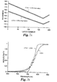
- FIG. 7a An example of a reverse gradient is shown in FIG. 7a.
- This figure shows the combined layer thickness gradient of LTG1 and LTG2.
- the bandedge sharpening gradient, LTG2 consists of 20 layers of alternating high and low index materials, both of which increase in thickness to maintain an f-ratio of 0.5 from the first to last layer pair.
- FIG. 7b Another example of a reverse layer gradient is shown in FIG. 7b.
- This figure shows the short wavelength bandedge for the reflectance band created by layer thickness gradient LTG1 and the effect of adding the reverse gradient LTG2.
- the addition of LTG2 results in an increase to the edge slope.
- the bandedge slope without the addition of LTG 2 is 1.1 percent/nm.
- LTG 2 is added, the slope increases to 1.9 percent/nm.
- the layer thickness profiles are shown in FIG. 7a.
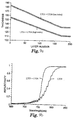
- FIG. 8a An example of a stack design having a reverse gradient with an f-ratio deviation is shown in FIG. 8a.
- This figure shows a film stack design of only one material component with a reverse thickness gradient while the other has a zero gradient in the added band sharpening stack of LTG 3.
- This combination of LTG1 and LTG3 also shows an improvement in bandedge sharpness over the LTG1 case as seen in FIG. 8b below.
- the bandedge slope with LTG 3 added is 7.3 percent/nm.
- This example demonstrates bandedge sharpening for the case of zero gradient stacks LTG4 for both materials.
- the stack design of this example also produces a much sharper bandedge than LTG 1 alone.
- the bandedge slope in this case is 3.6 percent/nm.
- FIG. 9a shows the layer thickness gradient for the combined stacks LTG1 and LTG4.
- LTG4 has a zero thickness gradient for both materials, and maintains a constant ratio of thickness between the high and low index layers.
- Fig. 9b substantial improvement is seen compared to the LTG1 case, with a bandedge slope of 3.6 percent/nm compared to the value of 1.1 percent per. nm for LTG1.
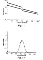
- the layer gradient for the low index layer is linear for the entire stack for LTG1 and LTG5, but the high index component undergoes a gradient reversal in the LTG5 section, as shown in FIG. 10a below.
- the resulting spectra are shown in FIG. 10b, and a substantial improvement is seen vs. the LTG1 case, with the bandedge slope increasing from 1.1 percent/nm to 3.6 percent/nm.
- narrow bandpass transmission filters sometimes referred to as notch filters
- notch filters can be made by using two broad reflection bands which cover most of the appropriate spectrum except for a very narrow band between their adjacent bandedges. If the band pass filter is to be of both narrow band and high transmission, then nearly vertical bandedges are required.
- Typical design techniques of the prior art in which individual layer thicknesses of each layer in the stack is assigned a unique value, may be impractical for polymeric stacks involving hundreds of layers. The edge sharpening techniques described herein are particularly useful in this case.
- One preferred embodiment involves the use of band sharpening stacks having continuously varying gradients.
- the resulting band pass filters have a higher transmission than filters made with linear (constant gradient) layer thickness distributions.
- the following computer modeled examples illustrate this . improvement.
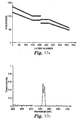
- FIG. 11a A simple band pass filter can be made by introducing a step discontinuity in the layer thickness profile of a broad band reflecting stack, as illustrated in FIG. 11a.
- the bandedge slopes are not high enough to make a narrow band notch filter.
- the bandedges slopes are about 1.2 percent/nm and 1.4 percent/nm for the blue and red edges, respectively.
- the Bandwidth is 54 nm and the peak transmission value is 62 percent.
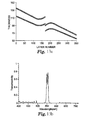
- a notch filter can be made with two graded linear thickness distributions and additional non-graded quarter wave stacks as shown in FIG. 12a.
- the flat (zero gradient) sections are useful for sharpening the respective bandedges of the adjacent reflecting bands. With the additional layers concentrated at the two thickness values on either side of the notch wavelength, a much sharper transmission band can be made.
- the calculated spectrum for the illustrated stack is given in FIG. 12b.
- the steepness of the bandedges of the notch filter spectrum of FIG. 12b will increase with the number of layers included in the band sharpening feature of the stack, as illustrated in FIG. 12b.
- the bandedge slopes are about 9 percent/nm for both the blue and red edges.
- the Bandwidth is 13.8 nm and the peak transmission value is 55.9 percent
- the curved layer thickness profile of FIG. 13a was created to improve upon a deficiency of the stack design and spectrum of FIG. 12a and 12b.
- the side band ripples of the layer thickness profiles of FIG. 12a overlap and limit the transmission of a notch filter. Note that the peak transmission of the notch band in FIG. 12b is only about 50%.
- the bandedge slopes are about 12 percent/nm and 14 percent/nm for the blue and red edges, respectively.
- the Bandwidth is 11 nm and the peak transmission value is 76 percent. Note that, although the bandwidth is narrower than in FIG. 12b, the maximum transmission is significantly higher.
- the number of layers in the band sharpening portion of the stack is 60 on each side of the thickness gap, which is the same number of layers used in the zero gradient sections of the layer distribution of FIG. 12b.
- the curved profile can follow any number of functional forms.
- the main purpose of the form is to break the exact repetition of thickness present in a quarter wave stack with layers tuned to only a single wavelength.
- the particular function used here was an additive function of a linear profile (the same as used on the remainder of the reflectance band) and a sinusoidal function to curve the profile with the appropriate negative or positive second derivative.
- An important feature is that the second derivative of the layer thickness profile is positive for the red bandedge of a reflectance stack and negative for the blue bandedge of a reflectance stack. Note that the opposite sign is required if one refers to the red and blue bandedges of a notch band.
- Other embodiments of the same principle include layer profiles that have multiple points with a zero value of the first derivative. In all cases here, the derivatives refer to those of a best fit curve fitted through the actual layer thickness profile which can contain small statistical errors of less than 10% one sigma standard deviation in layer thickness values.
- the band sharpening profiles that are added to the layer thickness distribution can have significant effects on the slope of the bandedges, for one or both edges of a reflectance band, and for the edges of a pass band.
- Sharp bandedges and high extinction are desirable in obtaining color filters having saturated colors ofhigh purity.
- the slopes of the bandedges are at least about 1 percent per nm, more preferably greater than about 2 percent per nm, and even more preferably greater than about 4 percent per nm.
- the same slopes are preferred for bandpass filters having a bandwidth greater than or about 50 nm.
- the edges are preferably greater than about 2 percent per nm, more preferably greater than about 5 percent per nm, and even more preferably, greater than about 10 percent per nm.
- the polymeric layers of an optical repeating unit in accordance with the present invention can be isotropic or anisotropic.
- An isotropic polymeric layer is a layer wherein the index of refraction of the polymeric layer is the same independent of the direction in the layer, whereas in case of an anisotropic polymeric layer, the index of refraction will differ along at least two different directions.
- the latter type of polymeric layer is also called a birefringent layer.
- an anisotropic polymeric layer an orthogonal set of axes x, y and z is used as set out above in the definition section.
- an anisotropic polymeric layer will have at least two of the indices of refraction n x , n y and n z different from each other.
- optical repeating units R 1 , R 2 and/or R 3 consists of two alternating isotropic polymeric layers that have an index of refraction differing from each other, preferably by at least about 0.05 and more preferably by at least about 0.1. More preferably, however, at least one of the two alternating polymeric layers is a birefringent layer wherein at least one of the in-plane indices n x and n y differs by at least 0.05 from the corresponding in-plane index of refraction of the other layer.
- the index of refraction along the transverse axes (n z ) of both layers is substantially matched, i.e., the difference of the index of refraction along the z-axes between both layers is preferably less than about 0.05.
- Optical repeating units of this type are particularly suitable for reflecting light in the visible region of the spectrum, but may also be used for reflecting light in the infrared region of the spectrum. Optical repeating units and multilayer films having this feature have been described in detail in WO 96/19347 and WO 95/17303.
- the transverse index of the polymer layer having the highest in-plane index is lower than the in-plane indices of the other polymer. This feature is also described in the above-cited references.
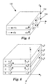
- FIGS. 4a and 4b illustrate these embodiments and show a multilayer film 10 comprising an optical repeating unit consisting of two alternating polymeric layers 12 and 14.
- at least one of the materials has the property of stress induced birefringence, such that the index of refraction (n) of the material is affected by the stretching process.
- FIG. 4a shows an exemplary multilayer film before the stretching process in which both materials have the same index of refraction.
- Light ray 13 experiences relatively little change in index of refraction and passes through the film.
- FIG. 4b the same film has been stretched, thus increasing the index of refraction of material 12 in the stretch direction (or directions). The difference in refractive index at each boundary between layers will cause part of ray 15 to be reflected.
- the multilayer film can thus be made useful as reflective polarizers or mirrors. If stretched biaxially, the sheet can be stretched asymmetrically along orthogonal in-plane axes or symmetrically along orthogonal in-plane axes to obtain desired polarizing and reflecting properties.
- multilayer stacks comprising two alternating polymeric layers
- US-A-5,882,774 The optical properties and design considerations of multilayer stacks comprising two alternating polymeric layers is described most completely in copending and commonly assigned US-A-5,882,774.
- that application describes the construction of multilayer films (mirrors and polarizers) for which the Brewster angle (the angle at which reflectance goes to zero) is very large or is nonexistent for the polymer layer interfaces.
- This feature allows for the construction of mirrors and polarizers whose reflectivity for p-polarized light decreases slowly with angle of incidence, is independent of angle of incidence, or increases with angle of incidence away from normality.
- multilayer films having high reflectivity for both s- and p-polarized light over a wide bandwidth, and over a wide range of angles, can be achieved.
- FIG. 5 shows an optical repeating unit consisting of two polymeric layers, and indicates the three-dimensional indices of refraction for each layer.
- the indices of refraction are n1x, n1y, and n1z for layer 102, and n2x, n2y, and n2z for layer 104, respectively.
- the relationships between the indices of refraction in each film layer to each other and to those of the other layers in the film stack determine the reflectance behavior of the multilayer stack at any angle of incidence, from any azimuthal direction.
- an optical repeating unit of a multilayer film in accordance with the present invention comprises polymeric layers A, B and C having different indices of refraction.
- Such type of repeating unit is particularly suitable for designing an infrared reflective multilayer film.
- an infrared reflective film can be designed for which at least two successive higher order reflections are suppressed, thus allowing the design of an infrared reflective film that is substantially transparent in the visible.
- a multilayer film of this type is described in detail in, e.g., U.S. Patent No. 5,103,337.
- multiple alternating substantially transparent polymeric layers A, B and C having different indices of refraction n i are arranged in the order ABC. Additionally, the refractive index of polymeric layer B is intermediate the respective refractive indices of the polymeric layers A and C.
- the optical thickness ratio f a of first material A is 1/3
- the optical thickness ratio f b of second material B is 1/6
- the optical thickness ratio f of third material C is 1/3
- the index of refraction of polymeric layer B equals the square root of the product of the index of refraction of polymeric layers A and C.
- the above multilayer film having an optical repeating unit comprising polymeric layers A, B and C arranged in an ABCB order can be designed using an anisotropic layer for at least one of polymeric layers A, B and C.
- a multilayer film that reflects light in the infrared region of the spectrum while transmitting light in the visible region of the spectrum may comprise an optical repeating unit comprising polymeric layers A, B and C arranged in an ABCB order, the polymeric layer A having refractive indices n x a and n y a along in-plane axes x and y, respectively, the polymeric layer B having refractive indices n x b and n y b along in-plane axes x and y, respectively, the polymeric layer C having refractive indices n x c and n y c along in-plane axes x and y, respectively, polymeric layers A, B and C having a refractive index n z a , n z b and n z c , respectively, along a transverse axis z perpendicular to the in-plane axes,
- the optical repeating unit By designing the optical repeating unit such that at least one of the differences n z a -n z b and n z b -n z c is less than 0 and preferably less than -0.05, or such that both said differences are substantially 0, and while setting the index relationship along the in-plane axis between the layers as set out above, at least second and third higher order reflections can be suppressed without a substantial decrease of the infrared reflection with angle of incidence of the infrared light.
- the polymeric layers A, B and C of the optical repeating unit preferably form an ABCB optical repeating unit.
- a schematic drawing of such a repeating unit is shown in FIG. 6.
- the difference of the index of refraction between layers A and B along the z-axis (n z a -n z b ) and/or the difference of the index of refraction between layers B and C along the z-axis (n z b -n z c ) is preferably negative, i.e., has a value less than 0, more preferably less or equal to - 0.05, and most preferably less than or equal to -0.1.
- the optical repeating unit such that one of the differences is less than 0, more preferably less than or equal to -0.05, and the other difference is either equal to 0 or less than 0. Most preferably, both difference are less than 0.
- one of the differences in refraction index between layers A and B across the z-axis is of opposite in sign to the difference of the refraction index between layers B and C across the z-axis.
- the difference that is less than 0 has the largest absolute value or that the absolute value of both differences is substantially equal.
- the optical thickness ratios along the particular in-plane axis that has the index of refraction for polymeric layer B intermediate that of polymeric layer A and polymeric layer C at least two higher order reflections for infrared light having its plane of polarization parallel to that particular in-plane axis can be suppressed. It is, however, preferred that the index of refraction for polymeric layer B is intermediate that of polymeric layers A and C along both in-plane axes, and by adjusting the optical thickness ratios along both in-plane axes, an infrared reflective mirror can be obtained for which at least two successive higher order reflections are suppressed. Such an infrared reflective mirror will be substantially clear in the visible region and will be free of color.
- Such an embodiment is capable of suppressing second, third and fourth order reflections.
- An infrared reflective multilayer film designed according to this embodiment can be used to reflect infrared light up to about 2000nm without introducing reflections in the visible part of the spectrum.
- an optical repeating unit comprising polymeric layers A, B and C has, along an in-plane axis, refractive indices of polymers A, B and C different by at least 0.05.
- n x a , n x b and n x c differ from each other by at least 0.05 and/or that n y a , n y b and n y c differ from each other by at least 0.05.
- multilayer films comprising optical repeating units of different design can be used in combination for forming a reflective film body in accordance with the present invention.
- a multilayer film comprising an optical repeating unit consisting of only two polymeric layers can be combined with a multilayer film comprising an optical repeating unit comprising polymeric layers A, B and C arranged in an ABC order in particular in an ABCB pattern.
- the desired refractive index relationships can be achieved in a variety of ways, including stretching during or after film formation (e.g. , in the case of organic polymers), extruding (e.g. , in the case of liquid crystalline materials), or coating.
- the two materials have similar rheological properties (e.g. , melt viscosities) so that they can be co-extruded.
- crystalline, semi-crystalline, or liquid crystalline material or amorphous polymer.
- crystalline or semi-crystalline polymers refer to those polymers that are not amorphous and includes any of those materials commonly referred to as crystalline, partially crystalline, semi-crystalline, etc.
- suitable materials for usew in the present invention include polyethylene naphthalate (PEN) and isomers thereof (e.g. , 2,6-, 1,4-, 1,5-, 2,7-, and 2,3-PEN), polyalkylene terephthalates (e.g. , polyethylene terephthalate, polybutylene terephthalate, and poly-1,4-cyclohexanedimethylene terephthalate), polyimides (e.g. , polyacrylic imides), polyetherimides, atactic polystyrene, polycarbonates, polymethacrylates ( e.g.
- PEN polyethylene naphthalate
- isomers thereof e.g. , 2,6-, 1,4-, 1,5-, 2,7-, and 2,3-PEN
- polyalkylene terephthalates e.g. , polyethylene terephthalate, polybutylene terephthalate, and poly-1,4-cyclohexanedimethylene terephthalate
- polystyrene sPS
- syndiotactic polystyrene sPS
- syndiotactic poly-alpha-methyl styrene syndiotactic polydichlorostyrene
- copolymers and blends of any of these polystyrenes cellulose derivatives ( e.g.
- polyalkylene polymers e.g. , polyethylene, polypropylene, polybutylene, polyisobutylene, and poly(4-methyl)pentene
- fluorinated polymers e.g. , perfluoroalkoxy resins, polytetrafluoroethylene, fluorinated ethylene-propylene copolymers, polyvinylidene fluoride, and polychlorotrifluoroethylene
- chlorinated polymers e.g.
- polyvinylidene chloride and polyvinylchloride polysulfones, polyethersulfones, polyacrylonitrile, polyamides, silicone resins, epoxy resins, polyvinylacetate, polyether-amides, ionomeric resins, elastomers ( e.g. , polybutadiene, polyisoprene, and neoprene), and polyurethanes.
- copolymers e.g. , copolymers of PEN ( e.g.
- cyclohexane dicarboxylic acid e.g., cyclohexane dicarboxylic acid), copolymers of polyalkylene terephthalates (e.g. , copolymers of terephthalic acid, or esters thereof, with (a) naphthalene dicarboxylic acid, or esters thereof; (b) isophthalic acid, or esters thereof; (c) phthalic acid, or esters thereof; (d) alkane glycols; (e) cycloalkane glycols ( e.g. , cyclohexane dimethane diol); (f) alkane dicarboxylic acids; and/or (g) cycloalkane dicarboxylic acids (e.g.
- each individual layer may include blends of two or more of the above-described polymers or copolymers (e.g. , blends of SPS and atactic polystyrene).
- Particularly preferred birefringent polymeric layers for use in the present invention include layers containing a crystalline or semi-crystalline polyethylenenaphthalate (PEN), inclusive of its isomers (e.g. 2,6-; 1,4-; 1,5-; 2,7; and 2,3-PEN).
- PEN crystalline or semi-crystalline polyethylenenaphthalate
- a particularly preferred isotropic polymeric layer for use in connection with this invention is a layer containing a polymethylmethacrylate, and in particular, polymethylmethacrylate itself.
- each of the polymeric layers may be composed of blends of two or more polymeric materials to obtain desired properties for a specific layer.
- the films and other optical devices made in accordance with the invention may also include one or more anti-reflective layers or coatings, such as, for example, conventional vacuum coated dielectric metal oxide or metal/metal oxide optical films, silica sol gel coatings, and coated or coextruded antireflective layers such as those derived from low index fluoropolymers such as THV, an extrudable fluoropolymer available from 3M Company (St. Paul, MN).
- Such layers or coatings which may or may not be polarization sensitive, serve to increase transmission and to reduce reflective glare, and may be imparted to the films and optical devices of the present invention through appropriate surface treatment, such as coating or sputter etching.
- Both visible and near IR dyes and pigments are contemplated for use in the films and other optical bodies of the present invention, and include, for example, optical brighteners such as dyes that absorb in the UV and fluoresce in the visible region of the color spectrum.
- optical brighteners such as dyes that absorb in the UV and fluoresce in the visible region of the color spectrum.
- Other additional layers that may be added to alter the appearance of the optical film include, for example, opacifying (black) layers, diffusing layers, holographic images or holographic diffusers, and metal layers. Each of these may be applied directly to one or both surfaces of the optical film, or may be a component of a second film or foil construction that is laminated to the optical film. Alternately, some components such as opacifying or diffusing agents, or colored pigments, may be included in an adhesive layer which is used to laminate the optical film to another surface.
- the polymers have compatible rheologies for coextrusion. That is, as a preferred method of forming the reflective film bodies is the use of coextrusion techniques, the melt viscosities of the polymers are preferably reasonably matched to prevent layer instability or non-uniformity.
- the polymers used also preferably have sufficient interfacial adhesion so that the films will not delaminate.
- the multilayer reflective film bodies of the present invention can be readily manufactured in a cost effective way, and they can be formed and shaped into a variety of useful configurations after coextrusion.
- Multilayer reflective film bodies in accordance with the present invention are most advantageously prepared by employing a multilayered coextrusion device such as those described in U.S. Patent Nos. 3,773,882 and 3,884,606.
- Such devices provide a method for preparing multilayered, simultaneously extruded thermoplastic materials, each of which are of a substantially uniform layer thickness.
- a series of layer multiplying means as are described in U.S. Patent. No. 3,759,647 may be employed.
- the feedblock of the coextrusion device receives streams of the diverse thermoplastic polymeric materials from a source such as a heat plastifying extruder.
- the streams of resinous materials are passed to a mechanical manipulating section within the feedblock. This section serves to rearrange the original streams into a multilayered stream having the number of layers desired in the final body.
- this multilayered stream may be subsequently passed through a series of layer multiplying means in order to further increase the number of layers in the final body.
- the multilayered stream is then passed into an extrusion die which is so constructed and arranged that stream-lined flow is maintained therein.
- an extrusion device is described in U.S. Patent No. 3,557,265.
- the resultant product is extruded to form a multilayered body in which each layer is generally parallel to the major surface of adjacent layers.
- the configuration of the extrusion die can vary and can be such as to reduce the thickness and dimensions of each of the layers.
- the precise degree of reduction in thickness of the layers delivered from the mechanical orienting section, the configuration of the die, and the amount of mechanical working of the body after extrusion are all factors which affect the thickness of the individual layers in the final body.
- the number of layers in the reflective film body can be selected to achieve the desired optical properties using the minimum number of layers for reasons of film thickness, flexibility and economy.
- the number of layers is preferably less than about 10,000, more preferably less than about 5,000, and (even more preferably) less than about 2,000.
- the desired relationship between refractive indices of polymeric layers as desired in this invention can be achieved by selection of appropriate processing conditions used to prepare the reflective film body.
- the multilayer films are generally prepared by co-extruding the individual polymers to form a multilayer film (e.g., as set out above) and then orienting the reflective film body by stretching at a selected temperature, optionally followed by heat-setting at a selected temperature. Alternatively, the extrusion and orientation steps may be performed simultaneously.
- the desired extent of birefringence (negative or positive) is set in those polymeric layers that comprise a polymer that can exhibit birefringence.
- Negative birefringence is obtained with polymers that show a negative optical stress coefficient, i.e., polymers for which the in-plane indices will decrease with orientation, whereas positive birefringence is obtained with polymers having a positive optical stress coefficient.
- This terminology in the art of film orientation conflicts somewhat with the standard optical definition of positive and negative birefringence.
- a uniaxially positive birefringent film or layer is one in which the z-index of refraction is higher than the in-plane index.
- a biaxially stretched polymer film such as PET will have high in-plane indices, e.g., 1.65, and a low out-of-plane or z-axis index of 1.50.
- a material such as PET is said to be positively birefringent because the index increases in the stretch direction, but in the art of optics, the same material, after biaxially stretching to film, is said to have uniaxial negative birefringence because the z-index is lower than the in-plane indices which are substantially equal.
- the term "positive birefringence” for a material as used herein will be that of the polymer film art, and will mean that the index of refraction increases in the stretch direction.
- the term “negative birefringence” for a material will mean that the index of refraction of a film decreases in the direction of stretch.
- the terms ''uniaxially positive” or “uniaxially negative”, when used in reference to a birefringent layer, will be taken to have the meaning in the optics sense.
- the reflective film body is stretched substantially in one direction (uniaxial orientation), while in the case of mirrors the film can be stretched substantially in two directions (biaxial orientation).
- the stretching may be asymmetric to introduce specially desired features, but is preferably symmetric.
- the reflective film body may be allowed to dimensionally relax in the cross-stretch direction from the natural reduction in cross-stretch (equal to the square root of the stretch ratio) or may be constrained (i.e., no substantial change in cross-stretch dimensions).
- the reflective film body may be stretched in the machine direction, as with a length orienter, and/or in width using a tenter.
- the pre-stretch temperature, stretch temperature, stretch rate, stretch ratio, heat set temperature, heat set time, heat set relaxation, and cross-stretch relaxation are selected to yield a multilayer device having the desired refractive index relationship.
- These variables are inter-dependent; thus, for example, a relatively low stretch rate could be used if coupled with, e.g., a relatively low stretch temperature. It will be apparent to one skilled in the art how to select the appropriate combination of these variables to achieve the desired multilayer device.
- a stretch ratio in the range from about 1:2 to about 1:10 (more preferably about 1:3 to about 1:7) in the stretch direction and from about 1:0.2 to about 1:10 (more preferably from about 1:0.2 to about 1:7) orthogonal to the stretch direction is preferred.
- Orientation of the extruded film can be accomplished by stretching individual sheets of the material in heated air.
- stretching may be accomplished on a continuous basis in a standard length orienter, tenter oven, or both.
- economies of scale and line speeds of standard polymer film production may be achieved, thereby achieving manufacturing costs that are substantially lower than costs associated with commercially available absorptive polarizers.
- Two or more multilayer films may also be laminated together to obtain a reflective film body in accordance with the present invention.
- Amorphous copolyesters such as those available under the trade designation VITEL 3000 and 3300 from the Goodyear Tire and Rubber Co. of Akron, Ohio, are useful as laminating materials.
- the choice of laminating material is broad, with adhesion to the multilayer films, optical clarity and exclusion of air being the primary guiding principles.
- inorganic or organic adjuvants such as an antioxidant, extrusion aid, heat stabilizer, ultraviolet ray absorber, nucleator, surface projection forming agent, and the like in normal quantities so long as the addition does not substantially interfere with the performance of the present invention.
Landscapes
- Physics & Mathematics (AREA)
- General Physics & Mathematics (AREA)
- Optics & Photonics (AREA)
- Engineering & Computer Science (AREA)
- Health & Medical Sciences (AREA)
- Manufacturing & Machinery (AREA)
- Ophthalmology & Optometry (AREA)
- Mechanical Engineering (AREA)
- Optical Filters (AREA)
- Laminated Bodies (AREA)
- Optical Elements Other Than Lenses (AREA)
Applications Claiming Priority (3)
| Application Number | Priority Date | Filing Date | Title |
|---|---|---|---|
| US09/006,085 US6157490A (en) | 1998-01-13 | 1998-01-13 | Optical film with sharpened bandedge |
| US6085 | 1998-01-13 | ||
| PCT/US1999/000452 WO1999036809A1 (en) | 1998-01-13 | 1999-01-08 | Optical film with sharpened bandedge |
Publications (2)
| Publication Number | Publication Date |
|---|---|
| EP1047963A1 EP1047963A1 (en) | 2000-11-02 |
| EP1047963B1 true EP1047963B1 (en) | 2003-11-26 |
Family
ID=21719234
Family Applications (1)
| Application Number | Title | Priority Date | Filing Date |
|---|---|---|---|
| EP99901387A Expired - Lifetime EP1047963B1 (en) | 1998-01-13 | 1999-01-08 | Optical film with sharpened bandedge |
Country Status (9)
| Country | Link |
|---|---|
| US (2) | US6157490A (enExample) |
| EP (1) | EP1047963B1 (enExample) |
| JP (1) | JP4399113B2 (enExample) |
| KR (1) | KR100582973B1 (enExample) |
| CN (1) | CN1141604C (enExample) |
| AU (1) | AU2109699A (enExample) |
| BR (1) | BR9906907A (enExample) |
| DE (1) | DE69913102T2 (enExample) |
| WO (1) | WO1999036809A1 (enExample) |
Cited By (1)
| Publication number | Priority date | Publication date | Assignee | Title |
|---|---|---|---|---|
| EP3650893B1 (en) * | 2017-07-07 | 2025-11-05 | Toyobo Co., Ltd. | Multilayer film stack |
Families Citing this family (209)
| Publication number | Priority date | Publication date | Assignee | Title |
|---|---|---|---|---|
| US6498683B2 (en) | 1999-11-22 | 2002-12-24 | 3M Innovative Properties Company | Multilayer optical bodies |
| US5882774A (en) | 1993-12-21 | 1999-03-16 | Minnesota Mining And Manufacturing Company | Optical film |
| EP0735952B1 (en) | 1993-12-21 | 2000-03-22 | Minnesota Mining And Manufacturing Company | Multilayered optical film |
| WO1997001726A1 (en) | 1995-06-26 | 1997-01-16 | Minnesota Mining And Manufacturing Company | Backlight system with multilayer optical film reflector |
| US6080467A (en) * | 1995-06-26 | 2000-06-27 | 3M Innovative Properties Company | High efficiency optical devices |
| US6486997B1 (en) | 1997-10-28 | 2002-11-26 | 3M Innovative Properties Company | Reflective LCD projection system using wide-angle Cartesian polarizing beam splitter |
| US7023602B2 (en) | 1999-05-17 | 2006-04-04 | 3M Innovative Properties Company | Reflective LCD projection system using wide-angle Cartesian polarizing beam splitter and color separation and recombination prisms |
| US6926952B1 (en) * | 1998-01-13 | 2005-08-09 | 3M Innovative Properties Company | Anti-reflective polymer constructions and method for producing same |
| US6788463B2 (en) | 1998-01-13 | 2004-09-07 | 3M Innovative Properties Company | Post-formable multilayer optical films and methods of forming |
| US6808658B2 (en) | 1998-01-13 | 2004-10-26 | 3M Innovative Properties Company | Method for making texture multilayer optical films |
| US6157490A (en) * | 1998-01-13 | 2000-12-05 | 3M Innovative Properties Company | Optical film with sharpened bandedge |
| US6531230B1 (en) | 1998-01-13 | 2003-03-11 | 3M Innovative Properties Company | Color shifting film |
| US6515785B1 (en) * | 1999-04-22 | 2003-02-04 | 3M Innovative Properties Company | Optical devices using reflecting polarizing materials |
| CN1400939A (zh) * | 2000-02-11 | 2003-03-05 | 丹格乐斯技术有限公司 | 含有二氧化铈的抗反射防紫外线多层涂层 |
| US6419483B1 (en) | 2000-03-01 | 2002-07-16 | 3M Innovative Properties Company | Method and apparatus for curling light-curable dental materials |
| US6797396B1 (en) | 2000-06-09 | 2004-09-28 | 3M Innovative Properties Company | Wrinkle resistant infrared reflecting film and non-planar laminate articles made therefrom |
| AU7024801A (en) | 2000-06-28 | 2002-01-08 | 3M Innovative Properties Co | Enhanced sample processing devices, systems and methods |
| ATE374953T1 (de) | 2000-08-21 | 2007-10-15 | 3M Innovative Properties Co | Reflektierende optische filter mit verlustoptimierung |
| US6767609B2 (en) | 2000-09-15 | 2004-07-27 | 3M Innovative Properties Company | Perforated film constructions for backlit signs |
| WO2002061469A2 (en) * | 2001-01-15 | 2002-08-08 | 3M Innovative Properties Company | Multilayer infrared reflecting film with high and smooth transmission in visible wavelength region and laminate articles made therefrom |
| US7052762B2 (en) | 2001-05-24 | 2006-05-30 | 3M Innovative Properties Company | Low Tg multilayer optical films |
| US6521329B2 (en) * | 2001-06-18 | 2003-02-18 | Eastman Kodak Company | Radiographic phosphor panel having reflective polymeric supports |
| US6611378B1 (en) | 2001-12-20 | 2003-08-26 | Semrock, Inc. | Thin-film interference filter with quarter-wavelength unit sub-layers arranged in a generalized pattern |
| US7189447B2 (en) | 2002-01-04 | 2007-03-13 | 3M Innovative Properties Company | Laminates |
| US6652996B2 (en) * | 2002-01-31 | 2003-11-25 | Eastman Kodak Company | Radiographic phosphor panel having improved speed and sharpness |
| US6888143B2 (en) | 2002-03-09 | 2005-05-03 | Kimberly-Clark Worldwide, Inc. | Apparatus and method for inspecting pre-fastened articles |
| US6885451B2 (en) | 2002-03-09 | 2005-04-26 | Kimberly-Clark Worldwide, Inc. | Infrared detection of composite article components |
| US6927857B2 (en) | 2002-03-09 | 2005-08-09 | Kimberly-Clark Worldwide, Inc. | Process for the detection of marked components of a composite article using infrared blockers |
| US6900450B2 (en) | 2002-03-09 | 2005-05-31 | Kimberly-Clark Worldwide, Inc. | Method and apparatus for inferring item position based on multiple data |
| US6919965B2 (en) | 2002-03-09 | 2005-07-19 | Kimberly-Clark Worldwide, Inc. | Apparatus and method for making and inspecting pre-fastened articles |
| US6991695B2 (en) * | 2002-05-21 | 2006-01-31 | 3M Innovative Properties Company | Method for subdividing multilayer optical film cleanly and rapidly |
| US7095009B2 (en) * | 2002-05-21 | 2006-08-22 | 3M Innovative Properties Company | Photopic detector system and filter therefor |
| US7396493B2 (en) * | 2002-05-21 | 2008-07-08 | 3M Innovative Properties Company | Multilayer optical film with melt zone to control delamination |
| US20050041292A1 (en) * | 2002-05-21 | 2005-02-24 | Wheatley John A. | Visible wavelength detector systems and filters therefor |
| US20040057142A1 (en) * | 2002-07-10 | 2004-03-25 | Denglas Technologies, L.L.C. | Method of making stress-resistant anti-reflection multilayer coatings containing cerium oxide |
| US7123765B2 (en) | 2002-07-31 | 2006-10-17 | Kimberly-Clark Worldwide, Inc. | Apparatus and method for inspecting articles |
| US7215473B2 (en) * | 2002-08-17 | 2007-05-08 | 3M Innovative Properties Company | Enhanced heat mirror films |
| ES2263067T3 (es) | 2002-11-05 | 2006-12-01 | N.V. Bekaert S.A. | Estructura en capas de reflexion infrarroja. |
| US7064897B2 (en) * | 2002-12-31 | 2006-06-20 | 3M Innovative Properties Company | Optical polarizing films with designed color shifts |
| DE10319005A1 (de) * | 2003-04-25 | 2004-11-25 | Carl Zeiss Smt Ag | Reflektives optisches Element, optisches System und EUV-Lithographievorrichtung |
| US20040219338A1 (en) * | 2003-05-01 | 2004-11-04 | Hebrink Timothy J. | Materials, configurations, and methods for reducing warpage in optical films |
| US20040227994A1 (en) * | 2003-05-16 | 2004-11-18 | Jiaying Ma | Polarizing beam splitter and projection systems using the polarizing beam splitter |
| US6808394B1 (en) | 2003-06-23 | 2004-10-26 | American Polarizers, Inc. | System for demonstrating effects of polarized lens |
| WO2005017580A1 (en) * | 2003-07-16 | 2005-02-24 | 3M Innovative Properties Company | Laminates and methods of making same |
| US6859323B1 (en) | 2003-12-11 | 2005-02-22 | Optical Coating Laboratory, Inc. | Dichroic neutral density optical filter |
| US7234816B2 (en) * | 2004-02-03 | 2007-06-26 | 3M Innovative Properties Company | Polarizing beam splitter assembly adhesive |
| DE102004021494B4 (de) * | 2004-04-30 | 2006-04-06 | Man Roland Druckmaschinen Ag | Vorrichtung zum Auf- und Abziehen einer Hülse |
| US7201497B2 (en) * | 2004-07-15 | 2007-04-10 | Lumination, Llc | Led lighting system with reflective board |
| JP4578900B2 (ja) * | 2004-09-07 | 2010-11-10 | 富士フイルム株式会社 | 光学フイルム、偏光板及び液晶表示装置 |
| US7329465B2 (en) | 2004-10-29 | 2008-02-12 | 3M Innovative Properties Company | Optical films incorporating cyclic olefin copolymers |
| JP5069570B2 (ja) * | 2005-02-16 | 2012-11-07 | コーニンクレッカ フィリップス エレクトロニクス エヌ ヴィ | 特定のプレチルト角を持つ配列ポリマーを含んだ発光体 |
| US7315418B2 (en) * | 2005-03-31 | 2008-01-01 | 3M Innovative Properties Company | Polarizing beam splitter assembly having reduced stress |
| US20060221447A1 (en) * | 2005-03-31 | 2006-10-05 | 3M Innovative Properties Company | Stabilized polarizing beam splitter assembly |
| US7474286B2 (en) | 2005-04-01 | 2009-01-06 | Spudnik, Inc. | Laser displays using UV-excitable phosphors emitting visible colored light |
| US7791561B2 (en) | 2005-04-01 | 2010-09-07 | Prysm, Inc. | Display systems having screens with optical fluorescent materials |
| US7733310B2 (en) | 2005-04-01 | 2010-06-08 | Prysm, Inc. | Display screens having optical fluorescent materials |
| US20060227421A1 (en) | 2005-04-06 | 2006-10-12 | Stover Carl A | Optical bodies including strippable boundary layers |
| WO2006107969A1 (en) | 2005-04-06 | 2006-10-12 | 3M Innovative Properties Company | Optical bodies including rough strippable boundary layers and asymmetric surface structures |
| US9709700B2 (en) | 2005-04-06 | 2017-07-18 | 3M Innovative Properties Company | Optical bodies including rough strippable boundary layers |
| US7385763B2 (en) * | 2005-04-18 | 2008-06-10 | 3M Innovative Properties Company | Thick film multilayer reflector with tailored layer thickness profile |
| US8000005B2 (en) | 2006-03-31 | 2011-08-16 | Prysm, Inc. | Multilayered fluorescent screens for scanning beam display systems |
| US8089425B2 (en) | 2006-03-03 | 2012-01-03 | Prysm, Inc. | Optical designs for scanning beam display systems using fluorescent screens |
| US7994702B2 (en) | 2005-04-27 | 2011-08-09 | Prysm, Inc. | Scanning beams displays based on light-emitting screens having phosphors |
| US20070097509A1 (en) * | 2005-10-31 | 2007-05-03 | Nevitt Timothy J | Optical elements for high contrast applications |
| US8451195B2 (en) | 2006-02-15 | 2013-05-28 | Prysm, Inc. | Servo-assisted scanning beam display systems using fluorescent screens |
| US7884816B2 (en) | 2006-02-15 | 2011-02-08 | Prysm, Inc. | Correcting pyramidal error of polygon scanner in scanning beam display systems |
| US20070242197A1 (en) * | 2006-04-12 | 2007-10-18 | 3M Innovative Properties Company | Transflective LC Display Having Backlight With Spatial Color Separation |
| US20070247573A1 (en) * | 2006-04-19 | 2007-10-25 | 3M Innovative Properties Company | Transflective LC Display Having Narrow Band Backlight and Spectrally Notched Transflector |
| WO2008011464A1 (en) * | 2006-07-18 | 2008-01-24 | 3M Innovative Properties Company | Calendering process for making an optical film |
| CN101511641B (zh) | 2006-08-01 | 2015-09-23 | 3M创新有限公司 | 照明装置 |
| US7773302B2 (en) * | 2006-09-01 | 2010-08-10 | Semrock, Inc. | Low cost filter for fluorescence systems |
| US8525402B2 (en) | 2006-09-11 | 2013-09-03 | 3M Innovative Properties Company | Illumination devices and methods for making the same |
| US8581393B2 (en) | 2006-09-21 | 2013-11-12 | 3M Innovative Properties Company | Thermally conductive LED assembly |
| US20080083998A1 (en) * | 2006-10-06 | 2008-04-10 | 3M Innovative Properties Company | Multiple draw gap length orientation process |
| US20080085383A1 (en) * | 2006-10-06 | 2008-04-10 | 3M Innovative Properties Company | Processes for improved optical films |
| KR100809849B1 (ko) * | 2006-11-10 | 2008-03-04 | 엘지.필립스 엘시디 주식회사 | 광학 필름 및 이의 제조 방법, 그리고 액정 표시 장치 |
| US8013506B2 (en) | 2006-12-12 | 2011-09-06 | Prysm, Inc. | Organic compounds for adjusting phosphor chromaticity |
| CN101573643B (zh) * | 2006-12-27 | 2011-03-09 | 帝人株式会社 | 偏振元件和液晶显示装置 |
| WO2008116123A1 (en) * | 2007-03-20 | 2008-09-25 | Spudnik, Inc. | Delivering and displaying advertisement or other application data to display systems |
| US8169454B1 (en) | 2007-04-06 | 2012-05-01 | Prysm, Inc. | Patterning a surface using pre-objective and post-objective raster scanning systems |
| US7697183B2 (en) | 2007-04-06 | 2010-04-13 | Prysm, Inc. | Post-objective scanning beam systems |
| US20080271739A1 (en) | 2007-05-03 | 2008-11-06 | 3M Innovative Properties Company | Maintenance-free respirator that has concave portions on opposing sides of mask top section |
| US9770611B2 (en) | 2007-05-03 | 2017-09-26 | 3M Innovative Properties Company | Maintenance-free anti-fog respirator |
| RU2442197C2 (ru) | 2007-05-17 | 2012-02-10 | Призм, Инк. | Многослойные экраны со светоизлучающими полосками для систем отображения со сканирующим лучом |
| TWI467283B (zh) | 2007-05-20 | 2015-01-01 | 3M Innovative Properties Co | 具有半反射鏡組件之再循環背光 |
| US8523419B2 (en) | 2007-05-20 | 2013-09-03 | 3M Innovative Properties Company | Thin hollow backlights with beneficial design characteristics |
| TWI439641B (zh) | 2007-05-20 | 2014-06-01 | 3M Innovative Properties Co | 用於側面發光型背光之準直光注入器 |
| EP2535766A3 (en) | 2007-05-20 | 2013-05-01 | 3M Innovative Properties Company | Asymmetric reflective film and backlight having a hollow cavity, which recycles the light |
| US7878657B2 (en) | 2007-06-27 | 2011-02-01 | Prysm, Inc. | Servo feedback control based on invisible scanning servo beam in scanning beam display systems with light-emitting screens |
| US8556430B2 (en) | 2007-06-27 | 2013-10-15 | Prysm, Inc. | Servo feedback control based on designated scanning servo beam in scanning beam display systems with light-emitting screens |
| CN101452088B (zh) * | 2007-12-07 | 2011-07-27 | 财团法人工业技术研究院 | 低或零双折射光学薄膜及其制造方法 |
| CN101939675A (zh) | 2008-02-07 | 2011-01-05 | 3M创新有限公司 | 具有结构化膜的中空背光源 |
| WO2009105450A1 (en) | 2008-02-22 | 2009-08-27 | 3M Innovative Properties Company | Backlights having selected output light flux distributions and display systems using same |
| US9664834B2 (en) * | 2008-03-31 | 2017-05-30 | 3M Innovative Properties Company | Optical film |
| EP2263111B1 (en) | 2008-03-31 | 2019-05-29 | 3M Innovative Properties Company | Low layer count reflective polarizer with optimized gain |
| BRPI0907685A2 (pt) | 2008-04-30 | 2019-02-26 | 3M Innovative Properties Co | sistema de iluminação e acoplador de injeção de luz para o mesmo |
| EP2297607B1 (en) | 2008-06-04 | 2014-04-23 | 3M Innovative Properties Company | Hollow backlight with tilted light source |
| US8130376B2 (en) * | 2008-06-05 | 2012-03-06 | Avalon Instruments Ltd. | Optical devices, spectroscopic systems and methods for detecting scattered light |
| US7869112B2 (en) * | 2008-07-25 | 2011-01-11 | Prysm, Inc. | Beam scanning based on two-dimensional polygon scanner for display and other applications |
| US20110222263A1 (en) * | 2008-11-19 | 2011-09-15 | Weber Michael F | High transmission flux leveling multilayer optical film and related constructions |
| WO2010059566A1 (en) * | 2008-11-19 | 2010-05-27 | 3M Innovative Properties Company | Multilayer optical film with output confinement in both polar and azimuthal directions and related constructions |
| US8662687B2 (en) * | 2008-11-19 | 2014-03-04 | 3M Innovative Properties Company | Brewster angle film for light management in luminaires and other lighting systems |
| WO2010059568A1 (en) * | 2008-11-19 | 2010-05-27 | 3M Innovative Properties Company | Reflective film combinations with output confinement in both polar and azimuthal directions and related constructions |
| KR101689045B1 (ko) | 2008-12-22 | 2016-12-22 | 쓰리엠 이노베이티브 프로퍼티즈 컴파니 | 복수의 복굴절성 층을 구비한 내부 패턴화된 다층 광학 필름 |
| US9523516B2 (en) | 2008-12-30 | 2016-12-20 | 3M Innovative Properties Company | Broadband reflectors, concentrated solar power systems, and methods of using the same |
| IT1392502B1 (it) * | 2008-12-31 | 2012-03-09 | St Microelectronics Srl | Sensore comprendente almeno un fotodiodo a doppia giunzione verticale integrato su substrato semiconduttore e relativo processo di integrazione |
| US20100163759A1 (en) * | 2008-12-31 | 2010-07-01 | Stmicroelectronics S.R.L. | Radiation sensor with photodiodes being integrated on a semiconductor substrate and corresponding integration process |
| EP2460186A1 (en) | 2009-07-31 | 2012-06-06 | Technische Universiteit Eindhoven | Luminescent optical device and solar cell system with such luminescent optical device |
| CN102576114B (zh) | 2009-10-24 | 2016-10-26 | 3M创新有限公司 | 在选定入射平面内具有角度限制的浸入型反射偏振片 |
| US9158155B2 (en) | 2009-10-24 | 2015-10-13 | 3M Innovative Properties Company | Immersed reflective polarizer with high off-axis reflectivity |
| WO2011050254A1 (en) | 2009-10-24 | 2011-04-28 | 3M Innovative Properties Company | Light source and display system incorporating same |
| US9057843B2 (en) | 2009-10-24 | 2015-06-16 | 3M Innovative Properties Company | Immersed asymmetric reflector with reduced color |
| EP3270049A3 (en) | 2009-12-08 | 2018-04-18 | 3M Innovative Properties Co. | Optical constructions incorporating a light guide and low refractive index films |
| EP2339382A1 (en) | 2009-12-22 | 2011-06-29 | 3M Innovative Properties Company | A light guide for a dental light device and a method of making the light guide |
| CN103038680B (zh) | 2010-06-30 | 2015-12-02 | 3M创新有限公司 | 具有空间选择性双折射减小的延迟膜组合 |
| WO2012003213A1 (en) | 2010-06-30 | 2012-01-05 | 3M Innovative Properties Company | Diffuse reflective optical films with spatially selective birefringence reduction |
| CN103038681B (zh) | 2010-06-30 | 2016-09-28 | 3M创新有限公司 | 使用具有空间选择性双折射减小的膜的掩模加工 |
| BR112013004669A2 (pt) | 2010-09-08 | 2016-08-02 | 3M Innovative Properties Co | ''artigo,painel e sistemas de telhado'' |
| WO2012054318A1 (en) | 2010-10-20 | 2012-04-26 | 3M Innovative Properties Company | Wide band semi-specular mirror film incorporating nanovoided polymeric layer |
| KR101740603B1 (ko) * | 2010-12-27 | 2017-05-29 | 에스케이씨 주식회사 | 적외선 차단 다층 필름 |
| WO2012092478A1 (en) | 2010-12-30 | 2012-07-05 | 3M Innovative Properties Company | Laser cutting method and articles produced therewith |
| KR20140005222A (ko) | 2010-12-30 | 2014-01-14 | 쓰리엠 이노베이티브 프로퍼티즈 컴파니 | 금 대향 층을 갖는 지지 부재를 사용하여 레이저 절단하기 위한 장치 및 방법 |
| CN103477147B (zh) | 2011-04-08 | 2015-01-14 | 3M创新有限公司 | 光管道t形提取器 |
| AU2012268349A1 (en) | 2011-06-07 | 2014-01-09 | 3M Innovative Properties Company | System and method for management of a roof |
| WO2013059228A1 (en) | 2011-10-20 | 2013-04-25 | 3M Innovative Properties Company | Apodized broadband partial reflectors having differing optical packets |
| US9322967B2 (en) | 2011-10-20 | 2016-04-26 | 3M Innovative Properties Company | Apodized broadband partial reflectors |
| US9441809B2 (en) | 2011-10-20 | 2016-09-13 | 3M Innovative Properties Company | Illumination systems with sloped transmission spectrum front reflector |
| WO2013096171A1 (en) | 2011-12-22 | 2013-06-27 | 3M Innovative Properties Company | Above-deck roof venting article |
| TWI474079B (zh) * | 2012-03-14 | 2015-02-21 | Extend Optronics Corp | 反射式光學膜及其製作方法、及影像顯示器 |
| TWI580994B (zh) * | 2012-05-15 | 2017-05-01 | Dainippon Printing Co Ltd | A laminated substrate, a laminate, a polarizing plate, a liquid crystal display panel, and an image display device |
| US20130314788A1 (en) * | 2012-05-24 | 2013-11-28 | Extend Optronics Corp. | Reflective optical film and method of manufacturing the same, and image display device |
| KR20140001787A (ko) * | 2012-06-28 | 2014-01-07 | 코오롱인더스트리 주식회사 | 휘도 증강 필름 및 이를 포함하는 백라이트 유닛 |
| US20140065397A1 (en) | 2012-08-28 | 2014-03-06 | 3M Innovative Properties Company | Coextruded polymer film configured for successive irreversible delamination |
| US9228355B2 (en) | 2012-11-01 | 2016-01-05 | 3M Innovative Properties Company | Above-deck roof venting article |
| EP2943824B1 (en) | 2013-01-14 | 2017-11-22 | 3M Innovative Properties Company | Filters to enhance color discrimination for color vision deficient individuals |
| US9279921B2 (en) * | 2013-04-19 | 2016-03-08 | 3M Innovative Properties Company | Multilayer stack with overlapping harmonics for wide visible-infrared coverage |
| USD746974S1 (en) | 2013-07-15 | 2016-01-05 | 3M Innovative Properties Company | Exhalation valve flap |
| CA2917504C (en) | 2013-07-15 | 2022-06-21 | 3M Innovative Properties Company | Respirator having optically active exhalation valve |
| KR102177207B1 (ko) | 2013-07-18 | 2020-11-11 | 삼성디스플레이 주식회사 | 표시장치 |
| US9864120B2 (en) | 2013-09-05 | 2018-01-09 | 3M Innovative Properties Company | Patterned marking of multilayer optical film by thermal conduction |
| SG11201601633UA (en) | 2013-09-06 | 2016-04-28 | 3M Innovative Properties Co | Multilayer reflective polarizer |
| US10146055B2 (en) * | 2013-09-06 | 2018-12-04 | 3M Innovative Properties Company | Head mounted display with eye tracking |
| US20150077873A1 (en) | 2013-09-16 | 2015-03-19 | 3M Innovative Properties Company | Adhesive articles containing light shielding film substrates, method of making thereof and articles therefrom |
| EP3052975B1 (en) * | 2013-09-30 | 2022-02-23 | 3M Innovative Properties Company | Polymeric multilayer optical film |
| KR102258229B1 (ko) | 2013-11-19 | 2021-06-01 | 쓰리엠 이노베이티브 프로퍼티즈 캄파니 | 다층 중합체성 반사기 |
| US9885885B2 (en) | 2013-11-27 | 2018-02-06 | 3M Innovative Properties Company | Blue edge filter optical lens |
| WO2015102961A1 (en) | 2013-12-30 | 2015-07-09 | 3M Innovative Properties Company | Optical film including collimating reflective polarizer |
| US9841598B2 (en) | 2013-12-31 | 2017-12-12 | 3M Innovative Properties Company | Lens with embedded multilayer optical film for near-eye display systems |
| US9739916B2 (en) | 2014-03-20 | 2017-08-22 | 3M Innovative Properties Company | Circadian rhythm optical film |
| CN112904562A (zh) | 2014-04-09 | 2021-06-04 | 3M创新有限公司 | 作为组合器的具有薄膜的近眼显示系统 |
| WO2016025443A1 (en) | 2014-08-13 | 2016-02-18 | 3M Innovative Properties Company | Head-mounted display system and components |
| AU2015355331B2 (en) * | 2014-12-05 | 2018-03-29 | 3M Innovative Properties Company | Vision-protecting filter lens |
| MX2017008747A (es) | 2014-12-30 | 2018-03-15 | 3M Innovative Properties Co | Apilamiento optico que incluye polarizador reflectante y pelicula de compensacion. |
| CN107407758A (zh) | 2015-02-27 | 2017-11-28 | 3M创新有限公司 | 包括准直反射偏振器和结构化层的光学膜 |
| WO2016148141A1 (ja) * | 2015-03-17 | 2016-09-22 | 東レ株式会社 | 積層フィルム、それを用いた液晶ディスプレイ、タッチパネルおよび有機elディスプレイ |
| GB201508114D0 (en) | 2015-05-12 | 2015-06-24 | 3M Innovative Properties Co | Respirator tab |
| EP3317624B1 (en) | 2015-07-05 | 2019-08-07 | The Whollysee Ltd. | Optical identification and characterization system and tags |
| WO2017019450A2 (en) | 2015-07-24 | 2017-02-02 | 3M Innovative Properties Company | Reflective stack with heat spreading layer |
| KR20180059866A (ko) | 2015-10-02 | 2018-06-05 | 쓰리엠 이노베이티브 프로퍼티즈 컴파니 | 광학 필터 |
| JP7519170B2 (ja) | 2015-12-18 | 2024-07-19 | スリーエム イノベイティブ プロパティズ カンパニー | 広帯域可視光反射体 |
| WO2017165280A1 (en) | 2016-03-21 | 2017-09-28 | Hubbell Incorporated | Light fixture with narrow light distribution |
| JP2019523442A (ja) | 2016-07-13 | 2019-08-22 | スリーエム イノベイティブ プロパティズ カンパニー | 光学フィルム |
| US10613264B2 (en) | 2016-09-13 | 2020-04-07 | 3M Innovative Properties Company | Single packet reflective polarizer with thickness profile tailored for low color at oblique angles |
| CN110622048B (zh) | 2017-03-02 | 2023-03-28 | 3M创新有限公司 | 具有低光学厚度敏感性的动态反射彩色膜 |
| WO2018165126A1 (en) | 2017-03-06 | 2018-09-13 | 3M Innovative Properties Company | Vehicle projection assembly |
| CN110869110B (zh) | 2017-07-14 | 2022-11-18 | 3M创新有限公司 | 用于输送多个液体流的适配器 |
| JP7386165B2 (ja) | 2017-10-02 | 2023-11-24 | スリーエム イノベイティブ プロパティズ カンパニー | 色シフトを補正するための部分反射体 |
| EP3693772B1 (en) * | 2017-10-03 | 2024-06-12 | Toray Industries, Inc. | Laminate film |
| JP7541921B2 (ja) | 2017-10-09 | 2024-08-29 | スリーエム イノベイティブ プロパティズ カンパニー | 光学構成要素及び光学システム |
| CN114217373B (zh) | 2017-10-20 | 2025-04-01 | 3M创新有限公司 | 光学膜和偏振分束器 |
| WO2019106597A1 (en) * | 2017-12-01 | 2019-06-06 | 3M Innovative Properties Company | Thin multilayer reflector with uniform left bandedge |
| KR20200115495A (ko) | 2018-01-26 | 2020-10-07 | 쓰리엠 이노베이티브 프로퍼티즈 컴파니 | 결정질 저 굴절률 층을 갖는 다층 반사 편광기 |
| JP7143878B2 (ja) * | 2018-02-22 | 2022-09-29 | 東洋紡株式会社 | 多層積層フィルム |
| US10850595B2 (en) | 2018-03-07 | 2020-12-01 | Magna Electronics Inc. | Vehicular sensing system with attenuation of reflected-refracted light off of precipitation using light polarization |
| JP7438128B2 (ja) | 2018-04-18 | 2024-02-26 | スリーエム イノベイティブ プロパティズ カンパニー | 色補正構成要素を有する有機発光ダイオードディスプレイ及びその作製方法 |
| WO2020016703A2 (en) | 2018-07-17 | 2020-01-23 | 3M Innovative Properties Company | Optical film including infrared reflector and multilayer reflective polarizer with crystalline low index layers |
| US11971560B2 (en) | 2018-07-20 | 2024-04-30 | 3M Innovative Properties Company | Optical film including polymeric optical reflector and discontinuous transparent coating |
| JP7716975B2 (ja) | 2018-09-06 | 2025-08-01 | スリーエム イノベイティブ プロパティズ カンパニー | 結晶性低屈折率層を有する多層反射偏光子 |
| JP7423609B2 (ja) | 2018-09-14 | 2024-01-29 | スリーエム イノベイティブ プロパティズ カンパニー | 光学フィルム |
| KR20210058868A (ko) | 2018-09-14 | 2021-05-24 | 쓰리엠 이노베이티브 프로퍼티즈 컴파니 | 편광기 및 이를 포함하는 디스플레이 |
| CN112805602B (zh) * | 2018-09-27 | 2023-05-26 | 东洋纺株式会社 | 多层层叠膜 |
| JP7400725B2 (ja) * | 2018-09-27 | 2023-12-19 | 東洋紡株式会社 | 多層積層フィルム |
| CN112789529B (zh) * | 2018-09-27 | 2023-04-14 | 东洋纺株式会社 | 多层层叠膜 |
| CN109541736B (zh) * | 2018-11-27 | 2021-01-05 | 河海大学 | 一种基于多层梯度折射率透膜的布儒斯特角起偏器 |
| EP3899610B1 (en) | 2018-12-18 | 2024-05-15 | 3M Innovative Properties Company | Optical stack |
| CN113614587B (zh) | 2019-03-26 | 2023-12-29 | 3M创新有限公司 | 传感器阵列光谱仪 |
| JP7550166B2 (ja) | 2019-04-03 | 2024-09-12 | スリーエム イノベイティブ プロパティズ カンパニー | 光学フィルム及びガラスラミネート |
| CN113677963A (zh) | 2019-04-05 | 2021-11-19 | 3M创新有限公司 | 传感器阵列光谱仪 |
| EP3963377B1 (en) | 2019-04-30 | 2025-10-15 | 3M Innovative Properties Company | Optical stack |
| WO2020234808A1 (en) * | 2019-05-23 | 2020-11-26 | 3M Innovative Properties Company | Multilayer optical film |
| WO2020234801A1 (en) | 2019-05-23 | 2020-11-26 | 3M Innovative Properties Company | Optical film and optical stack |
| JP7402975B2 (ja) | 2019-09-27 | 2023-12-21 | スリーエム イノベイティブ プロパティズ カンパニー | 反射偏光子および光学システム |
| JP7654002B2 (ja) * | 2020-02-07 | 2025-03-31 | スリーエム イノベイティブ プロパティズ カンパニー | 反射偏光子及びディスプレイシステム |
| JP2023524555A (ja) | 2020-05-08 | 2023-06-12 | スリーエム イノベイティブ プロパティズ カンパニー | 光学フィルム |
| JP7664948B2 (ja) * | 2020-05-08 | 2025-04-18 | スリーエム イノベイティブ プロパティズ カンパニー | 光学フィルム |
| TWI747575B (zh) * | 2020-10-26 | 2021-11-21 | 南亞塑膠工業股份有限公司 | 具有疊層結構的高分子薄膜 |
| US20240036235A1 (en) * | 2020-12-21 | 2024-02-01 | 3M Innovative Properties Company | Two-factor authentication film |
| US20240184030A1 (en) * | 2021-03-15 | 2024-06-06 | 3M Innovative Properties Company | Multilayer opitical film |
| US12442964B2 (en) * | 2021-04-26 | 2025-10-14 | Meta Platforms Technologies, Llc | Multilayer organic solid thin films having a biaxial refractive index |
| US12130455B2 (en) | 2021-07-07 | 2024-10-29 | 3M Innovative Properties Company | Multilayer partial mirror, backlight, and display system |
| CN118355301A (zh) * | 2021-12-01 | 2024-07-16 | 3M创新有限公司 | 多层光学膜 |
| US20240069265A1 (en) * | 2022-08-29 | 2024-02-29 | Meta Platforms Technologies, Llc | Reflective polarizer with integrated anti-reflective coating |
| US20240142677A1 (en) * | 2022-10-28 | 2024-05-02 | Meta Platforms Technologies, Llc | Wavelength band selective filters for ar/vr systems |
| US20240255777A1 (en) * | 2023-01-27 | 2024-08-01 | Kentek Corporation | Eyewear with prescription and laser protection |
| WO2024243984A1 (en) | 2023-06-02 | 2024-12-05 | 3M Innovative Properties Company | Articles comprising adhesive and multilayer film suitable for disassembly and methods |
| WO2024246685A1 (en) | 2023-06-02 | 2024-12-05 | 3M Innovative Properties Company | Articles comprising adhesive and film suitable for disassembly and methods |
| WO2025104562A1 (en) * | 2023-11-17 | 2025-05-22 | 3M Innovative Properties Company | Optical film |
| WO2025109434A1 (en) * | 2023-11-20 | 2025-05-30 | 3M Innovative Properties Company | Optical film and optical system including the optical film for reducing chromatic aberration |
| WO2025114833A1 (en) * | 2023-11-28 | 2025-06-05 | 3M Innovative Properties Company | Multilayer reflective polarizer with low pass state reflection |
Family Cites Families (54)
| Publication number | Priority date | Publication date | Assignee | Title |
|---|---|---|---|---|
| US34605A (en) * | 1862-03-04 | George westinghouse | ||
| US3124639A (en) * | 1964-03-10 | figure | ||
| US3124839A (en) * | 1964-03-17 | l yaich | ||
| US540768A (en) * | 1895-06-11 | Richard walsingham western | ||
| US3610729A (en) * | 1969-06-18 | 1971-10-05 | Polaroid Corp | Multilayered light polarizer |
| US3860036A (en) * | 1970-11-02 | 1975-01-14 | Dow Chemical Co | Variable geometry feed block for multilayer extrusion |
| US3711176A (en) * | 1971-01-14 | 1973-01-16 | Dow Chemical Co | Highly reflective thermoplastic bodies for infrared, visible or ultraviolet light |
| US4525413A (en) * | 1981-03-02 | 1985-06-25 | Polaroid Corporation | Optical device including birefringent polymer |
| US4520189A (en) * | 1981-03-02 | 1985-05-28 | Polaroid Corporation | Optical device including birefringent aromatic amino carboxylic acid polymer |
| US4521588A (en) * | 1981-03-02 | 1985-06-04 | Polaroid Corporation | Optical device including birefringent polyhydrazide polymer |
| US4446305A (en) * | 1981-03-02 | 1984-05-01 | Polaroid Corporation | Optical device including birefringent polymer |
| JPS61296304A (ja) * | 1985-06-25 | 1986-12-27 | Horiba Ltd | 多層膜干渉フイルタ |
| US4720426A (en) * | 1986-06-30 | 1988-01-19 | General Electric Company | Reflective coating for solid-state scintillator bar |
| US4955692A (en) * | 1986-08-19 | 1990-09-11 | The University Of Michigan | Quasi-periodic layered structures |
| US5211878A (en) * | 1988-03-10 | 1993-05-18 | Merck Patent Gesellschaft Mit Beschrankter Haftung | Difluorobenzonitrile derivatives |
| US5315437A (en) * | 1989-03-13 | 1994-05-24 | Alfano Robert R | Protective device for selectively reflecting high-intensity light over a broad spectral bandwidth |
| US5486949A (en) * | 1989-06-20 | 1996-01-23 | The Dow Chemical Company | Birefringent interference polarizer |
| US5235443A (en) * | 1989-07-10 | 1993-08-10 | Hoffmann-La Roche Inc. | Polarizer device |
| KR920701862A (ko) * | 1989-11-01 | 1992-08-12 | 쟝-쟈크, 오게이, 로랜드 보러 | 액정을 포함하는 광조절 시스템 |
| NL9000808A (nl) * | 1990-04-06 | 1991-11-01 | Koninkl Philips Electronics Nv | Vloeibaar kristallijn materiaal en beeldweergeefcel die dit materiaal bevat. |
| US5103337A (en) * | 1990-07-24 | 1992-04-07 | The Dow Chemical Company | Infrared reflective optical interference film |
| US5217794A (en) * | 1991-01-22 | 1993-06-08 | The Dow Chemical Company | Lamellar polymeric body |
| US5179468A (en) * | 1991-11-05 | 1993-01-12 | Gte Products Corporation | Interleaving of similar thin-film stacks for producing optical interference coatings |
| AU3224293A (en) * | 1992-02-25 | 1993-09-13 | Dow Chemical Company, The | All-polymeric ultraviolet reflecting film |
| US5294657A (en) * | 1992-05-15 | 1994-03-15 | Melendy Peter S | Adhesive composition with decorative glitter |
| DE4326521B4 (de) * | 1992-08-10 | 2005-12-22 | Bridgestone Corp. | Lichtstreuendes Material und Verfahren zu seiner Herstellung |
| US5269995A (en) * | 1992-10-02 | 1993-12-14 | The Dow Chemical Company | Coextrusion of multilayer articles using protective boundary layers and apparatus therefor |
| JP4001619B2 (ja) * | 1992-10-29 | 2007-10-31 | スリーエム カンパニー | 成形可能な反射多層物体 |
| TW289095B (enExample) * | 1993-01-11 | 1996-10-21 | ||
| EP0606939B1 (en) * | 1993-01-11 | 1998-05-06 | Koninklijke Philips Electronics N.V. | Illumination system and display device including such a system |
| US5360659A (en) * | 1993-05-24 | 1994-11-01 | The Dow Chemical Company | Two component infrared reflecting film |
| US5389324A (en) * | 1993-06-07 | 1995-02-14 | The Dow Chemical Company | Layer thickness gradient control in multilayer polymeric bodies |
| US5486935A (en) * | 1993-06-29 | 1996-01-23 | Kaiser Aerospace And Electronics Corporation | High efficiency chiral nematic liquid crystal rear polarizer for liquid crystal displays having a notch polarization bandwidth of 100 nm to 250 nm |
| KR100344364B1 (ko) * | 1993-12-21 | 2002-11-30 | 미네소타 마이닝 앤드 매뉴팩춰링 캄파니 | 광학편광자및디스플레이장치 |
| CN1084483C (zh) * | 1993-12-21 | 2002-05-08 | 美国3M公司 | 反射式偏振显示器 |
| EP0736188B1 (en) * | 1993-12-21 | 2002-09-18 | Minnesota Mining And Manufacturing Company | Reflective polarizer with brightness enhancement |
| EP0735952B1 (en) * | 1993-12-21 | 2000-03-22 | Minnesota Mining And Manufacturing Company | Multilayered optical film |
| US5882774A (en) * | 1993-12-21 | 1999-03-16 | Minnesota Mining And Manufacturing Company | Optical film |
| US5629055A (en) * | 1994-02-14 | 1997-05-13 | Pulp And Paper Research Institute Of Canada | Solidified liquid crystals of cellulose with optically variable properties |
| WO1995027919A2 (en) * | 1994-04-06 | 1995-10-19 | Minnesota Mining And Manufacturing Company | Polarized light sources |
| JP4034365B2 (ja) * | 1995-03-09 | 2008-01-16 | 大日本印刷株式会社 | 超微粒子含有反射防止フィルム、偏光板及び液晶表示装置 |
| US5751388A (en) * | 1995-04-07 | 1998-05-12 | Honeywell Inc. | High efficiency polarized display |
| US5699188A (en) * | 1995-06-26 | 1997-12-16 | Minnesota Mining And Manufacturing Co. | Metal-coated multilayer mirror |
| US5686979A (en) * | 1995-06-26 | 1997-11-11 | Minnesota Mining And Manufacturing Company | Optical panel capable of switching between reflective and transmissive states |
| AU708412B2 (en) * | 1995-06-26 | 1999-08-05 | Minnesota Mining And Manufacturing Company | Diffusely reflecting multilayer polarizers and mirrors |
| US6080467A (en) * | 1995-06-26 | 2000-06-27 | 3M Innovative Properties Company | High efficiency optical devices |
| JP4122057B2 (ja) * | 1995-06-26 | 2008-07-23 | スリーエム カンパニー | 追加のコーティングまたは層を備えた多層ポリマーフィルム |
| US5767935A (en) * | 1995-08-31 | 1998-06-16 | Sumitomo Chemical Company, Limited | Light control sheet and liquid crystal display device comprising the same |
| US5825543A (en) * | 1996-02-29 | 1998-10-20 | Minnesota Mining And Manufacturing Company | Diffusely reflecting polarizing element including a first birefringent phase and a second phase |
| BR9707795A (pt) * | 1996-02-29 | 1999-07-27 | Minnesota Mining & Mfg | Polarizador de controle de direção película de controle de luz e unidade de apresentação visual |
| US5783120A (en) * | 1996-02-29 | 1998-07-21 | Minnesota Mining And Manufacturing Company | Method for making an optical film |
| US5808794A (en) * | 1996-07-31 | 1998-09-15 | Weber; Michael F. | Reflective polarizers having extended red band edge for controlled off axis color |
| US5940149A (en) * | 1997-12-11 | 1999-08-17 | Minnesota Mining And Manufacturing Company | Planar polarizer for LCD projectors |
| US6157490A (en) * | 1998-01-13 | 2000-12-05 | 3M Innovative Properties Company | Optical film with sharpened bandedge |
-
1998
- 1998-01-13 US US09/006,085 patent/US6157490A/en not_active Expired - Lifetime
-
1999
- 1999-01-08 AU AU21096/99A patent/AU2109699A/en not_active Abandoned
- 1999-01-08 JP JP2000540463A patent/JP4399113B2/ja not_active Expired - Fee Related
- 1999-01-08 DE DE69913102T patent/DE69913102T2/de not_active Expired - Lifetime
- 1999-01-08 BR BR9906907-5A patent/BR9906907A/pt not_active Application Discontinuation
- 1999-01-08 EP EP99901387A patent/EP1047963B1/en not_active Expired - Lifetime
- 1999-01-08 CN CNB998021113A patent/CN1141604C/zh not_active Expired - Lifetime
- 1999-01-08 WO PCT/US1999/000452 patent/WO1999036809A1/en not_active Ceased
- 1999-01-08 KR KR1020007007668A patent/KR100582973B1/ko not_active Expired - Lifetime
-
2005
- 2005-07-01 US US11/173,663 patent/US20050243425A1/en not_active Abandoned
Cited By (1)
| Publication number | Priority date | Publication date | Assignee | Title |
|---|---|---|---|---|
| EP3650893B1 (en) * | 2017-07-07 | 2025-11-05 | Toyobo Co., Ltd. | Multilayer film stack |
Also Published As
| Publication number | Publication date |
|---|---|
| US6157490A (en) | 2000-12-05 |
| WO1999036809A1 (en) | 1999-07-22 |
| JP2002509280A (ja) | 2002-03-26 |
| US20050243425A1 (en) | 2005-11-03 |
| JP4399113B2 (ja) | 2010-01-13 |
| DE69913102T2 (de) | 2004-08-26 |
| CN1288520A (zh) | 2001-03-21 |
| DE69913102D1 (de) | 2004-01-08 |
| BR9906907A (pt) | 2000-10-10 |
| CN1141604C (zh) | 2004-03-10 |
| KR100582973B1 (ko) | 2006-05-24 |
| KR20010034059A (ko) | 2001-04-25 |
| AU2109699A (en) | 1999-08-02 |
| EP1047963A1 (en) | 2000-11-02 |
Similar Documents
| Publication | Publication Date | Title |
|---|---|---|
| EP1047963B1 (en) | Optical film with sharpened bandedge | |
| US6967778B1 (en) | Optical film with sharpened bandedge | |
| JP3709402B2 (ja) | 明るさを強化した反射偏光子 | |
| EP1051649B1 (en) | Multicomponent optical body | |
| US5965247A (en) | Process for forming reflective polarizer | |
| KR100691544B1 (ko) | 반사 방지 중합체 구조물 및 이것의 제조 방법 | |
| JP4130836B2 (ja) | 反射偏光子ディスプレイ | |
| JPH09506837A (ja) | 多層光学フィルム | |
| JPH11508380A (ja) | 透明多層デバイス |
Legal Events
| Date | Code | Title | Description |
|---|---|---|---|
| PUAI | Public reference made under article 153(3) epc to a published international application that has entered the european phase |
Free format text: ORIGINAL CODE: 0009012 |
|
| 17P | Request for examination filed |
Effective date: 20000811 |
|
| AK | Designated contracting states |
Kind code of ref document: A1 Designated state(s): DE FR GB NL |
|
| 17Q | First examination report despatched |
Effective date: 20010301 |
|
| GRAH | Despatch of communication of intention to grant a patent |
Free format text: ORIGINAL CODE: EPIDOS IGRA |
|
| GRAS | Grant fee paid |
Free format text: ORIGINAL CODE: EPIDOSNIGR3 |
|
| GRAA | (expected) grant |
Free format text: ORIGINAL CODE: 0009210 |
|
| AK | Designated contracting states |
Kind code of ref document: B1 Designated state(s): DE FR GB NL |
|
| PG25 | Lapsed in a contracting state [announced via postgrant information from national office to epo] |
Ref country code: NL Free format text: LAPSE BECAUSE OF FAILURE TO SUBMIT A TRANSLATION OF THE DESCRIPTION OR TO PAY THE FEE WITHIN THE PRESCRIBED TIME-LIMIT Effective date: 20031126 Ref country code: FR Free format text: LAPSE BECAUSE OF FAILURE TO SUBMIT A TRANSLATION OF THE DESCRIPTION OR TO PAY THE FEE WITHIN THE PRESCRIBED TIME-LIMIT Effective date: 20031126 |
|
| REG | Reference to a national code |
Ref country code: GB Ref legal event code: FG4D |
|
| REF | Corresponds to: |
Ref document number: 69913102 Country of ref document: DE Date of ref document: 20040108 Kind code of ref document: P |
|
| PG25 | Lapsed in a contracting state [announced via postgrant information from national office to epo] |
Ref country code: GB Free format text: LAPSE BECAUSE OF NON-PAYMENT OF DUE FEES Effective date: 20040226 |
|
| NLV1 | Nl: lapsed or annulled due to failure to fulfill the requirements of art. 29p and 29m of the patents act | ||
| PLBE | No opposition filed within time limit |
Free format text: ORIGINAL CODE: 0009261 |
|
| STAA | Information on the status of an ep patent application or granted ep patent |
Free format text: STATUS: NO OPPOSITION FILED WITHIN TIME LIMIT |
|
| GBPC | Gb: european patent ceased through non-payment of renewal fee |
Effective date: 20040226 |
|
| 26N | No opposition filed |
Effective date: 20040827 |
|
| EN | Fr: translation not filed | ||
| PGFP | Annual fee paid to national office [announced via postgrant information from national office to epo] |
Ref country code: DE Payment date: 20171228 Year of fee payment: 20 |
|
| REG | Reference to a national code |
Ref country code: DE Ref legal event code: R071 Ref document number: 69913102 Country of ref document: DE |