EP1047796B1 - Abstichrinne für eine eisenschmelze - Google Patents
Abstichrinne für eine eisenschmelze Download PDFInfo
- Publication number
- EP1047796B1 EP1047796B1 EP99903612A EP99903612A EP1047796B1 EP 1047796 B1 EP1047796 B1 EP 1047796B1 EP 99903612 A EP99903612 A EP 99903612A EP 99903612 A EP99903612 A EP 99903612A EP 1047796 B1 EP1047796 B1 EP 1047796B1
- Authority
- EP
- European Patent Office
- Prior art keywords
- lining
- copper
- cooling
- ribs
- tapping
- Prior art date
- Legal status (The legal status is an assumption and is not a legal conclusion. Google has not performed a legal analysis and makes no representation as to the accuracy of the status listed.)
- Expired - Lifetime
Links
- XEEYBQQBJWHFJM-UHFFFAOYSA-N Iron Chemical compound [Fe] XEEYBQQBJWHFJM-UHFFFAOYSA-N 0.000 title claims abstract description 87
- 238000010079 rubber tapping Methods 0.000 title claims abstract description 56
- 229910052742 iron Inorganic materials 0.000 title claims abstract description 43
- 241001062472 Stokellia anisodon Species 0.000 title abstract description 6
- 229910052802 copper Inorganic materials 0.000 claims abstract description 114
- 239000010949 copper Substances 0.000 claims abstract description 114
- RYGMFSIKBFXOCR-UHFFFAOYSA-N Copper Chemical compound [Cu] RYGMFSIKBFXOCR-UHFFFAOYSA-N 0.000 claims abstract description 113
- 238000001816 cooling Methods 0.000 claims abstract description 78
- 239000002826 coolant Substances 0.000 claims abstract description 28
- 239000007787 solid Substances 0.000 claims abstract description 16
- 238000009749 continuous casting Methods 0.000 claims description 9
- 239000007788 liquid Substances 0.000 claims description 8
- 239000000110 cooling liquid Substances 0.000 claims description 7
- 238000005266 casting Methods 0.000 claims description 5
- OKTJSMMVPCPJKN-UHFFFAOYSA-N Carbon Chemical compound [C] OKTJSMMVPCPJKN-UHFFFAOYSA-N 0.000 claims description 4
- 229910002804 graphite Inorganic materials 0.000 claims description 4
- 239000010439 graphite Substances 0.000 claims description 4
- 238000005507 spraying Methods 0.000 claims 1
- 238000013021 overheating Methods 0.000 abstract description 9
- 239000000498 cooling water Substances 0.000 description 6
- 238000010586 diagram Methods 0.000 description 6
- 239000007921 spray Substances 0.000 description 6
- 238000004880 explosion Methods 0.000 description 5
- XLYOFNOQVPJJNP-UHFFFAOYSA-N water Substances O XLYOFNOQVPJJNP-UHFFFAOYSA-N 0.000 description 5
- 229910000805 Pig iron Inorganic materials 0.000 description 3
- 230000000694 effects Effects 0.000 description 3
- 238000009415 formwork Methods 0.000 description 3
- 230000006870 function Effects 0.000 description 3
- 238000002844 melting Methods 0.000 description 3
- 230000008018 melting Effects 0.000 description 3
- 238000003723 Smelting Methods 0.000 description 2
- 230000007423 decrease Effects 0.000 description 2
- 238000004519 manufacturing process Methods 0.000 description 2
- HBMJWWWQQXIZIP-UHFFFAOYSA-N silicon carbide Chemical compound [Si+]#[C-] HBMJWWWQQXIZIP-UHFFFAOYSA-N 0.000 description 2
- 229910010271 silicon carbide Inorganic materials 0.000 description 2
- 229910001018 Cast iron Inorganic materials 0.000 description 1
- 206010016275 Fear Diseases 0.000 description 1
- UFHFLCQGNIYNRP-UHFFFAOYSA-N Hydrogen Chemical compound [H][H] UFHFLCQGNIYNRP-UHFFFAOYSA-N 0.000 description 1
- 150000001875 compounds Chemical class 0.000 description 1
- 239000004020 conductor Substances 0.000 description 1
- 150000001879 copper Chemical class 0.000 description 1
- 229910052739 hydrogen Inorganic materials 0.000 description 1
- 239000001257 hydrogen Substances 0.000 description 1
- 238000009413 insulation Methods 0.000 description 1
- 239000000463 material Substances 0.000 description 1
- 239000002184 metal Substances 0.000 description 1
- 229910052751 metal Inorganic materials 0.000 description 1
- 239000000203 mixture Substances 0.000 description 1
- 230000001681 protective effect Effects 0.000 description 1
- 230000009993 protective function Effects 0.000 description 1
Images


Classifications
-
- C—CHEMISTRY; METALLURGY
- C21—METALLURGY OF IRON
- C21B—MANUFACTURE OF IRON OR STEEL
- C21B7/00—Blast furnaces
- C21B7/14—Discharging devices, e.g. for slag
-
- F—MECHANICAL ENGINEERING; LIGHTING; HEATING; WEAPONS; BLASTING
- F27—FURNACES; KILNS; OVENS; RETORTS
- F27D—DETAILS OR ACCESSORIES OF FURNACES, KILNS, OVENS OR RETORTS, IN SO FAR AS THEY ARE OF KINDS OCCURRING IN MORE THAN ONE KIND OF FURNACE
- F27D1/00—Casings; Linings; Walls; Roofs
- F27D1/12—Casings; Linings; Walls; Roofs incorporating cooling arrangements
-
- F—MECHANICAL ENGINEERING; LIGHTING; HEATING; WEAPONS; BLASTING
- F27—FURNACES; KILNS; OVENS; RETORTS
- F27D—DETAILS OR ACCESSORIES OF FURNACES, KILNS, OVENS OR RETORTS, IN SO FAR AS THEY ARE OF KINDS OCCURRING IN MORE THAN ONE KIND OF FURNACE
- F27D3/00—Charging; Discharging; Manipulation of charge
- F27D3/14—Charging or discharging liquid or molten material
-
- F—MECHANICAL ENGINEERING; LIGHTING; HEATING; WEAPONS; BLASTING
- F27—FURNACES; KILNS; OVENS; RETORTS
- F27D—DETAILS OR ACCESSORIES OF FURNACES, KILNS, OVENS OR RETORTS, IN SO FAR AS THEY ARE OF KINDS OCCURRING IN MORE THAN ONE KIND OF FURNACE
- F27D1/00—Casings; Linings; Walls; Roofs
-
- F—MECHANICAL ENGINEERING; LIGHTING; HEATING; WEAPONS; BLASTING
- F27—FURNACES; KILNS; OVENS; RETORTS
- F27D—DETAILS OR ACCESSORIES OF FURNACES, KILNS, OVENS OR RETORTS, IN SO FAR AS THEY ARE OF KINDS OCCURRING IN MORE THAN ONE KIND OF FURNACE
- F27D9/00—Cooling of furnaces or of charges therein
- F27D2009/0002—Cooling of furnaces
- F27D2009/001—Cooling of furnaces the cooling medium being a fluid other than a gas
- F27D2009/0013—Cooling of furnaces the cooling medium being a fluid other than a gas the fluid being water
- F27D2009/0016—Water-spray
-
- F—MECHANICAL ENGINEERING; LIGHTING; HEATING; WEAPONS; BLASTING
- F27—FURNACES; KILNS; OVENS; RETORTS
- F27D—DETAILS OR ACCESSORIES OF FURNACES, KILNS, OVENS OR RETORTS, IN SO FAR AS THEY ARE OF KINDS OCCURRING IN MORE THAN ONE KIND OF FURNACE
- F27D9/00—Cooling of furnaces or of charges therein
- F27D2009/0002—Cooling of furnaces
- F27D2009/0018—Cooling of furnaces the cooling medium passing through a pattern of tubes
-
- F—MECHANICAL ENGINEERING; LIGHTING; HEATING; WEAPONS; BLASTING
- F27—FURNACES; KILNS; OVENS; RETORTS
- F27D—DETAILS OR ACCESSORIES OF FURNACES, KILNS, OVENS OR RETORTS, IN SO FAR AS THEY ARE OF KINDS OCCURRING IN MORE THAN ONE KIND OF FURNACE
- F27D9/00—Cooling of furnaces or of charges therein
- F27D2009/0002—Cooling of furnaces
- F27D2009/004—Cooling of furnaces the cooling medium passing a waterbox
Definitions
- the invention relates to a tapping channel for an iron smelter, as they are e.g. is used on the blast furnace for tapping the pig iron.
- Tapping channels for molten iron have been known for a long time. They exist essentially an outer support structure (such as a metallic one) Trough) with a refractory lining.
- the lining is usually made from a permanent feed, e.g. is made of refractory stones that are inserted directly into the metallic trough, and one Wear lining made of a refractory casting compound in which the receiving channel for which approximately 1500 ° C warm iron melt is formed.
- the tapping channel is exposed to heavy loads.
- Corresponding the refractory lining often has to be repaired or replaced.
- Cooling can improve.
- coolant usually cooling water
- EP-A-0060239 proposed the outer Form support structure as a double-walled metallic trough, through which Interior compressed air is passed as a coolant.
- a double-walled metallic trough through which Interior compressed air is passed as a coolant.
- forced cooling includes forced cooling
- air has a far lower effectiveness. It is also one Compressed air cooling is very energy intensive.
- Another disadvantage is that the double-walled metal trough requires a relatively large amount of production requires.
- EP-A-0143971 proposes to the side of the pouring channel, inside the refractory lining, box-shaped cooling elements or To provide cooling pipes which are connected to a cooling water circuit.
- the wear lining is in front of the cooling elements a copper plate with thermo elements arranged. The latter are in one Control circuit connected, which is exceeded when a predetermined Maximum temperature or rate of temperature rise Water supply blocks and the cooling elements to a compressed air network for the purpose Emergency cooling connects.
- the permanent feed be good conductive layer of graphite, semigraphite or silicon carbide stones disguise, which is crossed by cooling pipes through which a liquid Coolant is passed.
- This highly conductive layer is replaced by the liquid Coolant strongly cooled so that the molten iron which cracks up to penetrates this outer cooling layer, solidifies immediately.
- the graphite, Semigraphite or silicon carbide stones also by copper, iron or Cast iron plates could replace and that the cooling tubes in a good could embed conductive material.
- the present invention has for its object a to create a forced cooling trough with a copper lining, at the risk of coolant leakage into the molten iron is greatly reduced.
- a tapping gutter according to claim 1 is a possible solution to this Task.
- Such a tapping channel comprises an outer support structure with a Refractory lining in which a channel for the iron smelting is formed.
- a massive, forcibly cooled by a cooling device Copper lining surrounds the refractory lining in the support structure. she has the function of cooling the inner refractory lining and thereby to extend their service life. It also protects the outer support structure against overheating.
- this copper liner has solid ribs, which consists of a solid copper base body Protect the refractory lining. Of course, these ribs improve the cooling effect in the refractory lining and thus its service life.
- the main function of these ribs is the massive copper Base body when iron melt penetrates into the Protect refractory lining.
- This protective function is mainly in that the penetrated iron melt through the ribs up cooled to solidify and is therefore stopped before it starts comes into contact with the solid base body made of copper. This will Overheating cracks in the solid copper base body avoided, and thus reduces the risk of coolant leaking into the molten iron. It stays It should be noted that there is contact between the molten iron and the rib cause local overheating or partial melting of the rib can, which usually does not have a significant negative impact has the actual base body made of copper.
- the refractory lining is advantageous, at least in the area of the ribs poured onto the copper lining. This is the heat transfer between the refractory lining and the copper lining in the area of the Ribs improved. Cavities and crevices through which the iron melt penetrate to the copper lining are avoided more effectively.
- the copper lining is preferably made of solid copper plates trained, which are advantageously continuously cast.
- a longitudinal section of the Tapping channel can for example consist of a base plate and two side plates are made of copper.
- the cooling device comprises cooling channels in the copper liner, each of the cooling channels each having a rib is covered. Due to the location of the cooling channels under the massive fins the risk of coolant leaking into the iron melt is further reduced.
- the fins and cooling channels preferably run parallel to Longitudinal direction of the tapping gutter. This reduces the number and Length of the external connections between the cooling channels. Still allowed this arrangement with continuously cast copper plates through the cooling channels Inserts in a continuous casting mold as through channels in the casting direction form, and / or the ribs by battlements in the continuous casting mold train.
- Another solution to the given task can be that the cooling device, instead of cooling channels in the copper lining, one external cooling circuit, which the copper lining from the outside, i.e. of the cools the back structure facing back.
- This solution too enables a reduction in the risk of coolant leakage into the Molten iron.
- the massive copper lining made of copper does indeed an extremely effective shield, which is a coincidence of coolant and effectively prevents molten iron. Small cracks in the massive Copper lining is hardly a danger here.
- Such an external cooling circuit can, for example, a spray device for Spray the back of the copper liner with a coolant include. It should be noted that when meeting with a Molten iron, finely sprayed water e.g. a far less danger represents, as a compact jet of water from a leak in one Cooling channel emerges. To cool the copper lining through the To improve the spray device, the rear is advantageous by furrows increased.
- such an external cooling circuit can also include external cooling elements comprise which are flowed through by a cooling liquid and are thermally connected to the back of the copper lining.
- these cooling elements are in the form of solid copper beams integrated cooling channels.
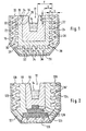
- FIGS. 1 to 5 show tapping troughs for molten iron. such as on the blast furnace for tapping the pig iron. They include a support trough 10 in which a channel 12 for the approximately 1500 ° C. warm iron melt 14 is formed in a refractory lining 16, 18. The latter usually consists of a wear lining 16 in which the channel 12 is formed, and a permanent lining 18, which the wear lining 16th surrounds. Between the permanent feed 18 and the support trough 10 is one Copper lining 20, 120, 320, 420 arranged, which by means of a Cooling device is forced cooled. This forced-cooled copper lining 20, 120, 320, 420 protects the support trough 10 against overheating and thus against thermal deformations.
- the tapping gutter in a concrete channel arranged it also protects the concrete and its fittings against one thermal overload. It also cools the refractory lining 16, 18 and thereby increases their service life. This is especially true for that refractory lining 18 to.
- this concrete channel can support the support trough 10 take over, so that the copper lining 20, 120, 320, 420 immediately can be arranged between the concrete walls and the permanent lining 18. Between the copper lining 20, 120 and the support structure 10, thermal insulation may also be installed (see e.g. in FIG insulating plates provided with the reference numeral 21).
- cross section of the channel through the support trough 10 (or the concrete channel) is formed, the shape of the copper liner 20, 120, 220, 320, 420 sets.
- a preferred form of this cross section is shown in the figures. Of course, one is not in the configuration of the invention the cross-sectional shape shown is limited.
- the copper lining 20 consists of substantially vertical, side plates 22 and 24, and substantially horizontal, bottom plates 26. These elongated plates 22, 24, 26 are of this type put together that they have a kind of copper trough 20 for the Form refractory lining 16, 18. With the reference numerals 28 and 30 in Figure 1, the seams between the side plates 22, 24 and Designated bottom plate 26. Since the length of the individual copper plates 22, 24, 26 is usually much shorter than the length of the trough of course, a plurality of side plates 22, 24, or bottom plates 26 are lined up around the support trough 10 over its entire length undress.
- the copper plates 22, 24, 26 on their inner surface, i.e. the area the facing the refractory lining, massive ribs 32 which are essential protrude into the inner refractory lining 18.
- the ratio height "H" the ribs 32 to the thickness "D" of the permanent lining 18 should preferably between 1: 4 and 3: 4.
- the ribs 32 preferably extend over the entire length of the copper plates 22, 24, 26 and are separated by grooves 34. They contribute to a significant improvement in the cooling of the Refractory lining at. Especially the temperatures in the permanent feed 18 are significantly reduced.
- a no less important function of the ribs 32 consists in a local breakthrough of the molten iron 14 into the Permanent feed 18 to cool the molten iron to solidify before using it comes into contact with the actual base body made of copper and deep inside Overheating cracks caused. It should be noted that contact between a rib 32 and the molten iron, local overheating, or even a partial meltdown that can cause rib 32, as a rule however, no major negative effects on the actual one Has base body made of copper.
- the ribs 32 are sufficiently effective, they must have certain minimum dimensions.
- Execution is the ratio of the height "H” of the ribs 32 to the thickness "S" of the Copper lining between the ribs 32 e.g. about 2: 3. This The ratio should normally be between 1: 2 and 1: 1.
- the ratio width "B" of the ribs to the width "N" of the grooves 34, and the ratio of the height "H” of the Ribs to the width "B” of the ribs should both be between 1: 3 and 3: 1 (in In the embodiment shown, this ratio is approximately 5: 6).
- Thickness "S” of the copper liner between the ribs 32 to the middle one Total thickness “F” of the refractory lining 16 + 18 should be in new condition
- the tapping gutter is between 1:10 and 2: 5. This ratio is shown in FIG approximately in the area of the side plates and in the area of the base plates 3:10.
- the cooling device comprises the Lining 20 cooling channels 36, which both in the side plates 22, 24, as are also arranged in the base plate 26. These cooling channels 36 extend advantageously under the ribs 32 due to the solid body of the plates 22, 24, 26. In other words, the solid ribs 32 cover and protect thus the cooling channels 36.
- a coolant supply (not shown) is supplied the cooling channels 36 with a liquid coolant.
- This coolant supply is a low pressure cooling water supply advantageous, i.e. the feed pressure the cooling water should preferably be less than 1 bar. If cracks in the The low feed pressure of the cooling water does not cause copper plates major leaks, which reduces the risk of explosion. Coolant supply and cooling channels 36 are preferably designed such that the temperature of the copper lining is never 100 ° C exceeds.
- the tapping channel of Figure 1 is made as follows. First they are Copper plates 22, 24, 26 arranged in the support trough 10 and possibly attached. A first refractory mass is then placed in the copper trough 20 poured, which forms the permanent feed 18. This first fireproof The mass penetrates into the grooves 34 and completely fills the latter. A box-shaped first formwork forms the later above the ribs 32 Boundary layer 38 to the wear lining 16. After curing the first refractory mass and after removing the first formwork, it will Wear lining 16 made. For this, a second refractory mass is applied the finished permanent feed 18 poured, with a second formwork Channel 12 trains.
- All copper plates for the tapping channels of Figures 1 to 5 are advantageously continuously cast.
- the copper plates 22, 24, 26 for the tapping channels of Figure 1 can be used in the continuous casting channel Generate through-channels in the casting direction in the finished copper plate 22, 24, 26 form the cooling channels 36.
- These through channels can advantageously an elongated, e.g. oval, cross-section, e.g. in the Figure 2, indicated in the copper plate 124. This will make the free one Cross section of the cooling channels 36 'enlarged without the material thickness of the Copper plate in the area of the cooling channels 36 'decreases.
- the ribs 32 can can also be generated during continuous casting.
- the Continuous casting mold in the continuous casting channel corresponding battlements, which the Form grooves 34.
- cooling channels 36 can also be drilled, and / or the grooves 34 into a forged or rolled Copper block are milled.
- Continuously cast copper plates 22, 24, 26 with cast-in cooling channels can, however, be used extremely cost-effectively produce relatively large lengths. It should be noted that copper plates with large length, need fewer coolant connections, which with one Overflow of the tapping gutter can be destroyed and thus cause an explosion could.
- the tapping gutter of Figure 2 differs from the tapping gutter of Figure 1 essentially by the following features.
- the bottom plate 126 faces no ribs on. It is covered with graphite plates 128, which one Prevent the iron melt from breaking down.
- Another The difference is that the copper lining 120, in the corner area 121, 122 between the bottom plate 126 and the side plates 122, 124 none Has cooling channels. These corner areas 121, 122 are therefore exclusive cooled by the bottom plate 126 and the side plates 122, 124.
- the practice has indeed proven that major breakthroughs in iron smelting always occur in these two corner areas 121, 122 take place.
- the Base plates 26, 126 can optionally also be designed without cooling channels. In In this case, the base plates 26, 126 are removed by heat conduction from the Side plates 22, 24, 122, 124 cooled. If the breakthrough Melting iron in the floor area is therefore a risk of The coincidence of the cooling liquid with the iron melt is greatly reduced.
- the tapping channels of Figures 3 to 5 differ from the Tapping gutter of Figure 1 mainly in that the cooling device of the Copper lining 220, 320, 420 each have an outer cooling circuit with a has liquid coolant, which is behind the back of the Copper liner 220, 320, 420 (i.e. the surface facing the support trough 10 facing) is arranged.
- the cooling device of the Copper lining 220, 320, 420 each have an outer cooling circuit with a has liquid coolant, which is behind the back of the Copper liner 220, 320, 420 (i.e. the surface facing the support trough 10 facing) is arranged.
- the Molten iron in the permanent lining 18 forms one massive protective shield in front of the outer cooling circuit.
- the outer cooling circuit comprises a spray device 240 which from tubes 242 by means of spray nozzles 244 a cooling liquid on the back the copper side plates 222 and 224 spray.
- the on the surface of the copper side plates 222 and 224 draining coolant is in Collection channels 246 collected. Furrows 248 in the back of the copper Side plates 222 and 224 increase the cooled surface and thus the Effect of cooling. It should be noted that one is advantageous Air / water mixture sprayed, in such a way that most of the Water evaporates on the surface.
- the outer cooling circuit comprises one Coolant flowed through external cooling elements, which are at the rear of the Copper lining are attached thermally conductive.
- these cooling elements are designed as solid bars 340, which e.g. cast on or with the copper liner 320 are welded or soldered.
- Each of these outer chilled beams 340 has at least one internal cooling channel 342.
- each of these vortex chambers 440 includes an outer one Pipe socket 442, an inner pipe socket 444, and an inlet line 446 and a return line 448 for a coolant.
- the outer pipe socket 442 has an open end at the back of copper liner 420 attached, e.g. welded.
- a blind bore 441 can be in the outer Enlarge the pipe socket 442 formed chamber 443 into the copper plate.
- the inner pipe socket 444 inserted into the chamber 443.
- the inner pipe socket 444 inserted into the chamber 443.
- the coolant flows in through the inlet line 446 the inner pipe socket 444 and is from the nozzle to the surface of the Sprayed copper liner 420. This will cause strong turbulence in of chamber 443 which intensify heat exchange. The Turbulence in chamber 443 can of course still occur Stakes are increased. The coolant leaves the chamber 443 via the Return line 448.
- FIG. 10 shows the temperature curve in cross-section of a tapping gutter, which is shown under the abscissa axis X. is. You can see the channel with the 1500 ° C hot iron melt 14, the Wear lining 16, the permanent lining 18, and a copper lining 20 '.
- the Temperature curve 50 drawn with a solid line shows the Temperature curve for a copper lining with ribs 32.
- the one with a Dashed dash 52 drawn temperature curve shows the Temperature curve for a copper lining without ribs 32, at the same Temperature (50 ° C) and the same thickness of the base body Copper lining 20 '.
- the 250 ° C line was insulated with an axis line The diagram is drawn.
Landscapes
- Engineering & Computer Science (AREA)
- Chemical & Material Sciences (AREA)
- Mechanical Engineering (AREA)
- Materials Engineering (AREA)
- Metallurgy (AREA)
- Organic Chemistry (AREA)
- Manufacturing & Machinery (AREA)
- General Engineering & Computer Science (AREA)
- Furnace Charging Or Discharging (AREA)
- Furnace Housings, Linings, Walls, And Ceilings (AREA)
- Refinement Of Pig-Iron, Manufacture Of Cast Iron, And Steel Manufacture Other Than In Revolving Furnaces (AREA)
- Blast Furnaces (AREA)
- Vertical, Hearth, Or Arc Furnaces (AREA)
- Manufacture And Refinement Of Metals (AREA)
Description
- Figur 1:
- einen Querschnitt durch eine erste Ausführung einer Abstichrinne;
- Figur 2:
- einen Querschnitt durch eine zweite Ausführung einer Abstichrinne;
- Figur 3:
- einen Querschnitt durch eine dritte Ausführung einer Abstichrinne, die teilweise perspektivisch gezeichnet ist;
- Figur 4:
- einen Querschnitt durch eine vierte Ausführung einer Abstichrinne, die teilweise perspektivisch gezeichnet ist, wobei nur die rechte Hälfte der Rinne gezeigt ist;
- Figur 5:
- einen Querschnitt durch eine fünfte Ausführung einer Abstichrinne, die teilweise perspektivisch gezeichnet ist, wobei nur die rechte Hälfte der Rinne gezeigt ist;
- Figur 6:
- ein Diagramm das Temperaturverlauf im Querschnitt einer Abstichrinne mit Rippen darstellt.
Claims (21)
- Abstichrinne für eine Eisenschmelze, umfassend:gekennzeichnet durch,eine äußere Stützstruktur (10);eine Feuerfestauskleidung (16, 18) in der Stützstruktur (10), wobei in dieser Feuerfestauskleidung ein Kanal (12) für die Eisenschmelze (14) ausgebildet ist;eine Kupferauskleidung (20, 120, 220, 320, 420) welche die Feuerfestauskleidung (18) in der Stützstruktur (10) umgibt; undeine Kühlvorrichtung für die Zwangskühlung der Kupferauskleidung (20, 120, 220, 320, 420);
massive Rippen (32) der Kupferauskleidung (20, 120, 220, 320, 420), welche in die Feuerfestauskleidung (18) hineinragen. - Abstichrinne nach Anspruch 1, dadurch gekennzeichnet, daß die Feuerfestauskleidung ein Verschleißfutter (16) und ein Dauerfutter (18) umfaßt, wobei die Rippen (32) im wesentlichen bis zur Hälfte der Dicke des Dauerfutters (18) reichen.
- Abstichrinne nach Anspruch 1 oder 2, dadurch gekennzeichnet, daß die Feuerfestauskleidung (18), zumindest im Bereich der Rippen auf die Kupferauskleidung aufgegossen ist.
- Abstichrinne nach Anspruch 1, 2 oder 3, dadurch gekennzeichnet, daß die Kupferauskleidung (20, 120, 220, 320, 420) durch massive Kupferplatten (22, 24, 26) ausgebildet wird.
- Abstichrinne nach Anspruch 4, gekennzeichnet durch eine Bodenplatte (26) und zwei Seitenplatten (22, 24) aus Kupfer.
- Abstichrinne nach Anspruch 5, dadurch gekennzeichnet, daß die Bodenplatte (26) mit Graphitplatten (128) belegt ist.
- Abstichrinne nach Anspruch 5 oder 6, dadurch gekennzeichnet, daß die Kupferauskleidung (120) zwischen Bodenplatte (26) und Seitenplatten (22, 24) jeweils einen Eckbereich (121, 126) aufweist, wobei die Kupferauskleidung (120) bis auf diesen Eckbereich unmittelbar mit einem flüssigen Kühlmittel zwangsgekühlt ist.
- Abstichrinne nach einem der Ansprüche 1 bis 7, dadurch gekennzeichnet, daß
das Verhältnis: Höhe "H" der Rippen (32) zur Stärke "S" der Kupferauskleidung (20, 120, 220, 320, 420) in den Nuten (34) zwischen den Rippen (32), zwischen 1:2 und 1:1 liegt. - Abstichrinne nach einem der Ansprüche 1 bis 8, dadurch gekennzeichnet, daß
daß das Verhältnis: Breite "B" der Rippen (32) zur Breite "N" der Nuten (34) zwischen den Rippen (32);
sowie das Verhältnis: Höhe "H" der Rippen (32) zur Breite "B" der Rippen (32);
jeweils zwischen 1:3 und 3:1 liegt. - Abstichrinne nach einem der Ansprüche 1 bis 9, dadurch gekennzeichnet, daß die Kühlvorrichtung Kühlkanäle (36) in der Kupferauskleidung (20) umfaßt, wobei jeder der Kühlkanäle (36) jeweils von einer Rippe (32) überdeckt wird.
- Abstichrinne nach Anspruch 10, dadurch gekennzeichnet, daß die Rippen (32) und Kühlkanäle (36) parallel zur Längsrichtung der Abstichrinne verlaufen.
- Abstichrinne nach Anspruch 11, dadurch gekennzeichnet, daß die Kupferauskleidung (20) durch stranggegossene Kupferplatten (22, 24, 26) ausgebildet wird, wobei Kühlkanäle (36) beim Stranggießen als Durchgangskanäle in Gießrichtung ausgebildet werden.
- Abstichrinne nach Anspruch 11 oder 12, dadurch gekennzeichnet, daß die Rippen (32) beim Stranggießen durch Zinnen in einer Stranggießform ausgebildet werden.
- Abstichrinne nach einem der Ansprüche 1 bis 9, dadurch gekennzeichnet, daß die Kühlvorrichtung einen externen Kühlkreis mit einem flüssigen Kühlmittel aufweist, der die Kupferauskleidung (220, 320, 420) von der Rückseite, d.h. von der Stützstruktur (10) her kühlt.
- Abstichrinne nach Anspruch 14, dadurch gekennzeichnet, daß der externe Kühlkreis eine Sprühvorrichtung (240) aufweist, welche der Rückseite der Kupferauskleidung (220) gegenüberliegt.
- Abstichrinne nach Anspruch 15, dadurch gekennzeichnet, daß die Rückseite der Kupferauskleidung (220) durch Furchen (248) vergrößert ist.
- Abstichrinne nach Anspruch 14, dadurch gekennzeichnet, daß der Kühlkreis von einer Kühlflüssigkeit durchströmte äußere Kühlelemente (340, 440) umfaßt, die an der Rückseite der Kupferauskteidung (320, 420) thermischleitend angebracht sind.
- Abstichrinne nach Anspruch 17, dadurch gekennzeichnet, daß die Kühlelemente massive Kupferbalken (340) mit integrierten Kühlkanälen (342) umfassen.
- Abstichrinne nach Anspruch 18, dadurch gekennzeichnet, daß die Kupferbalken (340) an die Rückseite der Kupferauskleidung (320) angeschweißt oder angelötet sind.
- Abstichrinne nach Anspruch 14, dadurch gekennzeichnet, daß die Kühlelemente Wirbelkammern (440) für die Kühlflüssigkeit umfassen, welche senkrecht zur Rückseite der Kupferauskleidung (420) angeordnet sind.
- Abstichrinne nach Anspruch 20, dadurch gekennzeichnet, daß jede Wirbelkammer (440) folgende Teile umfaßt:einen äußeren Rohrstutzen (442), der mit einem offenen Ende abgedichtet an der Rückseite der Kupferauskleidung (420) befestigt ist, wobei eine geschlossene innere Kammer (243) im äußeren Rohrstutzens (442) ausgebildet wird;einen inneren Rohrstutzen (444), der abgedichtet in diese innere Kammer (243) eingeführt ist, wo er in unmittelbarer Nachbarschaft der Oberfläche der Kupferauskleidung (420) eine Düse (450) ausbildet;eine Zulaufleitung (446) für eine Kühlflüssigkeit, die in den inneren Rohrstutzen (444) einmündet; undeine Rücklaufleitung (448) für die Kühlflüssigkeit, die in den äußeren Rohrstutzen (442) einmündet.
Applications Claiming Priority (3)
| Application Number | Priority Date | Filing Date | Title |
|---|---|---|---|
| LU90195A LU90195B1 (de) | 1998-01-15 | 1998-01-15 | Abstichrinne fuer eine Eisenschmelze |
| LU90195 | 1998-01-15 | ||
| PCT/EP1999/000072 WO1999036580A1 (de) | 1998-01-15 | 1999-01-08 | Abstichrinne für eine eisenschmelze |
Publications (2)
| Publication Number | Publication Date |
|---|---|
| EP1047796A1 EP1047796A1 (de) | 2000-11-02 |
| EP1047796B1 true EP1047796B1 (de) | 2003-03-05 |
Family
ID=19731731
Family Applications (1)
| Application Number | Title | Priority Date | Filing Date |
|---|---|---|---|
| EP99903612A Expired - Lifetime EP1047796B1 (de) | 1998-01-15 | 1999-01-08 | Abstichrinne für eine eisenschmelze |
Country Status (10)
| Country | Link |
|---|---|
| EP (1) | EP1047796B1 (de) |
| JP (1) | JP4199419B2 (de) |
| KR (1) | KR20010034144A (de) |
| AT (1) | ATE233827T1 (de) |
| AU (1) | AU738253B2 (de) |
| BR (1) | BR9908364A (de) |
| CA (1) | CA2318171A1 (de) |
| DE (1) | DE59904444D1 (de) |
| LU (1) | LU90195B1 (de) |
| WO (1) | WO1999036580A1 (de) |
Families Citing this family (7)
| Publication number | Priority date | Publication date | Assignee | Title |
|---|---|---|---|---|
| ES2234467T3 (es) * | 1999-03-16 | 2005-07-01 | Sms Demag Ag | Canal de sangria para un horno de cuba. |
| FI114568B (fi) | 2001-10-19 | 2004-11-15 | Outokumpu Oy | Sularänni |
| US9347708B2 (en) | 2011-09-29 | 2016-05-24 | Hatch Ltd. | Furnace with refractory bricks that define cooling channels for gaseous media |
| DE102015100617B4 (de) | 2015-01-16 | 2021-03-04 | Alpha Deuren International Bv | Torblatt |
| CN110396565B (zh) * | 2019-07-23 | 2024-09-20 | 长兴明天炉料有限公司 | 一种耐侵蚀的高炉出铁沟 |
| CN116042943A (zh) * | 2023-02-01 | 2023-05-02 | 中冶东方工程技术有限公司 | 一种高炉主沟 |
| CN116606973B (zh) * | 2023-05-29 | 2025-04-18 | 包头钢铁(集团)有限责任公司 | 一种高炉出铁场渣铁沟挡墙结构 |
Family Cites Families (3)
| Publication number | Priority date | Publication date | Assignee | Title |
|---|---|---|---|---|
| SU851071A1 (ru) * | 1979-02-01 | 1981-07-30 | Научно-Исследовательский И Опытно- Конструкторский Институт Автоматизациичерной Металлургии | Шаблон |
| LU84042A1 (fr) * | 1982-03-26 | 1983-11-17 | Arbed | Rigole de coulee pour metaux liquides |
| DE19503912C2 (de) * | 1995-02-07 | 1997-02-06 | Gutehoffnungshuette Man | Kühlplatte für Schachtöfen, insbesondere Hochöfen |
-
1998
- 1998-01-15 LU LU90195A patent/LU90195B1/de active
-
1999
- 1999-01-08 AT AT99903612T patent/ATE233827T1/de active
- 1999-01-08 JP JP2000540281A patent/JP4199419B2/ja not_active Expired - Lifetime
- 1999-01-08 BR BR9908364-7A patent/BR9908364A/pt not_active IP Right Cessation
- 1999-01-08 KR KR1020007007763A patent/KR20010034144A/ko not_active Withdrawn
- 1999-01-08 WO PCT/EP1999/000072 patent/WO1999036580A1/de not_active Ceased
- 1999-01-08 EP EP99903612A patent/EP1047796B1/de not_active Expired - Lifetime
- 1999-01-08 CA CA002318171A patent/CA2318171A1/en not_active Abandoned
- 1999-01-08 AU AU24204/99A patent/AU738253B2/en not_active Ceased
- 1999-01-08 DE DE59904444T patent/DE59904444D1/de not_active Expired - Lifetime
Also Published As
| Publication number | Publication date |
|---|---|
| JP4199419B2 (ja) | 2008-12-17 |
| EP1047796A1 (de) | 2000-11-02 |
| KR20010034144A (ko) | 2001-04-25 |
| DE59904444D1 (de) | 2003-04-10 |
| ATE233827T1 (de) | 2003-03-15 |
| CA2318171A1 (en) | 1999-07-22 |
| LU90195B1 (de) | 1999-07-16 |
| BR9908364A (pt) | 2000-11-28 |
| AU738253B2 (en) | 2001-09-13 |
| WO1999036580A1 (de) | 1999-07-22 |
| AU2420499A (en) | 1999-08-02 |
| JP2002509193A (ja) | 2002-03-26 |
Similar Documents
| Publication | Publication Date | Title |
|---|---|---|
| EP1153142B1 (de) | Verfahren zum herstellen einer kühlplatte für einen ofen zur eisen- oder stahlerzeugung | |
| DE29611704U1 (de) | Kühlplatte für metallurgische Öfen | |
| DE19503912C2 (de) | Kühlplatte für Schachtöfen, insbesondere Hochöfen | |
| DE2641224A1 (de) | Ofenwand fuer zur stahlherstellung dienende oefen, insbesondere ultra- hochleistungs-lichtbogenoefen | |
| DE20213759U1 (de) | Kühlplatte für metallurgische Öfen | |
| DE602004004094T2 (de) | Ofenwand mit kühlplatten für einen metallurgischen ofen | |
| EP1047796A1 (de) | Abstichrinne für eine eisenschmelze | |
| DE69822107T2 (de) | Kühlplatte für metallurgische Schachtöfen | |
| EP1218549B1 (de) | Metallurgischer ofen mit kupferkühlplatten | |
| EP1499462A1 (de) | Anpassung des wärmeüberganges bei stranggiesskokillen, insbesondere im giessspiegelbereich | |
| DE60003505T2 (de) | Großflächige Kokille zum vertikalen Stranggießen mit Einsatz von Metallen | |
| DE69806334T2 (de) | Rinne zum Führen von flüssigen Metallen | |
| DE2313320A1 (de) | Durch umgiessen eines oder mehrerer rohre, insbesondere kuehlrohr, geformtes gussteil | |
| WO2013178205A1 (de) | Anordnung zum kleinstückigen erstarren von bei der metallerzeugung anfallenden flüssigen schlacken | |
| EP1322790B1 (de) | Kühlelement für schachtöfen | |
| DE69802953T2 (de) | Elektrolichtbogen mit einer kühlvorrichtung enthaltend panele | |
| DE3120221A1 (de) | Verfahren und giessform zur herstellung eines dickwandigen behaelters aus sphaerolithischem gusseisen und fuer das verfahren geeignete giessform | |
| DE2620509C2 (de) | Feuerfester Bauteil oder Formkörper | |
| DE60014953T2 (de) | Mit Kühlplatten ausgestatteter Schachtofen und Verfahren zu seiner Herstellung | |
| DE1508796B2 (de) | Verfahren undVorrichtung zum Kühlen eines Stahlstranges in der SekundärkUhlzone einer Stranggießanlage | |
| AT410717B (de) | Kühlplatte mit verstärkungsteil | |
| EP1480915B1 (de) | Mit einer glasschmelze beaufschlagte, gekühlte begrenzungswand einer glasschmelzanlage | |
| DE69900502T2 (de) | Wandaufbau für metallschmelzofen und hochofen mit solchem aufbau | |
| DE2804282C3 (de) | Kühler für Schachtöfen | |
| DE3420845A1 (de) | Kokille fuer diskontinuierliches abgiessen von metallschmelze, insbesondere fuer ne-metallschmelze |
Legal Events
| Date | Code | Title | Description |
|---|---|---|---|
| PUAI | Public reference made under article 153(3) epc to a published international application that has entered the european phase |
Free format text: ORIGINAL CODE: 0009012 |
|
| 17P | Request for examination filed |
Effective date: 20000710 |
|
| AK | Designated contracting states |
Kind code of ref document: A1 Designated state(s): AT BE DE ES FI FR GB IT NL SE |
|
| GRAG | Despatch of communication of intention to grant |
Free format text: ORIGINAL CODE: EPIDOS AGRA |
|
| 17Q | First examination report despatched |
Effective date: 20020529 |
|
| GRAG | Despatch of communication of intention to grant |
Free format text: ORIGINAL CODE: EPIDOS AGRA |
|
| GRAH | Despatch of communication of intention to grant a patent |
Free format text: ORIGINAL CODE: EPIDOS IGRA |
|
| GRAH | Despatch of communication of intention to grant a patent |
Free format text: ORIGINAL CODE: EPIDOS IGRA |
|
| GRAA | (expected) grant |
Free format text: ORIGINAL CODE: 0009210 |
|
| AK | Designated contracting states |
Designated state(s): AT BE DE ES FI FR GB IT NL SE |
|
| PG25 | Lapsed in a contracting state [announced via postgrant information from national office to epo] |
Ref country code: FR Free format text: LAPSE BECAUSE OF FAILURE TO SUBMIT A TRANSLATION OF THE DESCRIPTION OR TO PAY THE FEE WITHIN THE PRESCRIBED TIME-LIMIT Effective date: 20030305 Ref country code: FI Free format text: LAPSE BECAUSE OF FAILURE TO SUBMIT A TRANSLATION OF THE DESCRIPTION OR TO PAY THE FEE WITHIN THE PRESCRIBED TIME-LIMIT Effective date: 20030305 |
|
| REG | Reference to a national code |
Ref country code: GB Ref legal event code: FG4D Free format text: NOT ENGLISH |
|
| REF | Corresponds to: |
Ref document number: 59904444 Country of ref document: DE Date of ref document: 20030410 Kind code of ref document: P |
|
| PG25 | Lapsed in a contracting state [announced via postgrant information from national office to epo] |
Ref country code: SE Free format text: LAPSE BECAUSE OF FAILURE TO SUBMIT A TRANSLATION OF THE DESCRIPTION OR TO PAY THE FEE WITHIN THE PRESCRIBED TIME-LIMIT Effective date: 20030605 |
|
| GBT | Gb: translation of ep patent filed (gb section 77(6)(a)/1977) | ||
| PG25 | Lapsed in a contracting state [announced via postgrant information from national office to epo] |
Ref country code: ES Free format text: LAPSE BECAUSE OF FAILURE TO SUBMIT A TRANSLATION OF THE DESCRIPTION OR TO PAY THE FEE WITHIN THE PRESCRIBED TIME-LIMIT Effective date: 20030930 |
|
| PLBE | No opposition filed within time limit |
Free format text: ORIGINAL CODE: 0009261 |
|
| STAA | Information on the status of an ep patent application or granted ep patent |
Free format text: STATUS: NO OPPOSITION FILED WITHIN TIME LIMIT |
|
| EN | Fr: translation not filed | ||
| PG25 | Lapsed in a contracting state [announced via postgrant information from national office to epo] |
Ref country code: BE Free format text: LAPSE BECAUSE OF NON-PAYMENT OF DUE FEES Effective date: 20040131 |
|
| 26N | No opposition filed |
Effective date: 20031208 |
|
| BERE | Be: lapsed |
Owner name: S.A. PAUL *WURTH Effective date: 20040131 |
|
| PGFP | Annual fee paid to national office [announced via postgrant information from national office to epo] |
Ref country code: GB Payment date: 20101214 Year of fee payment: 13 |
|
| PGFP | Annual fee paid to national office [announced via postgrant information from national office to epo] |
Ref country code: NL Payment date: 20111221 Year of fee payment: 14 |
|
| PGFP | Annual fee paid to national office [announced via postgrant information from national office to epo] |
Ref country code: DE Payment date: 20111214 Year of fee payment: 14 |
|
| PGFP | Annual fee paid to national office [announced via postgrant information from national office to epo] |
Ref country code: IT Payment date: 20120126 Year of fee payment: 14 |
|
| PGFP | Annual fee paid to national office [announced via postgrant information from national office to epo] |
Ref country code: AT Payment date: 20111219 Year of fee payment: 14 |
|
| REG | Reference to a national code |
Ref country code: NL Ref legal event code: V1 Effective date: 20130801 |
|
| REG | Reference to a national code |
Ref country code: AT Ref legal event code: MM01 Ref document number: 233827 Country of ref document: AT Kind code of ref document: T Effective date: 20130131 |
|
| GBPC | Gb: european patent ceased through non-payment of renewal fee |
Effective date: 20130108 |
|
| PG25 | Lapsed in a contracting state [announced via postgrant information from national office to epo] |
Ref country code: AT Free format text: LAPSE BECAUSE OF NON-PAYMENT OF DUE FEES Effective date: 20130131 Ref country code: NL Free format text: LAPSE BECAUSE OF NON-PAYMENT OF DUE FEES Effective date: 20130801 Ref country code: DE Free format text: LAPSE BECAUSE OF NON-PAYMENT OF DUE FEES Effective date: 20130801 |
|
| REG | Reference to a national code |
Ref country code: DE Ref legal event code: R119 Ref document number: 59904444 Country of ref document: DE Effective date: 20130801 |
|
| PG25 | Lapsed in a contracting state [announced via postgrant information from national office to epo] |
Ref country code: GB Free format text: LAPSE BECAUSE OF NON-PAYMENT OF DUE FEES Effective date: 20130108 |
|
| PG25 | Lapsed in a contracting state [announced via postgrant information from national office to epo] |
Ref country code: IT Free format text: LAPSE BECAUSE OF NON-PAYMENT OF DUE FEES Effective date: 20130108 |