EP1046836A2 - Vorrichtung zum Handhaben von Rohren usw. - Google Patents
Vorrichtung zum Handhaben von Rohren usw. Download PDFInfo
- Publication number
- EP1046836A2 EP1046836A2 EP00303230A EP00303230A EP1046836A2 EP 1046836 A2 EP1046836 A2 EP 1046836A2 EP 00303230 A EP00303230 A EP 00303230A EP 00303230 A EP00303230 A EP 00303230A EP 1046836 A2 EP1046836 A2 EP 1046836A2
- Authority
- EP
- European Patent Office
- Prior art keywords
- tubular body
- collar
- article
- parts
- longitudinal
- Prior art date
- Legal status (The legal status is an assumption and is not a legal conclusion. Google has not performed a legal analysis and makes no representation as to the accuracy of the status listed.)
- Withdrawn
Links
Images
Classifications
-
- B—PERFORMING OPERATIONS; TRANSPORTING
- B65—CONVEYING; PACKING; STORING; HANDLING THIN OR FILAMENTARY MATERIAL
- B65H—HANDLING THIN OR FILAMENTARY MATERIAL, e.g. SHEETS, WEBS, CABLES
- B65H75/00—Storing webs, tapes, or filamentary material, e.g. on reels
- B65H75/02—Cores, formers, supports, or holders for coiled, wound, or folded material, e.g. reels, spindles, bobbins, cop tubes, cans, mandrels or chucks
- B65H75/34—Cores, formers, supports, or holders for coiled, wound, or folded material, e.g. reels, spindles, bobbins, cop tubes, cans, mandrels or chucks specially adapted or mounted for storing and repeatedly paying-out and re-storing lengths of material provided for particular purposes, e.g. anchored hoses, power cables
- B65H75/38—Cores, formers, supports, or holders for coiled, wound, or folded material, e.g. reels, spindles, bobbins, cop tubes, cans, mandrels or chucks specially adapted or mounted for storing and repeatedly paying-out and re-storing lengths of material provided for particular purposes, e.g. anchored hoses, power cables involving the use of a core or former internal to, and supporting, a stored package of material
- B65H75/44—Constructional details
- B65H75/4402—Guiding arrangements to control paying-out and re-storing of the material
- B65H75/4405—Traversing devices; means for orderly arranging the material on the drum
- B65H75/441—Traversing devices; means for orderly arranging the material on the drum with a handle on the guide for manual operation
-
- B—PERFORMING OPERATIONS; TRANSPORTING
- B25—HAND TOOLS; PORTABLE POWER-DRIVEN TOOLS; MANIPULATORS
- B25B—TOOLS OR BENCH DEVICES NOT OTHERWISE PROVIDED FOR, FOR FASTENING, CONNECTING, DISENGAGING OR HOLDING
- B25B9/00—Hand-held gripping tools other than those covered by group B25B7/00
-
- F—MECHANICAL ENGINEERING; LIGHTING; HEATING; WEAPONS; BLASTING
- F16—ENGINEERING ELEMENTS AND UNITS; GENERAL MEASURES FOR PRODUCING AND MAINTAINING EFFECTIVE FUNCTIONING OF MACHINES OR INSTALLATIONS; THERMAL INSULATION IN GENERAL
- F16G—BELTS, CABLES, OR ROPES, PREDOMINANTLY USED FOR DRIVING PURPOSES; CHAINS; FITTINGS PREDOMINANTLY USED THEREFOR
- F16G11/00—Means for fastening cables or ropes to one another or to other objects; Caps or sleeves for fixing on cables or ropes
- F16G11/04—Means for fastening cables or ropes to one another or to other objects; Caps or sleeves for fixing on cables or ropes with wedging action, e.g. friction clamps
- F16G11/044—Means for fastening cables or ropes to one another or to other objects; Caps or sleeves for fixing on cables or ropes with wedging action, e.g. friction clamps friction clamps deforming the cable, wire, rope or cord
- F16G11/048—Means for fastening cables or ropes to one another or to other objects; Caps or sleeves for fixing on cables or ropes with wedging action, e.g. friction clamps friction clamps deforming the cable, wire, rope or cord by moving a surface into the cable
-
- F—MECHANICAL ENGINEERING; LIGHTING; HEATING; WEAPONS; BLASTING
- F16—ENGINEERING ELEMENTS AND UNITS; GENERAL MEASURES FOR PRODUCING AND MAINTAINING EFFECTIVE FUNCTIONING OF MACHINES OR INSTALLATIONS; THERMAL INSULATION IN GENERAL
- F16L—PIPES; JOINTS OR FITTINGS FOR PIPES; SUPPORTS FOR PIPES, CABLES OR PROTECTIVE TUBING; MEANS FOR THERMAL INSULATION IN GENERAL
- F16L1/00—Laying or reclaiming pipes; Repairing or joining pipes on or under water
- F16L1/024—Laying or reclaiming pipes on land, e.g. above the ground
- F16L1/06—Accessories therefor, e.g. anchors
-
- F—MECHANICAL ENGINEERING; LIGHTING; HEATING; WEAPONS; BLASTING
- F41—WEAPONS
- F41B—WEAPONS FOR PROJECTING MISSILES WITHOUT USE OF EXPLOSIVE OR COMBUSTIBLE PROPELLANT CHARGE; WEAPONS NOT OTHERWISE PROVIDED FOR
- F41B5/00—Bows; Crossbows
- F41B5/14—Details of bows; Accessories for arc shooting
-
- B—PERFORMING OPERATIONS; TRANSPORTING
- B65—CONVEYING; PACKING; STORING; HANDLING THIN OR FILAMENTARY MATERIAL
- B65H—HANDLING THIN OR FILAMENTARY MATERIAL, e.g. SHEETS, WEBS, CABLES
- B65H2301/00—Handling processes for sheets or webs
- B65H2301/50—Auxiliary process performed during handling process
- B65H2301/51—Modifying a characteristic of handled material
- B65H2301/511—Processing surface of handled material upon transport or guiding thereof, e.g. cleaning
- B65H2301/5115—Cleaning
-
- B—PERFORMING OPERATIONS; TRANSPORTING
- B65—CONVEYING; PACKING; STORING; HANDLING THIN OR FILAMENTARY MATERIAL
- B65H—HANDLING THIN OR FILAMENTARY MATERIAL, e.g. SHEETS, WEBS, CABLES
- B65H2701/00—Handled material; Storage means
- B65H2701/30—Handled filamentary material
- B65H2701/33—Hollow or hose-like material
-
- Y—GENERAL TAGGING OF NEW TECHNOLOGICAL DEVELOPMENTS; GENERAL TAGGING OF CROSS-SECTIONAL TECHNOLOGIES SPANNING OVER SEVERAL SECTIONS OF THE IPC; TECHNICAL SUBJECTS COVERED BY FORMER USPC CROSS-REFERENCE ART COLLECTIONS [XRACs] AND DIGESTS
- Y10—TECHNICAL SUBJECTS COVERED BY FORMER USPC
- Y10S—TECHNICAL SUBJECTS COVERED BY FORMER USPC CROSS-REFERENCE ART COLLECTIONS [XRACs] AND DIGESTS
- Y10S16/00—Miscellaneous hardware, e.g. bushing, carpet fastener, caster, door closer, panel hanger, attachable or adjunct handle, hinge, window sash balance
- Y10S16/12—Hand grips, preformed and semi-permanent
-
- Y—GENERAL TAGGING OF NEW TECHNOLOGICAL DEVELOPMENTS; GENERAL TAGGING OF CROSS-SECTIONAL TECHNOLOGIES SPANNING OVER SEVERAL SECTIONS OF THE IPC; TECHNICAL SUBJECTS COVERED BY FORMER USPC CROSS-REFERENCE ART COLLECTIONS [XRACs] AND DIGESTS
- Y10—TECHNICAL SUBJECTS COVERED BY FORMER USPC
- Y10T—TECHNICAL SUBJECTS COVERED BY FORMER US CLASSIFICATION
- Y10T24/00—Buckles, buttons, clasps, etc.
- Y10T24/39—Cord and rope holders
- Y10T24/3936—Pivoted part
Definitions
- the present invention relates to a device for engaging a pipe, cable or other elongate article, to facilitate longitudinal displacement of the article.
- a device for engaging a pipe, cable or other elongate article to displace that article longitudinally comprising a tubular body formed of a plurality of longitudinal parts arranged to be opened apart and then closed together around the elongate article to be displaced, and at least one collar positioned within the tubular body and formed of a plurality of parts carried by respective parts of the tubular body, the collar having a radially inner surface arranged to form an interference engagement with the outer surface of the article to be displaced, and a radially outer surface arranged to engage the inner surface of the tubular body, at least the outer surface of the collar or the inner surface of the tubular body being tapered towards a trailing end of the device.
- the longitudinal parts of the tubular body are opened and then engaged around the elongate article to be displaced, such that the inner surface of the collar forms an interference engagement with the surface of that article.
- the tubular body is then moved longitudinally in a forward direction. This causes the collar to slide towards the trailing end of the tubular body, because of the interference engagement between the collar and the surface of the elongate article around which the device is engaged: this has the effect of wedging the collar firmly against the surface of the pipe. Continued movement of the device therefore displaces the elongate article in the same direction.
- the device may be slid freely back along the article, then another forward stroke executed, and so on until the article has been displaced the required distance: finally, the parts of the tubular body are opened apart to remove the tubular body from the article.
- the tubular body may be arranged to receive a single gripping collar. Instead it may be arranged to receive a number of gripping collars, spaced apart along its length: in this case the number of gripping collars which are used, and the positions in which they are placed, may be selected to suit the application. Where the tubular body receives a number of collars, spaced apart along its length, then, in each part of the body, the respective parts of the collars may be joined by a longitudinal spine. The collar parts of each part of the body thus form a unit so that those parts slide as a unit and can be removed and replaced as a unit.
- the or each collar has a radially outer surface which is tapered to match a tapering section of the inner surface of the tubular body in which it is inserted.
- the radially inner surface of the or each collar is formed with a series of annular teeth, preferably directed towards the forward end of the device.
- each part of the collar is formed to a reduced thickness (e.g. by one or more grooves in its inner surface) at a discrete location or at intervals around its circumference, to impart flexibility to it and enable it to adopt a reduced diameter as it is slid, in use, towards the trailing end of the device.
- a reduced thickness e.g. by one or more grooves in its inner surface
- each of the longitudinal parts of the tubular body is provided with a retaining formation for the respective part of the or each collar.
- the collars can be removed and replaced by collars selected to match the diameter of the pipe or other article on which the device is to be used.
- a device for engaging a pipe, cable or other elongate article to displace that article longitudinally comprising a tubular body formed of a plurality of longitudinal parts arranged to be opened apart then closed together around the elongate article to be displaced, the inner surface of the elongate body being arranged to form an engagement with the outer surface of the article to be displaced.
- the longitudinal parts of the tubular body are opened and then closed around the elongate article to be displaced, such that the inner surface of the tubular body engages the outer surface of the elongate article.
- the longitudinal parts of the tubular body are then held firmly together and the device is moved longitudinally in a forward direction, to displace the elongate article.
- the forces holding the parts of the tubular body together are relaxed, so that the device may be slid back along the article, for another forward stroke to be executed.
- the inner surface of the tubular body is formed with a number of annular teeth, preferably directed towards the forward end of the device.
- the tubular body may comprise two longitudinal parts, although it may instead comprise three or even more longitudinal parts.
- the adjacent parts are coupled together so that they can be flexed relative to each other, for opening and closing the tubular body.
- the longitudinal parts may be formed as one-piece with an integral hinge coupling them together.
- the tubular body is made of plastics material by injection moulding.
- Either of the above-defined devices may be a hand-held device for manual use.
- the tubular body has an outer surface for gripping by hand.
- a radially-outwardly projecting flange is provided at least at the forward end (and preferably at both ends) of the tubular body, to act as a safety-guard.
- the tubular body may be relatively short, such that it is gripped by one hand only: alternatively, it may be sufficiently long that it may be gripped by two hands, one behind the other.
- the parts of the tubular body may be arranged to clip together: a hook may be coupled to one end of the tubular body, to enable it to be towed; in this case, the device may be used for pulling live electric cables, particularly cables up to perhaps 1000 volts rating.
- either of the above-defined devices may be incorporated in a powered apparatus for the longitudinal displacement of a pipe, cable or other elongate article.
- the trailing end of either of the above-defined devices is formed with an inwardly-directed annular edge for engaging the surface of the article to be displaced.
- This edge then acts to scrape dirt etc. from the surface of the article as the device is slid in the retracting direction, prior to a forward stroke to displace the article.
- this trailing end of the tubular body may be arranged to receive an annular insert (formed in a number of parts which are retained by the respective longitudinal parts of the tubular body), the inner edge of this insert forming a scraping edge. The insert can then be selected of appropriate diameter for the article on which the device is to be used.
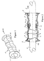
- the device comprises a rigid tubular body 10 which is split longitudinally (along a plane indicated at B which is perpendicular to the plane of the pipes) into two identical parts 11, 12: the two parts 11, 12 are coupled together along one side, for example by means of an integral hinge (not shown), to enable the two parts of the tubular body 10 to be opened apart then closed together around the pipe P, or around a cable or other elongate article which is to be longitudinally displaced.
- the tubular body 10 is formed with three frusto-conical sections 13, 14, 15 spaced apart along its length and all tapering in the same direction (which is opposite to the direction A in which the device is arranged to displace the pipe, cable or other article) .
- An annular shoulder 13a,14a,15a is formed at the larger-diameter end of each of the frusto-conical sections 13,14,15.
- annular, radially-outwardly projecting flange 16,18 is formed at each end of the tubular body 10.
- the outer surface of the tubular body varies in diameter in undulating manner between the two flanges 16,18 to provide a succession of annular ridges and grooves and such that the wall thickness of the tubular body is generally uniform throughout its length, to facilitate manufacture of the tubular body by injection moulding: the profile of the outer surface of the tubular body also improves its ability to be gripped by hand.
- the flanges 16,18 at the opposite ends of the tubular body serve to prevent the user's hand or hands slipping off the device when in use and also guard the hands against being injured by striking adjacent structures in use of the device.
- the flange 16, at the trailing end of the device is formed with a radially-inwardly-directed annular edge 16a for a purpose which will be described below.
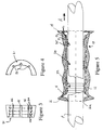
- the device further includes at least one rigid gripping collar 20, which is divided into two semi-circular parts or inserts 21,22, one of which is shown in Figures 3 and 4.
- the collar 20 has a frusto-conical outer surface matched to the tapering sections 13,14,15 of the tubular body 10.
- the inner surface of the collar is formed with a series of annular teeth 24 of equal diameter, directed towards the larger-diameter end of the collar (i.e. the direction A in which the pipe P is to be displaced).
- the inner surface of the collar is moreover formed with a series of grooves 26, spaced apart around its circumference, and effectively dividing the series of annular teeth 24 at intervals into successive sections: the grooves 26 provide a degree of flexibility between the adjacent toothed sections of the collar; instead of a series of grooves, each part of the collar may be formed with a single groove only.
- the collar 20 is positioned in one of the tapering sections of the tubular body 10, with one part 21 of the collar in the body part 11 and the other part 22 of the collar in the body part 12.
- Each part of the tubular body is formed with projections (not shown) at both circumferential ends of each tapering section, the opposite circumferential ends of the collar part 21 or 22 engaging behind these projections to retain that collar part within the tapering section of the body part.
- Figure 2 shows the device with a single gripping collar, which is engaged in the centre tapering section 14 of the tubular body.
- two such gripping collars may be provided, for example engaged in the end tapering sections 13,15: alternatively, three gripping collars may be provided, engaged in all three tapering sections 13,14,15.
- the two parts of the or each collar may be removed (after flexing it to disengage it from the retaining projections of the respective body part) and replaced: collars of different internal diameters may be used for pipes or cables etc. of different outer diameters.
- the two parts 11,12 of the tubular body are hinged open then closed together around the pipe P or other article to be displaced.
- the tubular body 10 is gripped by hand, the user's hand being applied around the outer surface of the body: however, only sufficient pressure is needed simply to hold the two parts of the body closed around the pipe P.
- the teeth 24 of the collar or collars 20 of the device only form an interference engagement with the surface of the pipe P and do not bite into this surface.
- the or each collar 20 is caused to slide towards the smaller-diameter end of its tapering section of the tubular body, because of the interference engagement between the collar and the surface of the pipe P; this has the effect of forcing the collar radially inwardly and so enhancing its grip on the pipe P.
- the collar is able to deform to the required smaller diameter because of the flexibility imparted by its series of grooves 26.
- the user is accordingly able to displace the pipe P whilst maintaining only a relatively light grip around the device: the harder the user pushes or pulls the device, the more firmly the collar or collars 20 embrace the pipe P.
- the user can then freely slide the device back along the pipe, then push or pull the device again in the direction A in order to displace the pipe further in that direction.
- the annular edge 16a scrapes lightly along the surface of the pipe to remove any dirt or grease which may be present on that surface.
- this end of the tubular body may be formed with an internal groove to accept an annular insert (formed in two parts, one for each part of the tubular body) which is formed with a scraping edge: this insert can then be selected of a diameter which matches the pipe etc. on which the device is to be used.
- Figure 5 shows a modified embodiment of the invention, in which the rigid tubular body 10 of the device is again split into two longitudinal parts 11,12: however, the collar 20 of the above-described device is omitted and instead the inner surface of the tubular body is provided with three series 33,34,35 of annular teeth, directed towards the forward end of the device.
- the two parts 11,12 (which again are preferably coupled together e.g. by an integral hinge) are opened apart then closed around the pipe P or other article to be displaced: the device is gripped firmly by hand so that teeth 33,34,35 embrace the surface of the pipe P; then the device is moved in the forward direction A to displace the pipe P. The user then relaxes his grip around the device, so that it can be slid freely back in the retracting direction, before the grip is tightened again and another forward stroke executed, and so on.
- the tubular body 10 may comprise an outer sleeve O and an inner sleeve I, the outer sleeve, formed with the teeth 34, being of slightly elastomeric material.
Landscapes
- Engineering & Computer Science (AREA)
- General Engineering & Computer Science (AREA)
- Mechanical Engineering (AREA)
- Supports For Pipes And Cables (AREA)
- Details Of Indoor Wiring (AREA)
Applications Claiming Priority (6)
| Application Number | Priority Date | Filing Date | Title |
|---|---|---|---|
| GB9908866 | 1999-04-20 | ||
| GBGB9908866.8A GB9908866D0 (en) | 1999-04-20 | 1999-04-20 | Device for displacing a pipe etc. |
| GBGB9917186.0A GB9917186D0 (en) | 1999-04-20 | 1999-07-22 | Device for displacing a pipe etc |
| GB9917186 | 1999-07-22 | ||
| GB9917906A GB2349112B (en) | 1999-04-20 | 1999-08-02 | Device for displacing a pipe etc |
| GB9917906 | 1999-08-02 |
Publications (2)
| Publication Number | Publication Date |
|---|---|
| EP1046836A2 true EP1046836A2 (de) | 2000-10-25 |
| EP1046836A3 EP1046836A3 (de) | 2002-03-13 |
Family
ID=27269702
Family Applications (1)
| Application Number | Title | Priority Date | Filing Date |
|---|---|---|---|
| EP00303230A Withdrawn EP1046836A3 (de) | 1999-04-20 | 2000-04-17 | Vorrichtung zum Handhaben von Rohren usw. |
Country Status (2)
| Country | Link |
|---|---|
| US (1) | US6471268B1 (de) |
| EP (1) | EP1046836A3 (de) |
Families Citing this family (23)
| Publication number | Priority date | Publication date | Assignee | Title |
|---|---|---|---|---|
| US20030014842A1 (en) * | 2001-06-28 | 2003-01-23 | Niendorf Amy J. | Ergonomic high volume evacuator handle |
| US6883782B2 (en) * | 2002-08-30 | 2005-04-26 | Bendyco Incorporated | Cable clamping apparatus and method |
| TWM241097U (en) * | 2003-07-24 | 2004-08-21 | Modern Molded Products Ltd | Improved structure of sheath for handle of golf club |
| EA010718B1 (ru) * | 2005-03-30 | 2008-10-30 | Хаджи Михайло Церанич | Рукоятка для пакетов и сумок с поворотной накладкой |
| US7513015B2 (en) * | 2005-08-02 | 2009-04-07 | Peluso Daniel A | Gripping handle for supporting a rotating tool extension |
| US7478794B1 (en) | 2006-09-26 | 2009-01-20 | Rectorseal Corporation | Apparatus and methods for gripping an elongated item |
| US20080173126A1 (en) * | 2007-01-23 | 2008-07-24 | Kuryakyn Holdings, Inc. | Motorcycle handlebar grip cover |
| CA2716771C (en) * | 2008-03-05 | 2016-02-09 | Southwire Company | Device for gripping and installing wire |
| US20090247827A1 (en) * | 2008-03-27 | 2009-10-01 | U.S. Endoscopy Group, Inc. | Endoscope Gripping Device |
| US8757594B2 (en) | 2008-10-23 | 2014-06-24 | Southwire Company, Llc | Pulling jacket for use while installing wires in conduit |
| US20120013140A1 (en) * | 2010-07-19 | 2012-01-19 | Athalon Sportsgear, Inc. | Hand Grip Device |
| WO2012148597A1 (en) * | 2011-04-29 | 2012-11-01 | Electric Transportation Engineering Corporation, D/B/A Ecotality North America | Device to facilitate moving an electrical cable of an electric vehicle charging station and method of providing the same |
| US20120211020A1 (en) * | 2011-02-22 | 2012-08-23 | Julius Garcia | Helical hair tie |
| US9707375B2 (en) | 2011-03-14 | 2017-07-18 | Rochester Medical Corporation, a subsidiary of C. R. Bard, Inc. | Catheter grip and method |
| US20120324666A1 (en) * | 2011-06-27 | 2012-12-27 | Leigh-Anna Provenzano | Grip for hair styling device |
| US9872969B2 (en) | 2012-11-20 | 2018-01-23 | Rochester Medical Corporation, a subsidiary of C.R. Bard, Inc. | Catheter in bag without additional packaging |
| USD755528S1 (en) * | 2013-03-08 | 2016-05-10 | Leigh-Anna Provenzano | Grip for hair styling device |
| US9821142B2 (en) | 2013-03-14 | 2017-11-21 | Hollister, Incorporated | Urinary catheters with protective tip |
| US9168354B2 (en) * | 2013-03-14 | 2015-10-27 | Hollister Incorporated | Sleeveless urinary catheters with protective tip |
| US20140353561A1 (en) * | 2013-05-31 | 2014-12-04 | Verizon Patent And Licensing Inc. | System and method for guiding a cable |
| US10396518B2 (en) * | 2014-05-14 | 2019-08-27 | Pds Electronics, Inc. | Cable gripper tool |
| JP7350722B2 (ja) | 2017-09-19 | 2023-09-26 | シー・アール・バード・インコーポレーテッド | 尿カテーテルブリッジ装置、そのシステムおよび方法 |
| GB201814750D0 (en) * | 2018-09-11 | 2018-10-24 | Univ Leuven Kath | Manipulation device |
Family Cites Families (27)
| Publication number | Priority date | Publication date | Assignee | Title |
|---|---|---|---|---|
| US292148A (en) * | 1884-01-15 | stibolt | ||
| US1235309A (en) * | 1913-10-17 | 1917-07-31 | David I Garretson | Handle for utensils which are subjected to heat. |
| US1413690A (en) * | 1921-02-01 | 1922-04-25 | Frank E Slocum | Twine grip |
| US1654340A (en) * | 1926-08-07 | 1927-12-27 | John Edward Ogden | Clamp |
| US1800254A (en) * | 1926-12-18 | 1931-04-14 | Frank J Holmes | Handle and the like |
| US2398436A (en) * | 1945-02-09 | 1946-04-16 | Ernest J Mason | Self-locking, identical half handle structure |
| US3682023A (en) * | 1971-02-08 | 1972-08-08 | Waldon Devices Inc | Turnbuckle wrench |
| US3776586A (en) * | 1972-02-09 | 1973-12-04 | Uddemann Byggteknik Ab | Gripping device |
| US3854768A (en) * | 1974-01-02 | 1974-12-17 | L King | Pipe pulling device |
| US3981043A (en) * | 1975-01-14 | 1976-09-21 | Curry Christian O | Slidable tool grip |
| US4143446A (en) * | 1977-05-26 | 1979-03-13 | Down Dennis L R | Rope or cable clamp device |
| GB1591845A (en) | 1977-06-09 | 1981-06-24 | Amp Inc | Tensioning device |
| AU4312079A (en) * | 1978-01-11 | 1979-07-19 | Ccl Systems Limited | Compression splicing |
| SE429590B (sv) | 1978-01-16 | 1983-09-12 | Larsson Karl Henning | Handverktyg for dragning av ledningar och/eller tradar |
| GB2071253A (en) * | 1980-03-07 | 1981-09-16 | Amf Inc | Tweezer wedge device |
| JPH0246372Y2 (de) * | 1985-01-16 | 1990-12-06 | ||
| US4823919A (en) * | 1986-09-15 | 1989-04-25 | Premiere Casing Services, Inc. | Slip construction for supporting tubular members |
| DE3641340A1 (de) * | 1986-12-03 | 1988-06-16 | Volker Markl | Handgriff zum erfassen von seilen |
| US4890355A (en) * | 1988-10-26 | 1990-01-02 | Schulten Elizabeth W | Releasably mountable hand grip for handles |
| US5083825A (en) * | 1990-04-05 | 1992-01-28 | Bystrom Benjamin L | Bag carrier handle |
| NL9002429A (nl) * | 1990-11-08 | 1992-06-01 | Hendrik Meijer | Materiaalhanteerder/geleider. |
| US5068949A (en) * | 1990-12-14 | 1991-12-03 | Horace Martin J | Rope connector having quick engaging and releasing means |
| US5364148A (en) * | 1993-01-19 | 1994-11-15 | Anna Bartocci | Carrying handle |
| US5544926A (en) | 1995-01-30 | 1996-08-13 | Ravencroft; Gary N. | Shaft gripper for pulling an arrow |
| FR2743321B1 (fr) * | 1996-01-05 | 1998-02-13 | Soc D Expl Des Ets Racodon Sa | Poignee pour outils de frappe a main |
| US5775756A (en) * | 1996-04-03 | 1998-07-07 | Rozenich; Robert | Secure gripping system |
| US5860190A (en) * | 1997-03-21 | 1999-01-19 | Cano; Rolando M. | Expanded implement handle grip |
-
2000
- 2000-04-17 EP EP00303230A patent/EP1046836A3/de not_active Withdrawn
- 2000-04-18 US US09/551,055 patent/US6471268B1/en not_active Expired - Fee Related
Also Published As
| Publication number | Publication date |
|---|---|
| EP1046836A3 (de) | 2002-03-13 |
| US6471268B1 (en) | 2002-10-29 |
Similar Documents
| Publication | Publication Date | Title |
|---|---|---|
| US6471268B1 (en) | Device for displacing a pipe etc | |
| EP3423741B1 (de) | Fixiervorrichtung und -verfahren | |
| US8898876B2 (en) | Barbed fittings, fitting insertion tools and methods relating to same | |
| US20060265840A1 (en) | Cable retention system | |
| EP0436645B1 (de) | Selbstspannende schlauchkupplung | |
| US10182705B2 (en) | Gripping device | |
| EP1727759B1 (de) | Seilorganisator | |
| US20120104746A1 (en) | Quick connector assembly | |
| TW202143592A (zh) | 纜線固定裝置 | |
| CA2322024C (en) | Internal pipe pulling device | |
| CA2512427A1 (en) | Cable clamps | |
| EP0454630A1 (de) | Verbesserte lösbare Schnellkupplung | |
| GB2349112A (en) | Longitudinal displacing device | |
| CN111305333B (zh) | 可伸出的马桶螺旋钻 | |
| US20190084739A1 (en) | Zip tie for one hand use | |
| US20240063625A1 (en) | Cap for Fastening to Cables and Other Elongated Elements | |
| GB2245639A (en) | Snap fastening clamp band | |
| WO2007049053A1 (en) | Hose connector | |
| NL8302993A (nl) | Manchetvormige koppeling voor buisleidingen. | |
| EP4206512B1 (de) | Anschluss für schläuche und dergleichen | |
| NZ264022A (en) | Pipe coupling comprising a body part, a rotatable sleeve and a circular band | |
| AU723411B2 (en) | Cable feeding apparatus | |
| GB2510362A (en) | Electrical cable capping system | |
| US20090057010A1 (en) | Cover for terminated cables | |
| JP4406576B2 (ja) | 既設配管へのコルゲート管の挿入工法およびこの挿入工法に用いる挿入治具 |
Legal Events
| Date | Code | Title | Description |
|---|---|---|---|
| PUAI | Public reference made under article 153(3) epc to a published international application that has entered the european phase |
Free format text: ORIGINAL CODE: 0009012 |
|
| AK | Designated contracting states |
Kind code of ref document: A2 Designated state(s): AT BE CH CY DE DK ES FI FR GB GR IE IT LI LU MC NL PT SE |
|
| AX | Request for extension of the european patent |
Free format text: AL;LT;LV;MK;RO;SI |
|
| PUAL | Search report despatched |
Free format text: ORIGINAL CODE: 0009013 |
|
| AK | Designated contracting states |
Kind code of ref document: A3 Designated state(s): AT BE CH CY DE DK ES FI FR GB GR IE IT LI LU MC NL PT SE |
|
| AX | Request for extension of the european patent |
Free format text: AL;LT;LV;MK;RO;SI |
|
| RIC1 | Information provided on ipc code assigned before grant |
Free format text: 7F 16G 11/04 A, 7F 16B 9/02 B, 7F 16L 3/18 B, 7H 02G 1/08 B, 7B 25B 9/00 B |
|
| AKX | Designation fees paid | ||
| REG | Reference to a national code |
Ref country code: DE Ref legal event code: 8566 |
|
| STAA | Information on the status of an ep patent application or granted ep patent |
Free format text: STATUS: THE APPLICATION IS DEEMED TO BE WITHDRAWN |
|
| 18D | Application deemed to be withdrawn |
Effective date: 20021101 |