EP3423741B1 - Fixiervorrichtung und -verfahren - Google Patents
Fixiervorrichtung und -verfahren Download PDFInfo
- Publication number
- EP3423741B1 EP3423741B1 EP17707395.4A EP17707395A EP3423741B1 EP 3423741 B1 EP3423741 B1 EP 3423741B1 EP 17707395 A EP17707395 A EP 17707395A EP 3423741 B1 EP3423741 B1 EP 3423741B1
- Authority
- EP
- European Patent Office
- Prior art keywords
- fixing
- elongate members
- elongate member
- elongate
- article
- Prior art date
- Legal status (The legal status is an assumption and is not a legal conclusion. Google has not performed a legal analysis and makes no representation as to the accuracy of the status listed.)
- Active
Links
Images


Classifications
-
- F—MECHANICAL ENGINEERING; LIGHTING; HEATING; WEAPONS; BLASTING
- F16—ENGINEERING ELEMENTS AND UNITS; GENERAL MEASURES FOR PRODUCING AND MAINTAINING EFFECTIVE FUNCTIONING OF MACHINES OR INSTALLATIONS; THERMAL INSULATION IN GENERAL
- F16L—PIPES; JOINTS OR FITTINGS FOR PIPES; SUPPORTS FOR PIPES, CABLES OR PROTECTIVE TUBING; MEANS FOR THERMAL INSULATION IN GENERAL
- F16L3/00—Supports for pipes, cables or protective tubing, e.g. hangers, holders, clamps, cleats, clips, brackets
- F16L3/02—Supports for pipes, cables or protective tubing, e.g. hangers, holders, clamps, cleats, clips, brackets partly surrounding the pipes, cables or protective tubing
- F16L3/04—Supports for pipes, cables or protective tubing, e.g. hangers, holders, clamps, cleats, clips, brackets partly surrounding the pipes, cables or protective tubing and pressing it against a wall or other support
-
- F—MECHANICAL ENGINEERING; LIGHTING; HEATING; WEAPONS; BLASTING
- F16—ENGINEERING ELEMENTS AND UNITS; GENERAL MEASURES FOR PRODUCING AND MAINTAINING EFFECTIVE FUNCTIONING OF MACHINES OR INSTALLATIONS; THERMAL INSULATION IN GENERAL
- F16B—DEVICES FOR FASTENING OR SECURING CONSTRUCTIONAL ELEMENTS OR MACHINE PARTS TOGETHER, e.g. NAILS, BOLTS, CIRCLIPS, CLAMPS, CLIPS OR WEDGES; JOINTS OR JOINTING
- F16B5/00—Joining sheets or plates, e.g. panels, to one another or to strips or bars parallel to them
- F16B5/06—Joining sheets or plates, e.g. panels, to one another or to strips or bars parallel to them by means of clamps or clips
- F16B5/0685—Joining sheets or plates to strips or bars
-
- F—MECHANICAL ENGINEERING; LIGHTING; HEATING; WEAPONS; BLASTING
- F16—ENGINEERING ELEMENTS AND UNITS; GENERAL MEASURES FOR PRODUCING AND MAINTAINING EFFECTIVE FUNCTIONING OF MACHINES OR INSTALLATIONS; THERMAL INSULATION IN GENERAL
- F16L—PIPES; JOINTS OR FITTINGS FOR PIPES; SUPPORTS FOR PIPES, CABLES OR PROTECTIVE TUBING; MEANS FOR THERMAL INSULATION IN GENERAL
- F16L3/00—Supports for pipes, cables or protective tubing, e.g. hangers, holders, clamps, cleats, clips, brackets
- F16L3/08—Supports for pipes, cables or protective tubing, e.g. hangers, holders, clamps, cleats, clips, brackets substantially surrounding the pipe, cable or protective tubing
- F16L3/12—Supports for pipes, cables or protective tubing, e.g. hangers, holders, clamps, cleats, clips, brackets substantially surrounding the pipe, cable or protective tubing comprising a member substantially surrounding the pipe, cable or protective tubing
- F16L3/127—Supports for pipes, cables or protective tubing, e.g. hangers, holders, clamps, cleats, clips, brackets substantially surrounding the pipe, cable or protective tubing comprising a member substantially surrounding the pipe, cable or protective tubing and extending away from the attachment surface
-
- H—ELECTRICITY
- H02—GENERATION; CONVERSION OR DISTRIBUTION OF ELECTRIC POWER
- H02G—INSTALLATION OF ELECTRIC CABLES OR LINES, OR OF COMBINED OPTICAL AND ELECTRIC CABLES OR LINES
- H02G3/00—Installations of electric cables or lines or protective tubing therefor in or on buildings, equivalent structures or vehicles
- H02G3/30—Installations of cables or lines on walls, floors or ceilings
- H02G3/32—Installations of cables or lines on walls, floors or ceilings using mounting clamps
-
- F—MECHANICAL ENGINEERING; LIGHTING; HEATING; WEAPONS; BLASTING
- F16—ENGINEERING ELEMENTS AND UNITS; GENERAL MEASURES FOR PRODUCING AND MAINTAINING EFFECTIVE FUNCTIONING OF MACHINES OR INSTALLATIONS; THERMAL INSULATION IN GENERAL
- F16L—PIPES; JOINTS OR FITTINGS FOR PIPES; SUPPORTS FOR PIPES, CABLES OR PROTECTIVE TUBING; MEANS FOR THERMAL INSULATION IN GENERAL
- F16L3/00—Supports for pipes, cables or protective tubing, e.g. hangers, holders, clamps, cleats, clips, brackets
- F16L3/22—Supports for pipes, cables or protective tubing, e.g. hangers, holders, clamps, cleats, clips, brackets specially adapted for supporting a number of parallel pipes at intervals
- F16L3/237—Supports for pipes, cables or protective tubing, e.g. hangers, holders, clamps, cleats, clips, brackets specially adapted for supporting a number of parallel pipes at intervals for two pipes
Definitions
- the present invention relates to apparatus and methods for securing articles to a surface, such as a wall of a building, and in particular the invention relates to securing cabling, pipework and the like.
- a fixing such as a bracket or saddle clip.
- a deformable plug such as a rawl plug or butterfly plug
- passing a screw though an aperture in the fixing and into the deformable plug causes the plug to deform or expand, applying pressure against the walls of the hole, thereby retaining the fixing in place.
- fixings of this general type can however be time consuming. Each fixing can take at least around 30-60 seconds to install and this can be problematic when a large number of fixings are required. For example, when a long run of cabling or pipework or the like is to be secured to a wall, hundreds or in some cases thousands of fixings are required and the cumulative time to install them can significantly contribute to the overall time for an installation.
- a clip can be used having opposed resiliently biased legs, such as disclosed in EP1434960B1 .
- the legs can be squeezed together to introduce the clip into a hole, and when released spring outwardly and into engagement with the walls of the hole. Barbs on the outside of the legs may provide additional engagement with the wall and increase the force required to remove the clip from the hole.
- One such device, for fixing cables, is the Linian Fire ClipTM of Linian Supply Co. Limited, Glasgow, United Kingdom.
- US2014017025 describes a smart material actuated fastener that includes a shape memory material and a non-shape memory material.
- EP0105865 describes a moulded fastening element for the fastening of installation pipes or cables on a wall or ceiling, having a longitudinally divided stem provided with spreaders on the stem surface for a positive connection with the wall of a bore hole.
- EP0433621 describes a U-shaped universal fastener for cooperative association with a pair of leg receptor slots in a substrate to fasten an elongated body therebetween, said fastener comprising two separated substantially parallel elongated flexible leg members joined at one end by a tying member, each of said elongated leg members having an interior and an exterior side, and on each of said interior and exterior sides, and a plurality of flanged flexible stop members vertically inclined toward said tieing member.
- a fixing for inserting into a cylindrical hole and securing an article to a surface
- the fixing comprising a coupling arrangement, for coupling the fixing to a said article; and two elongate members extending from the coupling arrangement; the elongate members being resiliently biased towards a position in which they are spaced apart from one another along at least a part of their length; each elongate member comprising a resiliently deformable inner formation spaced apart from a proximal end and a distal end of the elongate member, the inner formations extending toward an adjacent elongate member and positioned to engage therewith and resiliently deform, when the elongate members are brought together and inserted in a said cylindrical hole in use, to thereby supplement the outward forces applied to walls of the cylindrical hole by the elongate member.
- the elongate members comprise distal portions free of inner formations
- the elongate members may be brought together (typically manually squeezed together) and inserted into a cavity, such as a cylindrical hole as formed by a drill or the like.
- the elongate members are resiliently biased apart so as to into engage with the cavity walls and retain the fixing in position.
- the relative size of the cavity to the elongate members may be selected so that the inner formations are also resiliently deformed on insertion of the elongate members, and thereby supplement the outward forces applied to the cavity walls.
- the inner formations are positioned so that the outward forces they apply are distributed along the elongate members both proximally and distally of the inner formations. Accordingly, the provision of inner formations on the elongate members increases the "pull out resistance" of the fixing (i.e. the force required to remove it from the cavity).
- the elongate members may be biased towards a position in which they diverge from one another away from their proximal ends.
- the elongate members may be biased towards a position in which they diverge from one another away from their distal ends.
- the elongate members may be generally bowed, and biased towards a position in which their proximal and distal ends converge.
- the elongate members may be joined at their proximal and/or distal ends.
- the elongate members may be biased towards a position in which they are spaced apart along all, or the majority of their length.
- the inner formation of a first elongate member may be positioned to engage with the inner formation of a second elongate member, when the elongate members are brought together.
- An inner formation may extend from an inside of an elongate member.
- An inner formation may comprise a resilient member extending from an inside of an elongate member.
- an inner formation may comprise an arm extending from an inside of an elongate member.
- An inner formation may be a branch from an inside of an elongate member.
- An elongate member may be branched; one or more branches thereof functioning as an inner formation.
- An inner formation may be formed as a kink, bend or corrugation along an elongate member.
- An elongate member may be resilient.
- a kink, bend or corrugation in a resilient elongate member may function as a resiliently deformable inner formation.
- An inner formation may comprise a deformable region, comprising for example an elastomeric or resilient plastics material.
- the elongate members may comprise a sleeve comprising one or more resiliently deformable materials, such as elastomers and the like.
- An elastomeric material may be glued or mechanically fixed to an inside of an elongate member.
- An elongate member may comprise two, or more than two, inner formations (which may be the same or of more than one type). Two or more inner formations may be spaced apart along a length of an elongate member.
- Terms such as inside, inner, or inward refer to a surface(s), formation or region of an elongate member having an orientation or extending in a direction generally towards another elongate member. Conversely, terms such as outside or outer, refer to a direction or orientation of an elongate member generally away from other elongate member(s).
- the elongate members comprise distal portions free of inner formations.
- the distal portions may be brought closer together without significant deformation of the inner formations.
- This arrangement facilitates insertion of the distal portions into a cavity. Moreover, the application of a force generally along the elongate members (i.e. the insertion direction) may be translated into resilient deformation of the inner formations.
- a distal portion of an elongate member may be inwardly curved or kinked.
- the distal portion may transition smoothly to the portion of the elongate member proximal thereto.
- the distal portions When brought together, the distal portions may form a wedge, so assist in guiding the elongate members into a cavity.
- outer surface of at least the distal portions may be smooth.
- An elongate member may comprise one or more barbs or projections extending outwardly. Such barbs or projects may assist in engaging with a cavity wall, in use.
- the one or more barbs/projections are preferably oriented away from the distal end of the elongate member so as to engage most strongly with a cavity wall when a force is applied to pull the fixing from the cavity.
- the one or more barbs/projections may be ramped away from the distal end of the elongate member.
- the one or more barbs/projections may be resilient.
- the relative position of inner formations and barbs along an elongate member may be selected so that the outward forces applied by the inner formations in use are effectively transferred to the barbs.
- An inner formation may be positioned adjacent to a barb, along an elongate member.
- An inner formation may be positioned between barbs, along an elongate member.
- An elongate member may comprise barbs proximal and distal to an inner formation.
- an outer surface of an elongate member may be conformable, for example to an inner surface of a cavity.
- an elongate member may comprise an outer conformable region along all or a part of its length.
- a conformable region may be plastically deformable or flowable, or elastically deformable.
- the outer conformable region may conform to an inside of a cavity, and convey additional pull resistance.
- a fixing for securing an article to a surface
- the fixing comprising a coupling arrangement, for coupling the fixing to a said article; and two elongate members extending from the coupling arrangement; the elongate members being resiliently biased towards a position in which they are spaced apart from one another along at least a part of their length; each elongate member comprising an outer conformable region along all or a part of its length.
- Each elongate member may have a proximal end adjacent to the coupling arrangement and a distal end, and comprise a resiliently deformable inner formation spaced apart from the proximal and distal ends, the inner formations extending toward an adjacent elongate member and positioned to engage therewith and resiliently deform, when the elongate members are brought together in use.
- An outer conformable region may be formed from a plastics material.
- An outer conformable region may be formed from an elastomeric material.
- An outer conformable region may be affixed to an elongate member by any suitable method.
- an elongate member may comprise a sleeve (such as a plastics or elastomeric sleeve).
- a conformable region such as a block of a deformable material, may be adhesively or mechanically attached to an outer surface of an elongate member.
- An elongate member may comprise a keying formation, such as a ridged or corrugated surface, to improve bonding to an outer conformable region.
- a keying formation for example comprising ridges across (rather than along a length of) an outside of an elongate member may also resist slippage between a conformable region and the elongate member when a fixing is urged into or out of a cavity, in use.
- the fixing may comprise more than two elongate members.
- the fixing may comprise one or more pairs of opposed elongate members.
- the fixing may comprise three or more elongate members diverging from the coupling arrangement, operable to be brought together in use.
- each elongate member is the same however the invention is not limited to a fixing having two or more identical elongate members.
- the coupling arrangement may comprise a loop or hook or T-Bar or screw-type head (for back box fixing).
- the coupling arrangement in particular a loop, may extend from a proximal end of a first elongate member to a proximal end of a second elongate member.
- the elongate members and the coupling arrangement may be formed from a single strip of material.
- At least a part of the coupling arrangement may be resilient, and so contribute to the biasing of the elongate members.
- the fixing may comprise a resilient hook or loop or T-Bar head or screw-type head.
- the fixing may be adapted to secure cables, piping or the like (e.g. the hook or loop described above) of may be a releasable coupling such as a bracket.
- the coupling may comprise a male and female cooperating formations, removably securable to one another, the removable portion of which is securable to an article; so as to facilitate temporary removal of the article from the fixing.
- the fixing may be a clip, such as a cable clip.
- the clip, and the coupling arrangement in particular, may be sized to clip a cable, conduit, duct, pipe or the like to a surface (e.g. a wall).
- the clip or its coupling arrangement may be sized or configured to clip a more than one such article together and to a surface.
- the elongate members may be sized to be inserted into a hole, typically a round hole, as made for example by a drill bit.
- the fixing may be of unitary construction (i.e. formed from a single piece of material).
- the fixing may be provided with an external coating, such as a plastics coating, paint, lacquer, an anodized coating, or any other suitable protective coating.
- the coating may be of a particular colour (for example for consistency with cables which are colour coded for safety reasons).
- the fixing may comprise or be substantially formed from a resilient material, such as steel.
- the article may be coupled to the coupling arrangement before or after insertion of the elongate members into the cavity.
- the method may comprise plastically or elastically deforming the or each outer conformable region.
- the method may comprise bending branches or arms extending inwardly from one or both elongate members.
- the method may comprise providing a fixing in accordance with other aspects of the invention.
- the surface may be a wall, such as the wall of a building.
- the wall may be an external wall.
- the wall may be a concrete or stone wall. It will be understood that the invention is not limited to such applications, and the fixing may be configured for use with any type of wall material such as plasterboard, wood, brick, breeze block or the like.
- Figure 1 shows a side view of a fixing 1 (in the embodiment shown, a cable clip) for securing an article to a surface.
- the fixing has a coupling arrangement 3 and elongate members, legs 5, extending therefrom.
- the coupling arrangement is formed as a loop 3 extending between the legs 5.
- the loop is sized to receive one or more cables, conduits, pipes or the like, which may passed between the legs 5 and into the loop 3 to be coupled to the fixing 1 (generally in the direction A).
- the fixing 1 is shown "at rest", i.e. in the configuration adopted in the absence of any externally applied forces or constraints.
- the elongate members 5 have proximal ends 7, adjacent to the coupling arrangement 3 and extend to distal ends 8.
- the elongate members 5 are resiliently biased towards the position shown in Figure 1 , in which they diverge from one another away from their proximal ends 7.
- An inner formation 9 extends or branches inwardly of each leg 5.
- the inner formations 9 are spaced apart from the proximal and distal ends 7, 8.
- arms 9 are themselves resiliently deformable. Accordingly, when the legs 5 are squeezed together in use (as described in further detail below), the arms 9 contact one another and are deflected towards alignment with the legs.
- Figure 2 shows the configuration of the fixing 1 when the legs 5 are squeezed together in this way.
- the resilient deformation of the arms 9 contributes to the biasing force urging the legs 5 apart.
- the relatively central position of the arms 9 ensures that the outward biasing forces applied by the arms is distributed along the legs 5 both proximally and distally of the arms 9.
- the arms 9 engage with one another and are resiliently deformed. In other embodiments (not shown) the arms may be staggered, so as to engage with the adjacent leg when the legs are squeezed together.
- the distal portions 11 of the legs 5 are inwardly kinked, and transition to the regions proximal thereto via a ramp 13.
- the distal fixing is narrowest at it distal ends 8 and the distal regions 11 present an outwardly tapering wedge shape, to assist in insertion into a cavity (as described in further detail below).
- the inner formations, arms 9, are spaced apart from the distal regions along the legs 5, and so do not impede bringing the distal ends together.
- the legs 5 are also provided with outwardly extending barbs 15.
- the barbs 15 are ramped away from the distal ends 8 and so add relatively little resistance to insertion of the legs 5 into a cavity, but act to catch against imperfections in a cavity wall and/or bite into a cavity wall, and resist removal of the fixing 1, as described below.
- the barbs 15 are positioned both proximally and distally of the arms 9, so that the outward forces applied by the arms in use are effectively transmitted to the barbs.
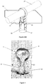
- Figure 3(a) shows a hole 17 having been drilled in a surface 19 (e.g. a building wall).
- Figure 3(b) shows a perspective view of the fixing 1 with a wire 21 been coupled to the coupling arrangement (loop 3), by insertion between the elongate members 5 in the direction A as described above with reference to Figure 1 .
- the fixing 1 is shown with the legs 5 squeezed together (as would typically be done between finger and thumb).
- the legs 5 are then inserted into the hole 17 (direction B, Figure 3(c) , in which the wire 21 is omitted for clarity.) As shown in Figure 3(d) , once the pressure holding the legs 5 together has been released, they spring apart and into engagement with the inside walls 18 of the hole 17. During insertion, the lip of the hole 17 and/or the walls 18 may slide against the ramp 13, the smooth transitional surface provided by the ramp thereby facilitating insertion of the fixing into the hole.
- the legs 5' may optionally be curved, in this instance at a proximal region 23 to the coupling arrangement 3', so as to increase the length of the elongate members 5 in contact with the walls of the cavity 17' in which the fixing is placed.
- FIG. 5 An alternative embodiment of a fixing 100 is shown in Figure 5 .
- the legs 105 of fixing 100 each have two inner formations, arms 109a and 109b.
- the inner formations are spaced apart from the proximal and distal ends 107, 108 of the legs 105.
- the fixing 100 has barbs adjacent to each of the arms 109a, 109b, such that that the outward biasing forces applied by the arms are transmitted to the corresponding adjacent barbs.
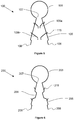
- FIG. 6 Another embodiment of a fixing 200 is shown in Figure 6 .
- the legs 205 of the fixing 201 have an inner formation in the form of an inwardly kinked portion 209.
- the inner formations may be resiliently deformed and thus act to urge the legs apart, in the manner described above.
- the barbs may be formed by cuts in the material of the legs, bent away from the outer face as shown.
- the entire clip may be formed from a single strip of a resilient material, such as spring steel.
- FIG. 7 A still further embodiment of a fixing 300 is shown in Figure 7 .
- the fixing 300 is provided with a coupling arrangement in the form of a hook 304.
- An article such as cable, pipework or a frame can be coupled to the fixing by insertion generally in the direction C.
- the hook is formed from the same strip of resilient steel as the legs 305, and can be bent open so as to admit or remove the article. This arrangement enables an article to be inserted and removed from the coupling arrangement independently of securing the fixing arrangement to a surface.
- the distal portions of the legs 305 of the fixing 300 are inwardly curved towards their distal ends 308. When the legs are brought together, the distal portions together form a generally wedged shape, to assist in inserting the fixing into a cavity.
- FIG. 8 Another fixing 400 (not according to the invention) is shown in Figure 8 .
- the elongate members, legs 405, are provided with outer conformable regions 431, glued to the outer surfaces of the legs.
- the outer conformable regions are in the form of elastomeric blocks.
- alternative plastics materials may be used.
- conformable regions formed from PTFE or any other suitable plastics material may be capable of plastically deforming in use, so as to conform to the inner surface of a hole.
- the legs also have ribbed outer surfaces 433, so as to increase the surface area of contact to the outer conformable regions.
- the ribs run perpendicular to the legs (i.e. into and out of the page, from the side view of Figure 8 ), and so help to resist slippage between the elastomeric blocks 431 and the legs 405 when forces are applied along the legs, in use.
- the elastomeric blocks conform to the inner surface of the cavity and so contribute to the pull resistance of the fixing.
- the fixing may be provided both with resiliently conformable inner formations and deformable outer regions.
Landscapes
- Engineering & Computer Science (AREA)
- General Engineering & Computer Science (AREA)
- Mechanical Engineering (AREA)
- Architecture (AREA)
- Civil Engineering (AREA)
- Structural Engineering (AREA)
- Supports For Pipes And Cables (AREA)
- Clamps And Clips (AREA)
Claims (14)
- Befestigung (1, 100, 200, 300) zum Einsetzen in ein zylindrisches Loch und Befestigen eines Artikels (21) an einer Oberfläche (19);wobei die Befestigung eine Kopplungsanordnung (3, 103, 203, 304), um die Befestigung an den Artikel zu koppeln; und zwei längliche Elemente (5, 105, 205, 305) umfasst, die sich von der Kopplungsanordnung erstrecken;wobei die länglichen Elemente elastisch zu einer Position vorgespannt sind, in der sie entlang zumindest einem Teil ihrer Länge voneinander beabstandet sind;wobei jedes längliche Element eine elastisch verformbare innere Formation (9, 109a, 109b, 209, 309a, 309b) umfasst, die von einem proximalen Ende (7, 107, 207, 307) und einem distalen Ende (8, 108, 208, 308) des länglichen Elements beabstandet ist;wobei die länglichen Elemente (5, 105, 205, 305) distale Abschnitte (11, 311) frei von inneren Formationen umfassen, wobei sich die inneren Formationen zu einem benachbarten länglichen Element erstrecken und positioniert sind, um damit in Eingriff zu treten und sich elastisch zu verformen, wenn die länglichen Elemente im Gebrauch zusammengebracht und in das zylindrische Loch eingesetzt werden, um dadurch die nach außen gerichteten Kräfte zu ergänzen, die durch die länglichen Elemente auf Wände des zylindrischen Lochs ausgeübt werden.
- Befestigung (1, 100, 200, 300) nach Anspruch 1, wobei die länglichen Elemente (5, 105, 205, 305) zu einer Position vorgespannt sind, in der sie von ihren proximalen Enden (7, 107, 207, 307) weg voneinander divergieren.
- Befestigung (1, 100, 200, 300) nach Anspruch 1 oder 2, wobei die inneren Formationen (9, 109a, 109b, 209, 309a, 309b) positioniert sind, um einander in Eingriff zu nehmen, wenn die länglichen Elemente (5, 105, 205, 305) zusammengebracht werden.
- Befestigung (1, 100, 200, 300) nach einem vorhergehenden Anspruch, wobei sich die inneren Formationen (9, 109a, 109b, 209, 309a, 309b) von einer Innenseite jedes länglichen Elements (5, 105, 205, 305) erstrecken.
- Befestigung (1, 100, 300) nach dem vorhergehenden Anspruch, wobei jede innere Formation (9, 109a, 109b, 309a, 309b) ein elastisches Element umfasst, das sich von einer Innenseite des länglichen Elements (5, 105, 305) erstreckt.
- Befestigung (200) nach einem der Ansprüche 1 bis 4, wobei jede innere Formation (209) als Knick, Biegung oder Wellung entlang des länglichen Elements (205) gebildet ist.
- Befestigung (1, 100, 200, 300) nach dem vorhergehenden Anspruch, wobei jede innere Formation einen verformbaren Bereich umfasst, wobei der verformbare Bereich ein elastomeres oder elastisches Kunststoffmaterial umfasst.
- Befestigung (100, 300) nach dem vorhergehenden Anspruch, wobei jedes längliche Element (105, 305) zwei oder mehr als zwei innere Formationen (109a, 109b, 309a, 309b) des gleichen oder von mehr als einem Typ umfasst.
- Befestigung (1, 100, 200, 300) nach einem vorhergehenden Anspruch, wobei die länglichen Elemente nach innen gekrümmte oder geknickte distale Abschnitte umfassen.
- Befestigung (1, 100, 200, 300) nach einem vorhergehenden Anspruch, wobei die länglichen Elemente (5, 105, 205, 305) einen oder mehrere Widerhaken oder Vorsprünge (15, 115, 215, 315) umfassen, die sich nach außen erstrecken.
- Befestigung (1, 100, 200, 300) nach einem vorhergehenden Anspruch, wobei jedes längliche Element (5, 105, 205, 305) einen äußeren anpassungsfähigen Bereich (431) entlang seiner gesamten Länge oder eines Teils davon umfasst; wobei der äußere anpassungsfähige Bereich optional plastisch verformbar oder elastisch verformbar ist.
- Verfahren zum Befestigen eines Artikels (21) an einer Oberfläche (19), umfassend:Bereitstellen eines zylindrischen Lochs (17) in einer Oberfläche;Bereitstellen einer Befestigung (1, 100, 200, 300), die zumindest zwei längliche Elemente (5, 105, 205, 305) aufweist, die sich von einer Kopplungsanordnung (3, 103, 203, 304) erstrecken; wobei die länglichen Elemente elastisch zu einer Position vorgespannt sind, in der sie entlang zumindest einem Teil ihrer Länge voneinander beabstandet sind; wobei jedes längliche Element eine elastisch verformbare innere Formation (9, 109a, 109b, 209, 309a, 309b) umfasst, die von einem proximalen Ende (7, 107, 207, 307) und einem distalen Ende (8, 108, 208, 308) des länglichen Elements beabstandet ist; und die länglichen Elemente (5, 105, 205, 305) distale Abschnitte (11, 311) frei von inneren Formationen umfassen;Zusammenbringen der länglichen Elemente näher aneinander und Einsetzen der länglichen Elemente in das zylindrische Loch;elastisches Verformen der inneren Formation und dadurch Ausüben einer nach außen gerichteten Kraft auf die länglichen Elemente; undKoppeln des Artikels an die Kopplungsanordnung.
- Verfahren nach Anspruch 12, umfassend das Bereitstellen einer Befestigung (1, 100, 200, 300) nach einem der Ansprüche 1-11.
- Verfahren nach Anspruch 12 oder 13, wobei der Artikel (21) ein Kabel ist.
Applications Claiming Priority (2)
| Application Number | Priority Date | Filing Date | Title |
|---|---|---|---|
| GBGB1603692.3A GB201603692D0 (en) | 2016-03-03 | 2016-03-03 | Fixing apparatus and method |
| PCT/GB2017/050407 WO2017149271A1 (en) | 2016-03-03 | 2017-02-16 | Fixing apparatus and method |
Publications (2)
| Publication Number | Publication Date |
|---|---|
| EP3423741A1 EP3423741A1 (de) | 2019-01-09 |
| EP3423741B1 true EP3423741B1 (de) | 2021-10-27 |
Family
ID=55858950
Family Applications (1)
| Application Number | Title | Priority Date | Filing Date |
|---|---|---|---|
| EP17707395.4A Active EP3423741B1 (de) | 2016-03-03 | 2017-02-16 | Fixiervorrichtung und -verfahren |
Country Status (4)
| Country | Link |
|---|---|
| US (1) | US10837577B2 (de) |
| EP (1) | EP3423741B1 (de) |
| GB (1) | GB201603692D0 (de) |
| WO (1) | WO2017149271A1 (de) |
Families Citing this family (23)
| Publication number | Priority date | Publication date | Assignee | Title |
|---|---|---|---|---|
| GB2537761B (en) * | 2016-05-24 | 2017-09-06 | Hampton Steel Ltd | Strainer post connector |
| EP3539191A4 (de) | 2016-11-11 | 2020-07-01 | Commscope Technologies LLC | Adapter zur befestigung von kabeln und kabelaufhängungen |
| CN113746045A (zh) * | 2016-11-30 | 2021-12-03 | 康普技术有限责任公司 | 用于安装多根线缆的吊架 |
| WO2018118528A1 (en) | 2016-12-21 | 2018-06-28 | Commscope Technologies Llc | Hanger for mounting multiple cables |
| CN107366782B (zh) * | 2017-07-31 | 2023-08-15 | 江西清华泰豪三波电机有限公司 | 一种卡箍装置 |
| GB201713754D0 (en) * | 2017-08-28 | 2017-10-11 | Linian Supply Co Ltd | Fixing apparatus and method |
| GB2577695B (en) * | 2018-10-01 | 2021-08-04 | D Line Europe Ltd | Cable restraint and method of securing a cable |
| WO2020146531A1 (en) * | 2019-01-09 | 2020-07-16 | Hubbell Incorporated | Cable clips for wire management |
| WO2021007014A1 (en) * | 2019-07-09 | 2021-01-14 | Commscope Technologies Llc | Shroud for cable hangers |
| DE102019122992A1 (de) * | 2019-08-27 | 2021-03-04 | Zf Airbag Germany Gmbh | Baugruppe aus einer Abdeckkappe eines Rohrgasgenerators und einem Deflektorelement, Rohrgasgenerator und Verfahren zur Herstellung eines Rohrgasgenerators |
| GB2592263B (en) | 2020-02-24 | 2024-06-12 | Linian Lab Ltd | Fastening device |
| GB202016972D0 (en) * | 2020-10-26 | 2020-12-09 | Linian Lab Ltd | Optical fibre clip |
| US20220160956A1 (en) * | 2020-11-24 | 2022-05-26 | Carefusion 303, Inc. | Intravenous tube untangling device |
| USD1008007S1 (en) | 2022-06-24 | 2023-12-19 | Hubbell Incorporated | Cable hanger |
| USD1007285S1 (en) | 2022-06-24 | 2023-12-12 | Hubbell Incorporated | Cable hanger |
| USD1007286S1 (en) | 2022-06-24 | 2023-12-12 | Hubbell Incorporated | Cable hanger |
| USD1007284S1 (en) | 2022-06-24 | 2023-12-12 | Hubbell Incorporated | Cable hanger |
| US12249822B2 (en) | 2022-06-24 | 2025-03-11 | Hubbell Incorporated | Electrical cable hangers |
| USD1008004S1 (en) | 2022-06-24 | 2023-12-19 | Hubbell Incorporated | Cable hanger |
| USD1008006S1 (en) | 2022-06-24 | 2023-12-19 | Hubbell Incorporated | Cable hanger |
| USD1061228S1 (en) | 2022-08-22 | 2025-02-11 | Hubbell Incorporated | Electrical component hanger |
| USD1067761S1 (en) | 2022-08-22 | 2025-03-25 | Hubbell Incorporated | Electrical component hanger |
| USD1017388S1 (en) | 2022-10-01 | 2024-03-12 | Hubbell Incorporated | Cable hanger |
Family Cites Families (17)
| Publication number | Priority date | Publication date | Assignee | Title |
|---|---|---|---|---|
| US3633250A (en) * | 1970-03-02 | 1972-01-11 | Russell H Romney | Mechanical connector system including bifurcate hinged connector means |
| US3737128A (en) * | 1971-10-20 | 1973-06-05 | Fastway Fasteners | Cable support clip |
| AT353875B (de) * | 1978-02-17 | 1979-12-10 | Fiala Johann | Duebelschelle |
| AT376069B (de) * | 1982-10-04 | 1984-10-10 | Schnabl Ludwig Ing | Befestigungselement |
| US5150865A (en) | 1989-12-18 | 1992-09-29 | Xerox Corporation | Universal fastener |
| US5845883A (en) * | 1997-02-12 | 1998-12-08 | Illinois Tool Works Inc. | Flexible clip assembly |
| DE19756764A1 (de) * | 1997-12-19 | 1999-06-24 | Fischer Artur Werke Gmbh | Steckdübel |
| US6161804A (en) * | 1999-01-12 | 2000-12-19 | Andrew Corporation | Transmission line hanger |
| US6276644B1 (en) * | 2000-03-20 | 2001-08-21 | Gilbert M. Jennings | Compact cable anchor for retainment and attachment of cables and tubing |
| US6443402B1 (en) * | 2000-12-01 | 2002-09-03 | Commscope Properties, Llc | Cable hanger |
| US20030021655A1 (en) * | 2001-07-27 | 2003-01-30 | Correll Richard Peter | Staple - polypropylene injection molded |
| US6742760B2 (en) * | 2001-09-27 | 2004-06-01 | Baxter International Inc. | Flow control device |
| ATE328231T1 (de) * | 2001-10-11 | 2006-06-15 | Wesley Arbuckle | Befestigungselement |
| US6896461B2 (en) * | 2002-08-06 | 2005-05-24 | E. Vassiliou Revo Cable Tryst | Spring fastener for substrates of various thicknesses and respective vehicles |
| WO2012125360A2 (en) * | 2011-03-17 | 2012-09-20 | A. Raymond Et Cie | Smart material actuated fasteners |
| CN202751301U (zh) * | 2012-07-10 | 2013-02-27 | 江门市安豪贸易有限公司 | 底座构件 |
| AT514072B1 (de) * | 2013-05-13 | 2014-10-15 | Schnabl Stecktechnik Gmbh | Befestigungselement |
-
2016
- 2016-03-03 GB GBGB1603692.3A patent/GB201603692D0/en not_active Ceased
-
2017
- 2017-02-16 US US16/081,025 patent/US10837577B2/en active Active
- 2017-02-16 WO PCT/GB2017/050407 patent/WO2017149271A1/en not_active Ceased
- 2017-02-16 EP EP17707395.4A patent/EP3423741B1/de active Active
Non-Patent Citations (1)
| Title |
|---|
| None * |
Also Published As
| Publication number | Publication date |
|---|---|
| US10837577B2 (en) | 2020-11-17 |
| GB201603692D0 (en) | 2016-04-20 |
| US20190072212A1 (en) | 2019-03-07 |
| WO2017149271A1 (en) | 2017-09-08 |
| EP3423741A1 (de) | 2019-01-09 |
Similar Documents
| Publication | Publication Date | Title |
|---|---|---|
| EP3423741B1 (de) | Fixiervorrichtung und -verfahren | |
| US11608912B2 (en) | Fixing apparatus and method | |
| US10348076B2 (en) | Blind hole mount | |
| CN101542139B (zh) | 墙壁和天花板紧固用的系统和方法 | |
| US20050069398A1 (en) | Fastener | |
| TWI579468B (zh) | 可快速安裝的中空牆錨 | |
| US20210222798A1 (en) | Fastener | |
| US7601918B2 (en) | Protective barrier for piping and cabling | |
| US5819374A (en) | Clip fastener for radiant tubing and other thin objects | |
| US12461328B2 (en) | Optical fibre clip | |
| US10437002B2 (en) | Universal cable installation tool | |
| US20190323630A1 (en) | Holding device for cables or pipes | |
| GB2111581A (en) | Clips for conduits | |
| GB2564883A (en) | Cable tie wall hanging system | |
| JPS6211795Y2 (de) | ||
| US11680598B2 (en) | Fixing device | |
| WO2018091868A1 (en) | Fixing device and method of manufacture thereof | |
| FI90481B (sv) | Förfarande och klammer för att till ett byggelement låsa ett flexibelt installationsrör | |
| CZ2006231A3 (cs) | Príchytka, zejména elektrických rozvodu ke zdi | |
| WO2005075871A1 (en) | Device for fixing electric cables, conducts, tubes, furnishing fittings, branches and the like to a surface | |
| GB2581296A (en) | Clip | |
| BR102015013947A2 (pt) | presilha para tubos e perfilados em geral, com sistema de engate rápido |
Legal Events
| Date | Code | Title | Description |
|---|---|---|---|
| STAA | Information on the status of an ep patent application or granted ep patent |
Free format text: STATUS: UNKNOWN |
|
| STAA | Information on the status of an ep patent application or granted ep patent |
Free format text: STATUS: THE INTERNATIONAL PUBLICATION HAS BEEN MADE |
|
| PUAI | Public reference made under article 153(3) epc to a published international application that has entered the european phase |
Free format text: ORIGINAL CODE: 0009012 |
|
| STAA | Information on the status of an ep patent application or granted ep patent |
Free format text: STATUS: REQUEST FOR EXAMINATION WAS MADE |
|
| 17P | Request for examination filed |
Effective date: 20180928 |
|
| AK | Designated contracting states |
Kind code of ref document: A1 Designated state(s): AL AT BE BG CH CY CZ DE DK EE ES FI FR GB GR HR HU IE IS IT LI LT LU LV MC MK MT NL NO PL PT RO RS SE SI SK SM TR |
|
| AX | Request for extension of the european patent |
Extension state: BA ME |
|
| DAV | Request for validation of the european patent (deleted) | ||
| DAX | Request for extension of the european patent (deleted) | ||
| STAA | Information on the status of an ep patent application or granted ep patent |
Free format text: STATUS: EXAMINATION IS IN PROGRESS |
|
| 17Q | First examination report despatched |
Effective date: 20190708 |
|
| GRAP | Despatch of communication of intention to grant a patent |
Free format text: ORIGINAL CODE: EPIDOSNIGR1 |
|
| STAA | Information on the status of an ep patent application or granted ep patent |
Free format text: STATUS: GRANT OF PATENT IS INTENDED |
|
| RIC1 | Information provided on ipc code assigned before grant |
Ipc: F16B 5/06 20060101ALI20210420BHEP Ipc: H02G 3/32 20060101ALI20210420BHEP Ipc: F16L 3/127 20060101ALI20210420BHEP Ipc: H02G 3/00 20060101ALI20210420BHEP Ipc: F16L 3/04 20060101AFI20210420BHEP |
|
| INTG | Intention to grant announced |
Effective date: 20210514 |
|
| GRAS | Grant fee paid |
Free format text: ORIGINAL CODE: EPIDOSNIGR3 |
|
| GRAA | (expected) grant |
Free format text: ORIGINAL CODE: 0009210 |
|
| STAA | Information on the status of an ep patent application or granted ep patent |
Free format text: STATUS: THE PATENT HAS BEEN GRANTED |
|
| AK | Designated contracting states |
Kind code of ref document: B1 Designated state(s): AL AT BE BG CH CY CZ DE DK EE ES FI FR GB GR HR HU IE IS IT LI LT LU LV MC MK MT NL NO PL PT RO RS SE SI SK SM TR |
|
| REG | Reference to a national code |
Ref country code: GB Ref legal event code: FG4D |
|
| REG | Reference to a national code |
Ref country code: CH Ref legal event code: EP |
|
| REG | Reference to a national code |
Ref country code: AT Ref legal event code: REF Ref document number: 1442085 Country of ref document: AT Kind code of ref document: T Effective date: 20211115 |
|
| REG | Reference to a national code |
Ref country code: DE Ref legal event code: R096 Ref document number: 602017048211 Country of ref document: DE |
|
| REG | Reference to a national code |
Ref country code: IE Ref legal event code: FG4D |
|
| REG | Reference to a national code |
Ref country code: LT Ref legal event code: MG9D |
|
| REG | Reference to a national code |
Ref country code: NL Ref legal event code: MP Effective date: 20211027 |
|
| REG | Reference to a national code |
Ref country code: AT Ref legal event code: MK05 Ref document number: 1442085 Country of ref document: AT Kind code of ref document: T Effective date: 20211027 |
|
| PG25 | Lapsed in a contracting state [announced via postgrant information from national office to epo] |
Ref country code: RS Free format text: LAPSE BECAUSE OF FAILURE TO SUBMIT A TRANSLATION OF THE DESCRIPTION OR TO PAY THE FEE WITHIN THE PRESCRIBED TIME-LIMIT Effective date: 20211027 Ref country code: LT Free format text: LAPSE BECAUSE OF FAILURE TO SUBMIT A TRANSLATION OF THE DESCRIPTION OR TO PAY THE FEE WITHIN THE PRESCRIBED TIME-LIMIT Effective date: 20211027 Ref country code: FI Free format text: LAPSE BECAUSE OF FAILURE TO SUBMIT A TRANSLATION OF THE DESCRIPTION OR TO PAY THE FEE WITHIN THE PRESCRIBED TIME-LIMIT Effective date: 20211027 Ref country code: BG Free format text: LAPSE BECAUSE OF FAILURE TO SUBMIT A TRANSLATION OF THE DESCRIPTION OR TO PAY THE FEE WITHIN THE PRESCRIBED TIME-LIMIT Effective date: 20220127 Ref country code: AT Free format text: LAPSE BECAUSE OF FAILURE TO SUBMIT A TRANSLATION OF THE DESCRIPTION OR TO PAY THE FEE WITHIN THE PRESCRIBED TIME-LIMIT Effective date: 20211027 |
|
| PG25 | Lapsed in a contracting state [announced via postgrant information from national office to epo] |
Ref country code: IS Free format text: LAPSE BECAUSE OF FAILURE TO SUBMIT A TRANSLATION OF THE DESCRIPTION OR TO PAY THE FEE WITHIN THE PRESCRIBED TIME-LIMIT Effective date: 20220227 Ref country code: SE Free format text: LAPSE BECAUSE OF FAILURE TO SUBMIT A TRANSLATION OF THE DESCRIPTION OR TO PAY THE FEE WITHIN THE PRESCRIBED TIME-LIMIT Effective date: 20211027 Ref country code: PT Free format text: LAPSE BECAUSE OF FAILURE TO SUBMIT A TRANSLATION OF THE DESCRIPTION OR TO PAY THE FEE WITHIN THE PRESCRIBED TIME-LIMIT Effective date: 20220228 Ref country code: PL Free format text: LAPSE BECAUSE OF FAILURE TO SUBMIT A TRANSLATION OF THE DESCRIPTION OR TO PAY THE FEE WITHIN THE PRESCRIBED TIME-LIMIT Effective date: 20211027 Ref country code: NO Free format text: LAPSE BECAUSE OF FAILURE TO SUBMIT A TRANSLATION OF THE DESCRIPTION OR TO PAY THE FEE WITHIN THE PRESCRIBED TIME-LIMIT Effective date: 20220127 Ref country code: NL Free format text: LAPSE BECAUSE OF FAILURE TO SUBMIT A TRANSLATION OF THE DESCRIPTION OR TO PAY THE FEE WITHIN THE PRESCRIBED TIME-LIMIT Effective date: 20211027 Ref country code: LV Free format text: LAPSE BECAUSE OF FAILURE TO SUBMIT A TRANSLATION OF THE DESCRIPTION OR TO PAY THE FEE WITHIN THE PRESCRIBED TIME-LIMIT Effective date: 20211027 Ref country code: HR Free format text: LAPSE BECAUSE OF FAILURE TO SUBMIT A TRANSLATION OF THE DESCRIPTION OR TO PAY THE FEE WITHIN THE PRESCRIBED TIME-LIMIT Effective date: 20211027 Ref country code: GR Free format text: LAPSE BECAUSE OF FAILURE TO SUBMIT A TRANSLATION OF THE DESCRIPTION OR TO PAY THE FEE WITHIN THE PRESCRIBED TIME-LIMIT Effective date: 20220128 Ref country code: ES Free format text: LAPSE BECAUSE OF FAILURE TO SUBMIT A TRANSLATION OF THE DESCRIPTION OR TO PAY THE FEE WITHIN THE PRESCRIBED TIME-LIMIT Effective date: 20211027 |
|
| REG | Reference to a national code |
Ref country code: DE Ref legal event code: R097 Ref document number: 602017048211 Country of ref document: DE |
|
| PG25 | Lapsed in a contracting state [announced via postgrant information from national office to epo] |
Ref country code: SM Free format text: LAPSE BECAUSE OF FAILURE TO SUBMIT A TRANSLATION OF THE DESCRIPTION OR TO PAY THE FEE WITHIN THE PRESCRIBED TIME-LIMIT Effective date: 20211027 Ref country code: SK Free format text: LAPSE BECAUSE OF FAILURE TO SUBMIT A TRANSLATION OF THE DESCRIPTION OR TO PAY THE FEE WITHIN THE PRESCRIBED TIME-LIMIT Effective date: 20211027 Ref country code: RO Free format text: LAPSE BECAUSE OF FAILURE TO SUBMIT A TRANSLATION OF THE DESCRIPTION OR TO PAY THE FEE WITHIN THE PRESCRIBED TIME-LIMIT Effective date: 20211027 Ref country code: EE Free format text: LAPSE BECAUSE OF FAILURE TO SUBMIT A TRANSLATION OF THE DESCRIPTION OR TO PAY THE FEE WITHIN THE PRESCRIBED TIME-LIMIT Effective date: 20211027 Ref country code: DK Free format text: LAPSE BECAUSE OF FAILURE TO SUBMIT A TRANSLATION OF THE DESCRIPTION OR TO PAY THE FEE WITHIN THE PRESCRIBED TIME-LIMIT Effective date: 20211027 Ref country code: CZ Free format text: LAPSE BECAUSE OF FAILURE TO SUBMIT A TRANSLATION OF THE DESCRIPTION OR TO PAY THE FEE WITHIN THE PRESCRIBED TIME-LIMIT Effective date: 20211027 |
|
| PLBE | No opposition filed within time limit |
Free format text: ORIGINAL CODE: 0009261 |
|
| STAA | Information on the status of an ep patent application or granted ep patent |
Free format text: STATUS: NO OPPOSITION FILED WITHIN TIME LIMIT |
|
| PG25 | Lapsed in a contracting state [announced via postgrant information from national office to epo] |
Ref country code: MC Free format text: LAPSE BECAUSE OF FAILURE TO SUBMIT A TRANSLATION OF THE DESCRIPTION OR TO PAY THE FEE WITHIN THE PRESCRIBED TIME-LIMIT Effective date: 20211027 |
|
| 26N | No opposition filed |
Effective date: 20220728 |
|
| REG | Reference to a national code |
Ref country code: CH Ref legal event code: PL |
|
| REG | Reference to a national code |
Ref country code: BE Ref legal event code: MM Effective date: 20220228 |
|
| PG25 | Lapsed in a contracting state [announced via postgrant information from national office to epo] |
Ref country code: LU Free format text: LAPSE BECAUSE OF NON-PAYMENT OF DUE FEES Effective date: 20220216 Ref country code: AL Free format text: LAPSE BECAUSE OF FAILURE TO SUBMIT A TRANSLATION OF THE DESCRIPTION OR TO PAY THE FEE WITHIN THE PRESCRIBED TIME-LIMIT Effective date: 20211027 |
|
| PG25 | Lapsed in a contracting state [announced via postgrant information from national office to epo] |
Ref country code: SI Free format text: LAPSE BECAUSE OF FAILURE TO SUBMIT A TRANSLATION OF THE DESCRIPTION OR TO PAY THE FEE WITHIN THE PRESCRIBED TIME-LIMIT Effective date: 20211027 |
|
| PG25 | Lapsed in a contracting state [announced via postgrant information from national office to epo] |
Ref country code: LI Free format text: LAPSE BECAUSE OF NON-PAYMENT OF DUE FEES Effective date: 20220228 Ref country code: CH Free format text: LAPSE BECAUSE OF NON-PAYMENT OF DUE FEES Effective date: 20220228 |
|
| PG25 | Lapsed in a contracting state [announced via postgrant information from national office to epo] |
Ref country code: BE Free format text: LAPSE BECAUSE OF NON-PAYMENT OF DUE FEES Effective date: 20220228 |
|
| PG25 | Lapsed in a contracting state [announced via postgrant information from national office to epo] |
Ref country code: IT Free format text: LAPSE BECAUSE OF FAILURE TO SUBMIT A TRANSLATION OF THE DESCRIPTION OR TO PAY THE FEE WITHIN THE PRESCRIBED TIME-LIMIT Effective date: 20211027 |
|
| PG25 | Lapsed in a contracting state [announced via postgrant information from national office to epo] |
Ref country code: HU Free format text: LAPSE BECAUSE OF FAILURE TO SUBMIT A TRANSLATION OF THE DESCRIPTION OR TO PAY THE FEE WITHIN THE PRESCRIBED TIME-LIMIT; INVALID AB INITIO Effective date: 20170216 |
|
| PG25 | Lapsed in a contracting state [announced via postgrant information from national office to epo] |
Ref country code: MK Free format text: LAPSE BECAUSE OF FAILURE TO SUBMIT A TRANSLATION OF THE DESCRIPTION OR TO PAY THE FEE WITHIN THE PRESCRIBED TIME-LIMIT Effective date: 20211027 Ref country code: CY Free format text: LAPSE BECAUSE OF FAILURE TO SUBMIT A TRANSLATION OF THE DESCRIPTION OR TO PAY THE FEE WITHIN THE PRESCRIBED TIME-LIMIT Effective date: 20211027 |
|
| PG25 | Lapsed in a contracting state [announced via postgrant information from national office to epo] |
Ref country code: MT Free format text: LAPSE BECAUSE OF FAILURE TO SUBMIT A TRANSLATION OF THE DESCRIPTION OR TO PAY THE FEE WITHIN THE PRESCRIBED TIME-LIMIT Effective date: 20211027 |
|
| PG25 | Lapsed in a contracting state [announced via postgrant information from national office to epo] |
Ref country code: TR Free format text: LAPSE BECAUSE OF FAILURE TO SUBMIT A TRANSLATION OF THE DESCRIPTION OR TO PAY THE FEE WITHIN THE PRESCRIBED TIME-LIMIT Effective date: 20211027 |
|
| PGFP | Annual fee paid to national office [announced via postgrant information from national office to epo] |
Ref country code: GB Payment date: 20260203 Year of fee payment: 10 |
|
| PGFP | Annual fee paid to national office [announced via postgrant information from national office to epo] |
Ref country code: DE Payment date: 20260211 Year of fee payment: 10 Ref country code: IE Payment date: 20260211 Year of fee payment: 10 |
|
| PGFP | Annual fee paid to national office [announced via postgrant information from national office to epo] |
Ref country code: FR Payment date: 20260209 Year of fee payment: 10 |