EP1046002B1 - Ineinanderschiebbare brückendichtung - Google Patents
Ineinanderschiebbare brückendichtung Download PDFInfo
- Publication number
- EP1046002B1 EP1046002B1 EP99961510A EP99961510A EP1046002B1 EP 1046002 B1 EP1046002 B1 EP 1046002B1 EP 99961510 A EP99961510 A EP 99961510A EP 99961510 A EP99961510 A EP 99961510A EP 1046002 B1 EP1046002 B1 EP 1046002B1
- Authority
- EP
- European Patent Office
- Prior art keywords
- bridge
- seal
- seal ring
- gap
- ring
- Prior art date
- Legal status (The legal status is an assumption and is not a legal conclusion. Google has not performed a legal analysis and makes no representation as to the accuracy of the status listed.)
- Expired - Lifetime
Links
Images
Classifications
-
- F—MECHANICAL ENGINEERING; LIGHTING; HEATING; WEAPONS; BLASTING
- F16—ENGINEERING ELEMENTS AND UNITS; GENERAL MEASURES FOR PRODUCING AND MAINTAINING EFFECTIVE FUNCTIONING OF MACHINES OR INSTALLATIONS; THERMAL INSULATION IN GENERAL
- F16J—PISTONS; CYLINDERS; SEALINGS
- F16J15/00—Sealings
- F16J15/02—Sealings between relatively-stationary surfaces
- F16J15/06—Sealings between relatively-stationary surfaces with solid packing compressed between sealing surfaces
- F16J15/08—Sealings between relatively-stationary surfaces with solid packing compressed between sealing surfaces with exclusively metal packing
-
- F—MECHANICAL ENGINEERING; LIGHTING; HEATING; WEAPONS; BLASTING
- F01—MACHINES OR ENGINES IN GENERAL; ENGINE PLANTS IN GENERAL; STEAM ENGINES
- F01D—NON-POSITIVE DISPLACEMENT MACHINES OR ENGINES, e.g. STEAM TURBINES
- F01D11/00—Preventing or minimising internal leakage of working-fluid, e.g. between stages
- F01D11/005—Sealing means between non relatively rotating elements
-
- F—MECHANICAL ENGINEERING; LIGHTING; HEATING; WEAPONS; BLASTING
- F16—ENGINEERING ELEMENTS AND UNITS; GENERAL MEASURES FOR PRODUCING AND MAINTAINING EFFECTIVE FUNCTIONING OF MACHINES OR INSTALLATIONS; THERMAL INSULATION IN GENERAL
- F16J—PISTONS; CYLINDERS; SEALINGS
- F16J15/00—Sealings
- F16J15/02—Sealings between relatively-stationary surfaces
- F16J15/06—Sealings between relatively-stationary surfaces with solid packing compressed between sealing surfaces
- F16J15/08—Sealings between relatively-stationary surfaces with solid packing compressed between sealing surfaces with exclusively metal packing
- F16J15/0887—Sealings between relatively-stationary surfaces with solid packing compressed between sealing surfaces with exclusively metal packing the sealing effect being obtained by elastic deformation of the packing
Definitions
- the present invention relates generally to gas turbine engines, and, more specifically, to seals therein.
- a gas turbine engine is an assembly of various stator and rotor components which require various types of seals to prevent undesirable leakage of either the hot combustion gases therein or compressed air.
- Axially adjoining stator components typically use a ring seal compressed axially therebetween.
- the ring seal may be a complete 360° member, or it may be circumferentially split at one location for eliminating hoop loads and stresses therein.
- the split seal is radially elastic so that it may freely expand with an adjoining stator component without hoop restraint or stress therefrom.
- Ring seals are also axially elastic so that they may be initially axially compressed between the adjoining components for effecting a seal therebetween.
- Ring seals may have various transverse cross-sectional configurations such as E-seals or W-seals for example. These shapes provide the required axial flexibility for effecting good seals around the circumference of the seal ring. However, the circumferential split interrupts the ring to form a gap which is a leakage site, although small.
- ring seal includes a circumferential segment which spans the circumferential gap to reduce or eliminate leakage thereat. Since this slip-seal includes two components, it is correspondingly more complex and expensive to manufacture.
- the seal segment must be suitably attached to the seal ring to span the circumferentially gap at all times.
- the segment is typically attached to the ring by welding which further adds to the design complexity and cost, and introduces corresponding heat affected zones.
- the welded joints are necessarily stress risers which must be accommodated for preventing excessive stress thereat which would undesirably reduce the life of the slip seal.
- US-A-4 759 555 discloses a seal ring having serpentine cross section and including a circumferential segment of complementary serpentine shape, which spans the circumferential gap formed by the seal ring, wherein the circumferential segment is connected to the seal ring at one end by welding.
- a seal includes a seal ring with a circumferential split defining a gap.
- An arcuate bridge extends across the gap and nests in the seal ring.
- the bridge includes an anchor end which engages the seal ring solely in friction to restrain differential circumferential movement therebetween.
- the bridge also includes a slip end engaging the seal ring on an opposite side of the gap with less friction than the anchor end to permit differential circumferential movement therebetween.
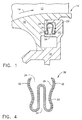
- FIG. 1 Illustrated in Figure 1 is a portion of an exemplary high pressure turbine nozzle 10 of an aircraft gas turbine engine which may be sealed in accordance with the present invention.
- the nozzle includes a plurality of circumferentially spaced apart nozzle vanes 12, only the radially inner portion thereof being illustrated, which turn and accelerate hot combustion gases 14 received from an upstream combustor (not shown).
- the vanes are integrally attached to a radially inner band 16 which is in turn mounted to an annular supporting flange 18.
- annular nested bridge seal 20 in accordance with a preferred embodiment of the invention is elastically axially compressed therebetween to reduce or prevent radial leakage therepast.
- the application of the seal 20 illustrated in Figure 1 is just one of many which may be found in the gas turbine engine as conventionally known.
- the present invention is specifically directed to improvements in the seal 20 itself which is otherwise conventionally used at any suitable location in the gas turbine engine or other apparatus.
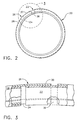
- the seal 20 is shown installed in Figure 1 and in isolation in Figure 2, and is an assembly of components including a seal ring 22 having a single circumferential split defining a corresponding circumferential gap 24, and an arcuate bridge 26 extending circumferentially across the ring gap 24 to prevent leakage thereat.
- the seal ring 22 has a serpentine transverse cross-section
- the bridge 26 has a complementary serpentine cross-section which may take any conventional form for sealing axially adjoining stator components.
- the bridge 26 includes a proximal or anchor end 28 which nests or circumferentially overlaps the seal ring 22 on one side of the gap 24.
- the bndge also includes an opposite distal or slip end 30 which also nests or circumferentially overlaps the seal ring 22 on an opposite side of the gap 24.
- the bridge 26 engages the sea! ring 22 solely in friction, with greater friction at the anchor end 28 to restrain or prevent differential circumferential movement therebetween, and less friction at the slip end 30 to permit substantially unrestrained differential circumferential movement therewith.
- the seal ring 22 itself may be configured to seal adjoining members in any conventional manner, with its circumferential gap 24 being closed by the bridge 26 to prevent leakage thereat. In this way, the bridge 26 provides a slip joint at the ring gap 24 permitting unrestrained expansion and contraction of the seal ring 22 while simultaneously sealing the gap 24.
- both the seal ring 22, and bridge 26 have complementary serpentine transverse cross-sections which are radially symmetrical, and elastically compressible thereacross in the axial direction between the adjoining inner band 16 and support flange 18 in a pocket therebetween specifically configured therefor.
- the seal ring 22 and bridge 26 each have a pair of radially extending and axially opposite reverse bends 32 which collectively define the serpentine cross-section and provide sealing surfaces for contacting the adjoining members 16,18.
- the reverse bends 32 are defined by a plurality of radially open slots or grooves 34 to effect the axially elastically compressible cross-section.
- the seal 20 is therefore axially flexible, but radially rigid in cross-section due to the serpentine configuration which has a generally hat-shape.
- the nested seal ring 22 and bridge 26 illustrated in Figure 1 are preferably formed of thin gauge sheet metal nesting together in substantially identical serpentine cross-section. Sheet metal is flexible and may be readily formed in the serpentine shape illustrated in Figure 1 using conventional equipment.
- the bridge anchor end 28 circumferentially overlaps or nests the seal ring with a greater extent than the bridge slip end 30 to frictionally secure the anchor end while allowing the slip end to slide relative to the seal ring under radial expansion and contraction.
- the bridge anchor end circumferentially overlaps the seal ring greater than a quadrant, or quarter of circle, and the bridge slip end overlaps the seal ring less than a quadrant. Since the bridge 26 is attached to the seal ring solely by friction and the nested assembly thereof, it is undesirable to have excessive friction at the slip end 30 which would prevent the substantially unrestrained expansion and contraction of the seal ring with a corresponding increase and decrease in size of the end gap 24.
- the bridge 26 is in the form of a second full ring having a second circumferential split defining a bridge gap 36, shown in more detail in Figure 3.
- the seal 20 is a two-ply construction with both the ring 22 and bridge 26 extending substantially 360°, but for the corresponding end gaps 24,36.
- the bridge gap 36 is disposed circumferentially adjacent to the ring gap 24 within a single quadrant adjacent thereto: clockwise, as shown, or counterclockwise therefrom.
- the circumferential extent of the slip end 30 is relatively short between the two gaps 24,36 to ensure substantially unrestrained slip movement between the slip end 30 and the adjoining seal ring 22.
- the bridge anchor end 28 extends over at least three quadrants and a portion of the fourth quadrant for maximizing the frictional engagement with the seal ring to prevent differential circumferential movement therebetween during operation.
- the sole circumferential differential movement between the bridge and seal ring 22 occurs at the slip end 30.
- the two-ply seal 20 may be readily manufactured using conventional equipment, with the seal ring 22 and bridge 26 being initially formed in serpentine section with their end gaps 24,36 being aligned with each other. Suitable circumferential force may then be applied to circumferentially rotate the ring and bridge relative to each other to circumferentially separate the end gaps 24,36 and complete a full ring nesting therebetween. However, since the seal 20 is loaded primarily in axial compression during operation, there is little if any circumferential force applied thereto which might change the relative circumferential position of the gaps 24,36.
- Friction alone is sufficient for maintaining assembled the seal ring 22 and its bridge 26 while also permitting substantially unrestrained radial expansion and contraction of the seal for preventing the generation of undesirable stresses therein. And, since the ring 22 and bridge 26 are simply nested together without welding, brazing, or other mechanical discontinuity, the resulting assembly is relatively simple and free of stress risers which would otherwise affect its ultimate strength.
- Figure 4 illustrates an alternate embodiment of the seal, designated 38, having a transverse cross-section in the conventional form of an E or W.
- the transverse configuration of the seal 38 illustrated in Figure 4 is slightly different than the configuration of the seal 20 illustrated in Figure 1, the same reference numerals corresponding to the same parts are used including the seal ring 22 and bridge 26 defined by different versions of the reverse bends 32 and radial slots 34.
- the seal ring 22 defines the outermost ply thereof which engages the corresponding portions of the inner band 16 and support flange 18 for effecting seals thereat.
- the corresponding bridges are provided for merely bridging the seal ring and gaps 24, and normally do not otherwise provide a seal with the adjoining band 16 and flange 18.
- the seal ring 22 and bridge 26 may have any other suitable transverse configuration for effecting sealing, with these two components being retained together by friction-only to permit substantially unrestrained differential thermal expansion and contraction of the seal ring during operation.
Claims (10)
- Dichtung (20) enthaltend:wobei die Brücke (26) allein mit Reibung an dem Dichtungsring angreift, mit einer grösseren Reibung an dem Ankerende, um eine veränderliche Umfangsbewegung zu hemmen, und weniger Reibung an dem Schleifende (30), um eine veränderliche Umfangsbewegung zu gestatten.einen Dichtungsring (22) mit einem serpentinenförmigen Querschnitt und einer hindurchführenden Umfangslücke, die einen Spalt (24) bildet,eine bogenförmige Brücke (26), die sich in Umfangsrichtung über den Spalt erstreckt und einen serpentinenförmigen Querschnitt hat, der zu dem Ring komplementär ist zum Verschachteln von einem Ankerende (28) der Brücke mit dem Dichtungsring auf dem einen Ende des Spaltes und zum Verschachteln in einem gegenüberliegenden Schleifende (30) der Brücke mit dem Dichtungsring auf einer gegenüberliegenden Seite des Spaltes, und
- Dichtung nach Anspruch 1, wobei der Dichtungsring (22) und die Brücke (26) in dem serpentinenförmigen Querschnitt symmetrisch sind und darüber elastisch kompressibel sind.
- Dichtung nach Anspruch 2, wobei der Dichtungsring (22) zwei Rückwärtsbiegungen (32) hat, die zusammen den serpentinenförmigen Querschnitt definieren und Dichtungsflächen für angrenzende Teile bilden.
- Dichtung nach Anspruch 3, wobei der Dichtungsring (22) und die Brücke aus Metallblech sind und zusammen in einem im wesentlichen identischen serpentinenförmigen Querschnitt verschachtelt sind.
- Dichtung nach Anspruch 2, wobei das Ankerende (28) der Brücke den Dichtungsring (22) in einem grösseren Ausmass in Umfangsrichtung überlappt als das Schleifende (30) der Brücke.
- Dichtung nach Anspruch 5, wobei das Ankerende (28) der Brücke den Dichtungsring (22) auf mehr als einem Quadranten in Umfangsrichtung überlappt und das Schleifende (30) der Brücke den Dichtungsring auf weniger als einem Quadranten überlappt.
- Dichtung nach Anspruch 5, wobei die Brücke (26) einen Ring mit einer Umfangslücke aufweist, die einen Brückenspalt (36) bildet.
- Dichtung nach Anspruch 7, wobei der Brückenspalt (36) in Umfangsrichtung neben dem Ringspalt (24) angeordnet ist.
- Dichtung nach Anspruch 8, wobei der Brückenspalt (36) innerhalb eines Quadranten des Ringspaltes (24) angeordnet ist.
- Dichtung nach Anspruch 9, wobei der Ring (22) und die Brücke (26) mehrere radial offene Schlitze aufweisen, um den elastisch kompressiblen Querschnitt zu bewirken.
Applications Claiming Priority (3)
| Application Number | Priority Date | Filing Date | Title |
|---|---|---|---|
| US145890 | 1998-09-02 | ||
| US09/145,890 US6237921B1 (en) | 1998-09-02 | 1998-09-02 | Nested bridge seal |
| PCT/US1999/019428 WO2000012920A1 (en) | 1998-09-02 | 1999-08-30 | Nested bridge seal |
Publications (2)
| Publication Number | Publication Date |
|---|---|
| EP1046002A1 EP1046002A1 (de) | 2000-10-25 |
| EP1046002B1 true EP1046002B1 (de) | 2004-03-17 |
Family
ID=22514997
Family Applications (1)
| Application Number | Title | Priority Date | Filing Date |
|---|---|---|---|
| EP99961510A Expired - Lifetime EP1046002B1 (de) | 1998-09-02 | 1999-08-30 | Ineinanderschiebbare brückendichtung |
Country Status (14)
| Country | Link |
|---|---|
| US (1) | US6237921B1 (de) |
| EP (1) | EP1046002B1 (de) |
| JP (1) | JP4594527B2 (de) |
| KR (1) | KR100718377B1 (de) |
| CN (1) | CN1103007C (de) |
| BR (1) | BR9906985A (de) |
| CA (1) | CA2307769C (de) |
| DE (1) | DE69915587T2 (de) |
| ES (1) | ES2216607T3 (de) |
| MY (1) | MY121444A (de) |
| NO (1) | NO320452B1 (de) |
| PL (1) | PL190652B1 (de) |
| RU (1) | RU2224155C2 (de) |
| WO (1) | WO2000012920A1 (de) |
Families Citing this family (63)
| Publication number | Priority date | Publication date | Assignee | Title |
|---|---|---|---|---|
| US6299178B1 (en) * | 1999-04-29 | 2001-10-09 | Jetseal, Inc. | Resilient seals with inflection regions and/or ply deformations |
| US6702549B2 (en) * | 2000-03-02 | 2004-03-09 | Siemens Aktiengesellschaft | Turbine installation |
| US7080513B2 (en) * | 2001-08-04 | 2006-07-25 | Siemens Aktiengesellschaft | Seal element for sealing a gap and combustion turbine having a seal element |
| GB2378486A (en) * | 2001-08-04 | 2003-02-12 | Siemens Ag | A seal element for sealing a gap and combustion turbine having such a seal element |
| US6659472B2 (en) * | 2001-12-28 | 2003-12-09 | General Electric Company | Seal for gas turbine nozzle and shroud interface |
| US6764081B2 (en) * | 2001-12-28 | 2004-07-20 | General Electric Company | Supplemental seal for the chordal hinge seals in a gas turbine and methods of installation |
| US6648333B2 (en) * | 2001-12-28 | 2003-11-18 | General Electric Company | Method of forming and installing a seal |
| US6752592B2 (en) * | 2001-12-28 | 2004-06-22 | General Electric Company | Supplemental seal for the chordal hinge seals in a gas turbine |
| US20040041351A1 (en) * | 2002-07-03 | 2004-03-04 | Alexander Beeck | Gap seal for sealing a gap between two adjacent components |
| US6883807B2 (en) | 2002-09-13 | 2005-04-26 | Seimens Westinghouse Power Corporation | Multidirectional turbine shim seal |
| US6733234B2 (en) | 2002-09-13 | 2004-05-11 | Siemens Westinghouse Power Corporation | Biased wear resistant turbine seal assembly |
| US7134287B2 (en) * | 2003-07-10 | 2006-11-14 | General Electric Company | Turbine combustor endcover assembly |
| ZA200500984B (en) * | 2004-02-12 | 2005-10-26 | Weir- Envirotech ( Pty) Ltd | Rotary pump |
| JP4727934B2 (ja) * | 2004-02-20 | 2011-07-20 | イーグル・エンジニアリング・エアロスペース株式会社 | シール装置 |
| US7207771B2 (en) * | 2004-10-15 | 2007-04-24 | Pratt & Whitney Canada Corp. | Turbine shroud segment seal |
| US7810816B1 (en) | 2005-12-13 | 2010-10-12 | Horace P. Halling | Seal |
| US7316402B2 (en) * | 2006-03-09 | 2008-01-08 | United Technologies Corporation | Segmented component seal |
| US9228533B2 (en) | 2007-11-30 | 2016-01-05 | United Technologies Corporation | Flexible seal for gas turbine engine system |
| US8459936B2 (en) | 2007-11-30 | 2013-06-11 | United Technologies Corporation | Flexible seal for gas turbine engine system |
| US8104772B2 (en) * | 2008-06-27 | 2012-01-31 | Seal Science & Technology, Llc | Gas turbine nozzle seals for 2000° F. gas containment |
| US20100072710A1 (en) * | 2008-09-22 | 2010-03-25 | General Electric Company | Gas Turbine Seal |
| US8474267B2 (en) * | 2009-03-05 | 2013-07-02 | Hamilton Sundstrand Corporation | Radial turbine engine floating ring seal |
| FR2961849B1 (fr) * | 2010-06-28 | 2013-07-05 | Snecma | Etage de turbine dans une turbomachine |
| US20120183911A1 (en) * | 2011-01-18 | 2012-07-19 | General Electric Company | Combustor and a method for repairing a combustor |
| JP5717662B2 (ja) * | 2012-01-27 | 2015-05-13 | 三菱電線工業株式会社 | 金属シール |
| CN102537350B (zh) * | 2012-02-14 | 2015-05-06 | 中国航空动力机械研究所 | 密封圈及具有该密封圈的航空发动机 |
| DE112013000584T5 (de) * | 2012-02-20 | 2014-10-23 | Borgwarner Inc. | Lagergehäuse eines Abgasturboladers |
| US9038394B2 (en) * | 2012-04-30 | 2015-05-26 | General Electric Company | Convolution seal for transition duct in turbine system |
| US9097129B2 (en) | 2012-05-31 | 2015-08-04 | United Technologies Corporation | Segmented seal with ship lap ends |
| DE102012106035A1 (de) * | 2012-07-05 | 2014-01-09 | Kraussmaffei Technologies Gmbh | Dichtung zum Einsatz in einer Strangpressvorrichtung |
| US9486833B2 (en) | 2013-02-07 | 2016-11-08 | Interface Performance Materials, Inc. | Gasket with high temperature coating |
| FR3003301B1 (fr) * | 2013-03-14 | 2018-01-05 | Safran Helicopter Engines | Anneau de turbine pour turbomachine |
| WO2015031384A1 (en) | 2013-08-30 | 2015-03-05 | United Technologies Corporation | Bifurcated sliding seal |
| US10107123B2 (en) | 2013-08-30 | 2018-10-23 | United Technologies Corporation | Sliding seal |
| US9593585B2 (en) | 2013-10-15 | 2017-03-14 | Siemens Aktiengesellschaft | Seal assembly for a gap between outlet portions of adjacent transition ducts in a gas turbine engine |
| EP3060830B1 (de) | 2013-10-24 | 2019-11-27 | United Technologies Corporation | Ringförmige kassettendichtung |
| WO2015073872A1 (en) * | 2013-11-15 | 2015-05-21 | Interface Solutions, Inc. | Sealing sleeve for slip joint |
| US9850773B2 (en) * | 2014-05-30 | 2017-12-26 | United Technologies Corporation | Dual walled seal assembly |
| US9957827B2 (en) * | 2014-10-24 | 2018-05-01 | United Technologies Corporation | Conformal seal |
| CN104481596B (zh) * | 2014-11-26 | 2016-02-10 | 哈尔滨汽轮机厂有限责任公司 | 一种被动式调节间隙的摩擦启动汽轮机汽封用汽封片 |
| CA2916710A1 (en) * | 2015-01-29 | 2016-07-29 | Rolls-Royce Corporation | Seals for gas turbine engines |
| CN104616706B (zh) * | 2015-02-05 | 2017-12-15 | 喻杰 | 一种一体化耐压壳组件 |
| US10260364B2 (en) | 2015-03-09 | 2019-04-16 | United Technologies Corporation | Sliding seal |
| US10273821B2 (en) * | 2015-09-10 | 2019-04-30 | General Electric Company | Advanced stationary sealing cooled cross-section for axial retention of ceramic matrix composite shrouds |
| US10370992B2 (en) | 2016-02-24 | 2019-08-06 | United Technologies Corporation | Seal with integral assembly clip and method of sealing |
| US9708922B1 (en) | 2016-05-23 | 2017-07-18 | United Technologies Corporation | Seal ring for gas turbine engines |
| US10202863B2 (en) | 2016-05-23 | 2019-02-12 | United Technologies Corporation | Seal ring for gas turbine engines |
| US10167957B2 (en) | 2016-05-31 | 2019-01-01 | United Technologies Corporation | 2 ply W-seal using dissimilar materials |
| US9982550B2 (en) * | 2016-06-02 | 2018-05-29 | United Technologies Corporation | Joined two ply w seal |
| US10487943B2 (en) * | 2016-07-12 | 2019-11-26 | United Technologies Corporation | Multi-ply seal ring |
| US10107398B2 (en) * | 2016-09-16 | 2018-10-23 | Ford Global Technologies, Llc | Extruded gasket side by side end cut system |
| US10385717B2 (en) * | 2016-10-12 | 2019-08-20 | United Technologies Corporation | Multi-ply seal |
| US10450883B2 (en) | 2016-10-31 | 2019-10-22 | United Technologies Corporation | W-seal shield for interrupted cavity |
| US10577977B2 (en) | 2017-02-22 | 2020-03-03 | Rolls-Royce Corporation | Turbine shroud with biased retaining ring |
| CN107091125A (zh) * | 2017-06-09 | 2017-08-25 | 中国航发湖南动力机械研究所 | 封严环、圆弧端齿联轴器、以及航空发动机 |
| DE102017116093A1 (de) * | 2017-07-18 | 2019-01-24 | Dätwyler Sealing Technologies Deutschland Gmbh | Dichtungsprofil zur Einbettung in ein Formteil aus aushärtbarem Material |
| US10392967B2 (en) | 2017-11-13 | 2019-08-27 | General Electric Company | Compliant seal component and associated method |
| WO2019108745A1 (en) * | 2017-11-30 | 2019-06-06 | Saint-Gobain Performance Plastics Corporation | Seal, assembly, and methods of using the same |
| US11359505B2 (en) * | 2019-05-04 | 2022-06-14 | Raytheon Technologies Corporation | Nesting CMC components |
| TWI817133B (zh) * | 2020-06-03 | 2023-10-01 | 美商聖高拜塑膠製品公司 | 動態金屬密封件 |
| CN112392952B (zh) * | 2020-10-29 | 2022-10-25 | 西安近代化学研究所 | 一种密封连接装置 |
| CN114087370A (zh) * | 2021-10-12 | 2022-02-25 | 中核核电运行管理有限公司 | 一种可重复使用的弹性金属自密封环及使用方法 |
| DE102022205646A1 (de) * | 2022-06-02 | 2023-12-07 | Siemens Energy Global GmbH & Co. KG | Dichtungsring mit überlappenden Dichtungsteilen und Rotoranordnung mit einem solchen |
Family Cites Families (21)
| Publication number | Priority date | Publication date | Assignee | Title |
|---|---|---|---|---|
| US499266A (en) * | 1893-06-13 | John j | ||
| US1151112A (en) | 1914-12-03 | 1915-08-24 | Virgil P Magarrell | Piston-ring. |
| US1382465A (en) | 1920-02-12 | 1921-06-21 | Bramberry Harry Morton | Metallic piston-packing |
| US1447533A (en) | 1922-05-15 | 1923-03-06 | Frank S Chopieska | Piston ring |
| US2202802A (en) * | 1936-12-14 | 1940-05-28 | William S Mason | Piston ring |
| US2761749A (en) * | 1954-05-17 | 1956-09-04 | Ramsey Corp | Oil control ring |
| US3012802A (en) * | 1958-12-04 | 1961-12-12 | Associated Spring Corp | High temperature seal |
| US3370858A (en) * | 1965-08-23 | 1968-02-27 | Gould National Batteries Inc | Piston ring assembly |
| GB1493913A (en) | 1975-06-04 | 1977-11-30 | Gen Motors Corp | Turbomachine stator interstage seal |
| US4210338A (en) * | 1978-12-28 | 1980-07-01 | Cummins Engine Company, Inc. | Piston ring assembly |
| US4218067A (en) | 1979-02-02 | 1980-08-19 | Pressure Science Incorporated | Multi-ply sealing rings |
| US4477086A (en) * | 1982-11-01 | 1984-10-16 | United Technologies Corporation | Seal ring with slidable inner element bridging circumferential gap |
| US4759555A (en) | 1985-07-25 | 1988-07-26 | Eg&G Pressure Science, Inc. | Split ring seal with slip joint |
| US4602795A (en) * | 1985-12-06 | 1986-07-29 | United Technologies Corporation | Thermally expansive slip joint for formed sheet metal seals |
| DE3642680A1 (de) * | 1986-12-13 | 1988-06-23 | Deere & Co | Vorrichtung zum verschliessen eines spaltes |
| JPH01105070A (ja) * | 1987-09-16 | 1989-04-21 | Eg & G Pressure Science Inc | スリップ継手を持つ割りリングシール |
| US5193974A (en) * | 1991-07-01 | 1993-03-16 | Bw/Ip International, Inc. | Dynamic pressure recovery seal |
| US5249814A (en) | 1992-01-31 | 1993-10-05 | Eg&G Pressure Science, Inc. | Multi-ply sealing rings and methods for manufacturing same |
| US5372476A (en) | 1993-06-18 | 1994-12-13 | General Electric Company | Turbine nozzle support assembly |
| US5630593A (en) | 1994-09-12 | 1997-05-20 | Eg&G Pressure Science, Inc. | Pressure-energized sealing rings |
| US5794941A (en) * | 1995-06-01 | 1998-08-18 | Dana Corporation | Piston ring assembly |
-
1998
- 1998-09-02 US US09/145,890 patent/US6237921B1/en not_active Expired - Lifetime
-
1999
- 1999-08-30 BR BR9906985-7A patent/BR9906985A/pt not_active IP Right Cessation
- 1999-08-30 ES ES99961510T patent/ES2216607T3/es not_active Expired - Lifetime
- 1999-08-30 CA CA002307769A patent/CA2307769C/en not_active Expired - Fee Related
- 1999-08-30 RU RU2000114172/06A patent/RU2224155C2/ru not_active IP Right Cessation
- 1999-08-30 WO PCT/US1999/019428 patent/WO2000012920A1/en active IP Right Grant
- 1999-08-30 DE DE69915587T patent/DE69915587T2/de not_active Expired - Lifetime
- 1999-08-30 CN CN99801546A patent/CN1103007C/zh not_active Expired - Fee Related
- 1999-08-30 EP EP99961510A patent/EP1046002B1/de not_active Expired - Lifetime
- 1999-08-30 PL PL99340399A patent/PL190652B1/pl not_active IP Right Cessation
- 1999-08-30 KR KR1020007004731A patent/KR100718377B1/ko not_active IP Right Cessation
- 1999-08-30 JP JP2000567868A patent/JP4594527B2/ja not_active Expired - Fee Related
- 1999-09-01 MY MYPI99003764A patent/MY121444A/en unknown
-
2000
- 2000-05-02 NO NO20002324A patent/NO320452B1/no unknown
Also Published As
| Publication number | Publication date |
|---|---|
| CN1103007C (zh) | 2003-03-12 |
| EP1046002A1 (de) | 2000-10-25 |
| CN1277660A (zh) | 2000-12-20 |
| KR100718377B1 (ko) | 2007-05-14 |
| WO2000012920A1 (en) | 2000-03-09 |
| RU2224155C2 (ru) | 2004-02-20 |
| NO320452B1 (no) | 2005-12-05 |
| MY121444A (en) | 2006-01-28 |
| ES2216607T3 (es) | 2004-10-16 |
| KR20010031673A (ko) | 2001-04-16 |
| US6237921B1 (en) | 2001-05-29 |
| JP2002523712A (ja) | 2002-07-30 |
| JP4594527B2 (ja) | 2010-12-08 |
| NO20002324L (no) | 2000-06-29 |
| BR9906985A (pt) | 2000-09-26 |
| NO20002324D0 (no) | 2000-05-02 |
| CA2307769A1 (en) | 2000-03-09 |
| DE69915587T2 (de) | 2005-01-05 |
| DE69915587D1 (de) | 2004-04-22 |
| PL340399A1 (en) | 2001-01-29 |
| PL190652B1 (pl) | 2005-12-30 |
| CA2307769C (en) | 2008-10-21 |
Similar Documents
| Publication | Publication Date | Title |
|---|---|---|
| EP1046002B1 (de) | Ineinanderschiebbare brückendichtung | |
| US20100072710A1 (en) | Gas Turbine Seal | |
| EP1045959B1 (de) | C-förmiger dichtring | |
| KR100762536B1 (ko) | 가스 터빈 | |
| KR100681560B1 (ko) | 가스 터빈 | |
| US7237388B2 (en) | Assembly comprising a gas turbine combustion chamber integrated with a high pressure turbine nozzle | |
| US8573603B2 (en) | Split ring seal with spring element | |
| JP4205421B2 (ja) | ガスタービンにおける弦ヒンジシールのための補助シール | |
| US20060082074A1 (en) | Circumferential feather seal | |
| US20040239050A1 (en) | Device for maintaining joints with sealing leaves | |
| US20060032236A1 (en) | Mounting a high pressure turbine nozzle in leaktight manner to one end of a combustion chamber in a gas turbine | |
| JP2007513281A (ja) | 燃焼器壁とノズルプラットフォームとの間の褶動ジョイント | |
| KR20030057422A (ko) | 터빈 | |
| KR20030057427A (ko) | 터빈 | |
| KR100767866B1 (ko) | 가스 터빈 | |
| JP4248871B2 (ja) | ガスタービンにおける弦ヒンジシールのための補助シール | |
| CN102022754B (zh) | 用于涡轮发动机的周向自膨胀燃烧器支撑件 | |
| JP2003227351A (ja) | ガスタービンにおける弦ヒンジシールのための補助シール | |
| MXPA00004259A (en) | Nested bridge seal |
Legal Events
| Date | Code | Title | Description |
|---|---|---|---|
| PUAI | Public reference made under article 153(3) epc to a published international application that has entered the european phase |
Free format text: ORIGINAL CODE: 0009012 |
|
| AK | Designated contracting states |
Kind code of ref document: A1 Designated state(s): AT BE CH CY DE DK ES FI FR GB GR IE IT LI LU MC NL PT SE |
|
| 17P | Request for examination filed |
Effective date: 20000911 |
|
| GRAH | Despatch of communication of intention to grant a patent |
Free format text: ORIGINAL CODE: EPIDOS IGRA |
|
| GRAS | Grant fee paid |
Free format text: ORIGINAL CODE: EPIDOSNIGR3 |
|
| GRAA | (expected) grant |
Free format text: ORIGINAL CODE: 0009210 |
|
| AK | Designated contracting states |
Kind code of ref document: B1 Designated state(s): DE ES FR GB IE IT NL SE |
|
| REG | Reference to a national code |
Ref country code: GB Ref legal event code: FG4D |
|
| REG | Reference to a national code |
Ref country code: IE Ref legal event code: FG4D |
|
| REF | Corresponds to: |
Ref document number: 69915587 Country of ref document: DE Date of ref document: 20040422 Kind code of ref document: P |
|
| REG | Reference to a national code |
Ref country code: SE Ref legal event code: TRGR |
|
| REG | Reference to a national code |
Ref country code: ES Ref legal event code: FG2A Ref document number: 2216607 Country of ref document: ES Kind code of ref document: T3 |
|
| ET | Fr: translation filed | ||
| PLBE | No opposition filed within time limit |
Free format text: ORIGINAL CODE: 0009261 |
|
| STAA | Information on the status of an ep patent application or granted ep patent |
Free format text: STATUS: NO OPPOSITION FILED WITHIN TIME LIMIT |
|
| 26N | No opposition filed |
Effective date: 20041220 |
|
| PGFP | Annual fee paid to national office [announced via postgrant information from national office to epo] |
Ref country code: IE Payment date: 20060828 Year of fee payment: 8 Ref country code: ES Payment date: 20060828 Year of fee payment: 8 |
|
| PGFP | Annual fee paid to national office [announced via postgrant information from national office to epo] |
Ref country code: SE Payment date: 20060829 Year of fee payment: 8 |
|
| EUG | Se: european patent has lapsed | ||
| PG25 | Lapsed in a contracting state [announced via postgrant information from national office to epo] |
Ref country code: SE Free format text: LAPSE BECAUSE OF NON-PAYMENT OF DUE FEES Effective date: 20070831 |
|
| REG | Reference to a national code |
Ref country code: IE Ref legal event code: MM4A |
|
| PG25 | Lapsed in a contracting state [announced via postgrant information from national office to epo] |
Ref country code: IE Free format text: LAPSE BECAUSE OF NON-PAYMENT OF DUE FEES Effective date: 20070830 |
|
| REG | Reference to a national code |
Ref country code: ES Ref legal event code: FD2A Effective date: 20070831 |
|
| PG25 | Lapsed in a contracting state [announced via postgrant information from national office to epo] |
Ref country code: ES Free format text: LAPSE BECAUSE OF NON-PAYMENT OF DUE FEES Effective date: 20070831 |
|
| REG | Reference to a national code |
Ref country code: FR Ref legal event code: PLFP Year of fee payment: 17 |
|
| PGFP | Annual fee paid to national office [announced via postgrant information from national office to epo] |
Ref country code: NL Payment date: 20150826 Year of fee payment: 17 |
|
| PGFP | Annual fee paid to national office [announced via postgrant information from national office to epo] |
Ref country code: GB Payment date: 20150827 Year of fee payment: 17 Ref country code: DE Payment date: 20150827 Year of fee payment: 17 |
|
| PGFP | Annual fee paid to national office [announced via postgrant information from national office to epo] |
Ref country code: FR Payment date: 20150817 Year of fee payment: 17 |
|
| PGFP | Annual fee paid to national office [announced via postgrant information from national office to epo] |
Ref country code: IT Payment date: 20150825 Year of fee payment: 17 |
|
| REG | Reference to a national code |
Ref country code: DE Ref legal event code: R119 Ref document number: 69915587 Country of ref document: DE |
|
| REG | Reference to a national code |
Ref country code: NL Ref legal event code: MM Effective date: 20160901 |
|
| GBPC | Gb: european patent ceased through non-payment of renewal fee |
Effective date: 20160830 |
|
| REG | Reference to a national code |
Ref country code: FR Ref legal event code: ST Effective date: 20170428 |
|
| PG25 | Lapsed in a contracting state [announced via postgrant information from national office to epo] |
Ref country code: NL Free format text: LAPSE BECAUSE OF NON-PAYMENT OF DUE FEES Effective date: 20160901 |
|
| PG25 | Lapsed in a contracting state [announced via postgrant information from national office to epo] |
Ref country code: GB Free format text: LAPSE BECAUSE OF NON-PAYMENT OF DUE FEES Effective date: 20160830 Ref country code: FR Free format text: LAPSE BECAUSE OF NON-PAYMENT OF DUE FEES Effective date: 20160831 Ref country code: DE Free format text: LAPSE BECAUSE OF NON-PAYMENT OF DUE FEES Effective date: 20170301 |
|
| PG25 | Lapsed in a contracting state [announced via postgrant information from national office to epo] |
Ref country code: IT Free format text: LAPSE BECAUSE OF NON-PAYMENT OF DUE FEES Effective date: 20160830 |