EP1046002B1 - Nested bridge seal - Google Patents
Nested bridge seal Download PDFInfo
- Publication number
- EP1046002B1 EP1046002B1 EP99961510A EP99961510A EP1046002B1 EP 1046002 B1 EP1046002 B1 EP 1046002B1 EP 99961510 A EP99961510 A EP 99961510A EP 99961510 A EP99961510 A EP 99961510A EP 1046002 B1 EP1046002 B1 EP 1046002B1
- Authority
- EP
- European Patent Office
- Prior art keywords
- bridge
- seal
- seal ring
- gap
- ring
- Prior art date
- Legal status (The legal status is an assumption and is not a legal conclusion. Google has not performed a legal analysis and makes no representation as to the accuracy of the status listed.)
- Expired - Lifetime
Links
Images
Classifications
-
- F—MECHANICAL ENGINEERING; LIGHTING; HEATING; WEAPONS; BLASTING
- F16—ENGINEERING ELEMENTS AND UNITS; GENERAL MEASURES FOR PRODUCING AND MAINTAINING EFFECTIVE FUNCTIONING OF MACHINES OR INSTALLATIONS; THERMAL INSULATION IN GENERAL
- F16J—PISTONS; CYLINDERS; SEALINGS
- F16J15/00—Sealings
- F16J15/02—Sealings between relatively-stationary surfaces
- F16J15/06—Sealings between relatively-stationary surfaces with solid packing compressed between sealing surfaces
- F16J15/08—Sealings between relatively-stationary surfaces with solid packing compressed between sealing surfaces with exclusively metal packing
-
- F—MECHANICAL ENGINEERING; LIGHTING; HEATING; WEAPONS; BLASTING
- F01—MACHINES OR ENGINES IN GENERAL; ENGINE PLANTS IN GENERAL; STEAM ENGINES
- F01D—NON-POSITIVE DISPLACEMENT MACHINES OR ENGINES, e.g. STEAM TURBINES
- F01D11/00—Preventing or minimising internal leakage of working-fluid, e.g. between stages
- F01D11/005—Sealing means between non relatively rotating elements
-
- F—MECHANICAL ENGINEERING; LIGHTING; HEATING; WEAPONS; BLASTING
- F16—ENGINEERING ELEMENTS AND UNITS; GENERAL MEASURES FOR PRODUCING AND MAINTAINING EFFECTIVE FUNCTIONING OF MACHINES OR INSTALLATIONS; THERMAL INSULATION IN GENERAL
- F16J—PISTONS; CYLINDERS; SEALINGS
- F16J15/00—Sealings
- F16J15/02—Sealings between relatively-stationary surfaces
- F16J15/06—Sealings between relatively-stationary surfaces with solid packing compressed between sealing surfaces
- F16J15/08—Sealings between relatively-stationary surfaces with solid packing compressed between sealing surfaces with exclusively metal packing
- F16J15/0887—Sealings between relatively-stationary surfaces with solid packing compressed between sealing surfaces with exclusively metal packing the sealing effect being obtained by elastic deformation of the packing
Landscapes
- Engineering & Computer Science (AREA)
- General Engineering & Computer Science (AREA)
- Mechanical Engineering (AREA)
- Gasket Seals (AREA)
- Sealing Devices (AREA)
- Braking Arrangements (AREA)
- Materials For Medical Uses (AREA)
- Refuge Islands, Traffic Blockers, Or Guard Fence (AREA)
Description
Claims (10)
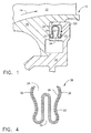
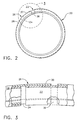
- A seal (20) comprising:a seal ring (22) having a serpentine cross-section, and a circumferential split therethrough defining a gap (24);an arcuate bridge (26) extending circumferentially across said gap, and having a serpentine cross-section being complementary with said seal ring for nesting an anchor end (28) of said bridge with said seal ring on one side of said gap, and nesting in an opposite slip end (30) of said bridge with said seal ring on an opposite side of the said gap; andsaid bridge (26) engages said seal ring solely in friction, with greater friction at said anchor end (28) to restrain differential circumferential movement, and less friction at said slip end (30) to permit differential circumferential movement.
- A seal according to claim 1 wherein said seal ring (22) and bridge (26) are symmetrical in said serpentine cross-section, and elastically compressible thereacross.
- A seal according to claim 2 wherein said seal ring (22) includes a pair of reverse bends (32) collectively defining said serpentine cross-section and providing sealing surfaces for adjoining members.
- A seal according to claim 3 wherein said seal ring (22) and bridge are sheet metal nesting together in substantially identical serpentine cross-section.
- A seal according to claim 2 wherein said bridge anchor end (28) circumferentially overlaps said seal ring (22) with a greater extent than said bridge slip end (30).
- A seal according to claim 5 wherein said bridge anchor end (28) circumferentially overlaps said seal ring (22) greater than a quadrant, and said bridge slip end (30) overlaps said seal ring less than a quadrant.
- A seal according to claim 5 wherein said bridge (26) comprises a ring having a circumferential split defining a bridge gap (36).
- A seal according to claim 7 wherein said bridge gap (36) is disposed circumferentially adjacent to said ring gap (24).
- A seal according to claim 8 wherein said bridge gap (36) is disposed within a quadrant of said ring gap (24).
- A seal according to claim 9 wherein said seal ring (22) and bridge (26) include a plurality of radially open slots to effect said elastically compressible cross-section.
Applications Claiming Priority (3)
| Application Number | Priority Date | Filing Date | Title |
|---|---|---|---|
| US09/145,890 US6237921B1 (en) | 1998-09-02 | 1998-09-02 | Nested bridge seal |
| US145890 | 1998-09-02 | ||
| PCT/US1999/019428 WO2000012920A1 (en) | 1998-09-02 | 1999-08-30 | Nested bridge seal |
Publications (2)
| Publication Number | Publication Date |
|---|---|
| EP1046002A1 EP1046002A1 (en) | 2000-10-25 |
| EP1046002B1 true EP1046002B1 (en) | 2004-03-17 |
Family
ID=22514997
Family Applications (1)
| Application Number | Title | Priority Date | Filing Date |
|---|---|---|---|
| EP99961510A Expired - Lifetime EP1046002B1 (en) | 1998-09-02 | 1999-08-30 | Nested bridge seal |
Country Status (14)
| Country | Link |
|---|---|
| US (1) | US6237921B1 (en) |
| EP (1) | EP1046002B1 (en) |
| JP (1) | JP4594527B2 (en) |
| KR (1) | KR100718377B1 (en) |
| CN (1) | CN1103007C (en) |
| BR (1) | BR9906985A (en) |
| CA (1) | CA2307769C (en) |
| DE (1) | DE69915587T2 (en) |
| ES (1) | ES2216607T3 (en) |
| MY (1) | MY121444A (en) |
| NO (1) | NO320452B1 (en) |
| PL (1) | PL190652B1 (en) |
| RU (1) | RU2224155C2 (en) |
| WO (1) | WO2000012920A1 (en) |
Families Citing this family (63)
| Publication number | Priority date | Publication date | Assignee | Title |
|---|---|---|---|---|
| US6299178B1 (en) * | 1999-04-29 | 2001-10-09 | Jetseal, Inc. | Resilient seals with inflection regions and/or ply deformations |
| US6702549B2 (en) * | 2000-03-02 | 2004-03-09 | Siemens Aktiengesellschaft | Turbine installation |
| US7080513B2 (en) * | 2001-08-04 | 2006-07-25 | Siemens Aktiengesellschaft | Seal element for sealing a gap and combustion turbine having a seal element |
| GB2378486A (en) * | 2001-08-04 | 2003-02-12 | Siemens Ag | A seal element for sealing a gap and combustion turbine having such a seal element |
| US6648333B2 (en) | 2001-12-28 | 2003-11-18 | General Electric Company | Method of forming and installing a seal |
| US6764081B2 (en) | 2001-12-28 | 2004-07-20 | General Electric Company | Supplemental seal for the chordal hinge seals in a gas turbine and methods of installation |
| US6659472B2 (en) * | 2001-12-28 | 2003-12-09 | General Electric Company | Seal for gas turbine nozzle and shroud interface |
| US6752592B2 (en) * | 2001-12-28 | 2004-06-22 | General Electric Company | Supplemental seal for the chordal hinge seals in a gas turbine |
| US20040041351A1 (en) * | 2002-07-03 | 2004-03-04 | Alexander Beeck | Gap seal for sealing a gap between two adjacent components |
| US6733234B2 (en) | 2002-09-13 | 2004-05-11 | Siemens Westinghouse Power Corporation | Biased wear resistant turbine seal assembly |
| US6883807B2 (en) | 2002-09-13 | 2005-04-26 | Seimens Westinghouse Power Corporation | Multidirectional turbine shim seal |
| US7134287B2 (en) * | 2003-07-10 | 2006-11-14 | General Electric Company | Turbine combustor endcover assembly |
| ZA200500984B (en) * | 2004-02-12 | 2005-10-26 | Weir- Envirotech ( Pty) Ltd | Rotary pump |
| JP4727934B2 (en) * | 2004-02-20 | 2011-07-20 | イーグル・エンジニアリング・エアロスペース株式会社 | Sealing device |
| US7207771B2 (en) * | 2004-10-15 | 2007-04-24 | Pratt & Whitney Canada Corp. | Turbine shroud segment seal |
| US7810816B1 (en) * | 2005-12-13 | 2010-10-12 | Horace P. Halling | Seal |
| US7316402B2 (en) * | 2006-03-09 | 2008-01-08 | United Technologies Corporation | Segmented component seal |
| US8459936B2 (en) | 2007-11-30 | 2013-06-11 | United Technologies Corporation | Flexible seal for gas turbine engine system |
| US9228533B2 (en) | 2007-11-30 | 2016-01-05 | United Technologies Corporation | Flexible seal for gas turbine engine system |
| US8104772B2 (en) * | 2008-06-27 | 2012-01-31 | Seal Science & Technology, Llc | Gas turbine nozzle seals for 2000° F. gas containment |
| US20100072710A1 (en) * | 2008-09-22 | 2010-03-25 | General Electric Company | Gas Turbine Seal |
| US8474267B2 (en) * | 2009-03-05 | 2013-07-02 | Hamilton Sundstrand Corporation | Radial turbine engine floating ring seal |
| FR2961849B1 (en) * | 2010-06-28 | 2013-07-05 | Snecma | TURBINE STAGE IN A TURBOMACHINE |
| US20120183911A1 (en) * | 2011-01-18 | 2012-07-19 | General Electric Company | Combustor and a method for repairing a combustor |
| JP5717662B2 (en) * | 2012-01-27 | 2015-05-13 | 三菱電線工業株式会社 | Metal seal |
| CN102537350B (en) * | 2012-02-14 | 2015-05-06 | 中国航空动力机械研究所 | Sealing ring and aircraft engine with same |
| WO2013126231A1 (en) * | 2012-02-20 | 2013-08-29 | Borgwarner Inc. | Bearing housing of an exhaust-gas turbocharger |
| US9038394B2 (en) * | 2012-04-30 | 2015-05-26 | General Electric Company | Convolution seal for transition duct in turbine system |
| US9097129B2 (en) | 2012-05-31 | 2015-08-04 | United Technologies Corporation | Segmented seal with ship lap ends |
| DE102012106035A1 (en) * | 2012-07-05 | 2014-01-09 | Kraussmaffei Technologies Gmbh | Seal for use in an extrusion device |
| EP2954096A1 (en) | 2013-02-07 | 2015-12-16 | Interface Performance Materials, Inc. | Gasket with high temperature coating |
| FR3003301B1 (en) | 2013-03-14 | 2018-01-05 | Safran Helicopter Engines | TURBINE RING FOR TURBOMACHINE |
| EP3039316B1 (en) * | 2013-08-30 | 2020-10-21 | United Technologies Corporation | Sliding seal |
| WO2015031384A1 (en) | 2013-08-30 | 2015-03-05 | United Technologies Corporation | Bifurcated sliding seal |
| US9593585B2 (en) | 2013-10-15 | 2017-03-14 | Siemens Aktiengesellschaft | Seal assembly for a gap between outlet portions of adjacent transition ducts in a gas turbine engine |
| WO2015061108A1 (en) * | 2013-10-24 | 2015-04-30 | United Technologies Corporation | Annular cartridge seal |
| WO2015073872A1 (en) * | 2013-11-15 | 2015-05-21 | Interface Solutions, Inc. | Sealing sleeve for slip joint |
| US9850773B2 (en) * | 2014-05-30 | 2017-12-26 | United Technologies Corporation | Dual walled seal assembly |
| US9957827B2 (en) * | 2014-10-24 | 2018-05-01 | United Technologies Corporation | Conformal seal |
| CN104481596B (en) * | 2014-11-26 | 2016-02-10 | 哈尔滨汽轮机厂有限责任公司 | A kind of friction of passive modulation internode gap starts turbine steam seal labyrinth strip |
| CA2916710A1 (en) * | 2015-01-29 | 2016-07-29 | Rolls-Royce Corporation | Seals for gas turbine engines |
| CN104616706B (en) * | 2015-02-05 | 2017-12-15 | 喻杰 | A kind of pressure-resistant shell component of integration |
| US10260364B2 (en) | 2015-03-09 | 2019-04-16 | United Technologies Corporation | Sliding seal |
| US10273821B2 (en) | 2015-09-10 | 2019-04-30 | General Electric Company | Advanced stationary sealing cooled cross-section for axial retention of ceramic matrix composite shrouds |
| US10370992B2 (en) | 2016-02-24 | 2019-08-06 | United Technologies Corporation | Seal with integral assembly clip and method of sealing |
| US9708922B1 (en) | 2016-05-23 | 2017-07-18 | United Technologies Corporation | Seal ring for gas turbine engines |
| US10202863B2 (en) | 2016-05-23 | 2019-02-12 | United Technologies Corporation | Seal ring for gas turbine engines |
| US10167957B2 (en) | 2016-05-31 | 2019-01-01 | United Technologies Corporation | 2 ply W-seal using dissimilar materials |
| US9982550B2 (en) * | 2016-06-02 | 2018-05-29 | United Technologies Corporation | Joined two ply w seal |
| US10487943B2 (en) * | 2016-07-12 | 2019-11-26 | United Technologies Corporation | Multi-ply seal ring |
| US10107398B2 (en) * | 2016-09-16 | 2018-10-23 | Ford Global Technologies, Llc | Extruded gasket side by side end cut system |
| US10385717B2 (en) * | 2016-10-12 | 2019-08-20 | United Technologies Corporation | Multi-ply seal |
| US10450883B2 (en) | 2016-10-31 | 2019-10-22 | United Technologies Corporation | W-seal shield for interrupted cavity |
| US10577977B2 (en) | 2017-02-22 | 2020-03-03 | Rolls-Royce Corporation | Turbine shroud with biased retaining ring |
| CN107091125A (en) * | 2017-06-09 | 2017-08-25 | 中国航发湖南动力机械研究所 | Obturage ring, arc end tooth coupling and aero-engine |
| DE102017116093A1 (en) * | 2017-07-18 | 2019-01-24 | Dätwyler Sealing Technologies Deutschland Gmbh | Sealing profile for embedding in a molded part of hardenable material |
| US10392967B2 (en) | 2017-11-13 | 2019-08-27 | General Electric Company | Compliant seal component and associated method |
| CA3083964C (en) * | 2017-11-30 | 2023-12-12 | Saint-Gobain Performance Plastics Corporation | Seal, assembly, and methods of using the same |
| US11359505B2 (en) * | 2019-05-04 | 2022-06-14 | Raytheon Technologies Corporation | Nesting CMC components |
| KR20230048257A (en) * | 2020-06-03 | 2023-04-11 | 생-고뱅 퍼포먼스 플라스틱스 코포레이션 | dynamic metal seal |
| CN112392952B (en) * | 2020-10-29 | 2022-10-25 | 西安近代化学研究所 | Sealing connection device |
| CN114087370A (en) * | 2021-10-12 | 2022-02-25 | 中核核电运行管理有限公司 | Reusable elastic metal self-sealing ring and use method thereof |
| DE102022205646A1 (en) * | 2022-06-02 | 2023-12-07 | Siemens Energy Global GmbH & Co. KG | Sealing ring with overlapping sealing parts and rotor arrangement with such |
Family Cites Families (21)
| Publication number | Priority date | Publication date | Assignee | Title |
|---|---|---|---|---|
| US499266A (en) * | 1893-06-13 | John j | ||
| US1151112A (en) | 1914-12-03 | 1915-08-24 | Virgil P Magarrell | Piston-ring. |
| US1382465A (en) | 1920-02-12 | 1921-06-21 | Bramberry Harry Morton | Metallic piston-packing |
| US1447533A (en) | 1922-05-15 | 1923-03-06 | Frank S Chopieska | Piston ring |
| US2202802A (en) * | 1936-12-14 | 1940-05-28 | William S Mason | Piston ring |
| US2761749A (en) * | 1954-05-17 | 1956-09-04 | Ramsey Corp | Oil control ring |
| US3012802A (en) * | 1958-12-04 | 1961-12-12 | Associated Spring Corp | High temperature seal |
| US3370858A (en) * | 1965-08-23 | 1968-02-27 | Gould National Batteries Inc | Piston ring assembly |
| GB1493913A (en) | 1975-06-04 | 1977-11-30 | Gen Motors Corp | Turbomachine stator interstage seal |
| US4210338A (en) * | 1978-12-28 | 1980-07-01 | Cummins Engine Company, Inc. | Piston ring assembly |
| US4218067A (en) | 1979-02-02 | 1980-08-19 | Pressure Science Incorporated | Multi-ply sealing rings |
| US4477086A (en) * | 1982-11-01 | 1984-10-16 | United Technologies Corporation | Seal ring with slidable inner element bridging circumferential gap |
| US4759555A (en) | 1985-07-25 | 1988-07-26 | Eg&G Pressure Science, Inc. | Split ring seal with slip joint |
| US4602795A (en) | 1985-12-06 | 1986-07-29 | United Technologies Corporation | Thermally expansive slip joint for formed sheet metal seals |
| DE3642680A1 (en) * | 1986-12-13 | 1988-06-23 | Deere & Co | DEVICE FOR CLOSING A GAP |
| JPH01105070A (en) * | 1987-09-16 | 1989-04-21 | Eg & G Pressure Science Inc | Split ring seal with slip joint |
| US5193974A (en) * | 1991-07-01 | 1993-03-16 | Bw/Ip International, Inc. | Dynamic pressure recovery seal |
| US5249814A (en) | 1992-01-31 | 1993-10-05 | Eg&G Pressure Science, Inc. | Multi-ply sealing rings and methods for manufacturing same |
| US5372476A (en) | 1993-06-18 | 1994-12-13 | General Electric Company | Turbine nozzle support assembly |
| US5630593A (en) | 1994-09-12 | 1997-05-20 | Eg&G Pressure Science, Inc. | Pressure-energized sealing rings |
| US5794941A (en) * | 1995-06-01 | 1998-08-18 | Dana Corporation | Piston ring assembly |
-
1998
- 1998-09-02 US US09/145,890 patent/US6237921B1/en not_active Expired - Lifetime
-
1999
- 1999-08-30 KR KR1020007004731A patent/KR100718377B1/en not_active IP Right Cessation
- 1999-08-30 JP JP2000567868A patent/JP4594527B2/en not_active Expired - Fee Related
- 1999-08-30 EP EP99961510A patent/EP1046002B1/en not_active Expired - Lifetime
- 1999-08-30 CN CN99801546A patent/CN1103007C/en not_active Expired - Fee Related
- 1999-08-30 WO PCT/US1999/019428 patent/WO2000012920A1/en active IP Right Grant
- 1999-08-30 CA CA002307769A patent/CA2307769C/en not_active Expired - Fee Related
- 1999-08-30 BR BR9906985-7A patent/BR9906985A/en not_active IP Right Cessation
- 1999-08-30 DE DE69915587T patent/DE69915587T2/en not_active Expired - Lifetime
- 1999-08-30 PL PL99340399A patent/PL190652B1/en not_active IP Right Cessation
- 1999-08-30 RU RU2000114172/06A patent/RU2224155C2/en not_active IP Right Cessation
- 1999-08-30 ES ES99961510T patent/ES2216607T3/en not_active Expired - Lifetime
- 1999-09-01 MY MYPI99003764A patent/MY121444A/en unknown
-
2000
- 2000-05-02 NO NO20002324A patent/NO320452B1/en unknown
Also Published As
| Publication number | Publication date |
|---|---|
| RU2224155C2 (en) | 2004-02-20 |
| JP4594527B2 (en) | 2010-12-08 |
| NO320452B1 (en) | 2005-12-05 |
| BR9906985A (en) | 2000-09-26 |
| CN1103007C (en) | 2003-03-12 |
| ES2216607T3 (en) | 2004-10-16 |
| CA2307769A1 (en) | 2000-03-09 |
| NO20002324D0 (en) | 2000-05-02 |
| EP1046002A1 (en) | 2000-10-25 |
| DE69915587T2 (en) | 2005-01-05 |
| PL340399A1 (en) | 2001-01-29 |
| US6237921B1 (en) | 2001-05-29 |
| CA2307769C (en) | 2008-10-21 |
| CN1277660A (en) | 2000-12-20 |
| PL190652B1 (en) | 2005-12-30 |
| JP2002523712A (en) | 2002-07-30 |
| KR20010031673A (en) | 2001-04-16 |
| NO20002324L (en) | 2000-06-29 |
| WO2000012920A1 (en) | 2000-03-09 |
| DE69915587D1 (en) | 2004-04-22 |
| MY121444A (en) | 2006-01-28 |
| KR100718377B1 (en) | 2007-05-14 |
Similar Documents
| Publication | Publication Date | Title |
|---|---|---|
| EP1046002B1 (en) | Nested bridge seal | |
| US20100072710A1 (en) | Gas Turbine Seal | |
| EP1045959B1 (en) | C-shaped ring seal | |
| KR100762536B1 (en) | Supplemental seal for the chordal hinge seals in a gas turbine | |
| KR100681560B1 (en) | Seal for gas turbine nozzle and shroud interface | |
| US7237388B2 (en) | Assembly comprising a gas turbine combustion chamber integrated with a high pressure turbine nozzle | |
| US8573603B2 (en) | Split ring seal with spring element | |
| US7237387B2 (en) | Mounting a high pressure turbine nozzle in leaktight manner to one end of a combustion chamber in a gas turbine | |
| US20060082074A1 (en) | Circumferential feather seal | |
| US20040239050A1 (en) | Device for maintaining joints with sealing leaves | |
| JP2007513281A (en) | Peristaltic joint between combustor wall and nozzle platform | |
| KR20030057415A (en) | Supplemental seal for the chordal hinge seals in a gas turbine | |
| KR20030057422A (en) | Supplemental seal for the chordal hinge seal in a gas turbine | |
| KR20030057427A (en) | Supplemental seal for the chordal hinge seal in a gas turbine | |
| KR100767866B1 (en) | Supplemental seal for the chordal hinge seals in a gas turbine | |
| JP4248871B2 (en) | Auxiliary seal for string hinge seal in gas turbine | |
| CN102022754B (en) | Circumferentially self expanding combustor support for a turbine engine | |
| JP2003227351A (en) | Auxiliary seal for sealing chord hinge in gas turbine | |
| MXPA00004259A (en) | Nested bridge seal |
Legal Events
| Date | Code | Title | Description |
|---|---|---|---|
| PUAI | Public reference made under article 153(3) epc to a published international application that has entered the european phase |
Free format text: ORIGINAL CODE: 0009012 |
|
| AK | Designated contracting states |
Kind code of ref document: A1 Designated state(s): AT BE CH CY DE DK ES FI FR GB GR IE IT LI LU MC NL PT SE |
|
| 17P | Request for examination filed |
Effective date: 20000911 |
|
| GRAH | Despatch of communication of intention to grant a patent |
Free format text: ORIGINAL CODE: EPIDOS IGRA |
|
| GRAS | Grant fee paid |
Free format text: ORIGINAL CODE: EPIDOSNIGR3 |
|
| GRAA | (expected) grant |
Free format text: ORIGINAL CODE: 0009210 |
|
| AK | Designated contracting states |
Kind code of ref document: B1 Designated state(s): DE ES FR GB IE IT NL SE |
|
| REG | Reference to a national code |
Ref country code: GB Ref legal event code: FG4D |
|
| REG | Reference to a national code |
Ref country code: IE Ref legal event code: FG4D |
|
| REF | Corresponds to: |
Ref document number: 69915587 Country of ref document: DE Date of ref document: 20040422 Kind code of ref document: P |
|
| REG | Reference to a national code |
Ref country code: SE Ref legal event code: TRGR |
|
| REG | Reference to a national code |
Ref country code: ES Ref legal event code: FG2A Ref document number: 2216607 Country of ref document: ES Kind code of ref document: T3 |
|
| ET | Fr: translation filed | ||
| PLBE | No opposition filed within time limit |
Free format text: ORIGINAL CODE: 0009261 |
|
| STAA | Information on the status of an ep patent application or granted ep patent |
Free format text: STATUS: NO OPPOSITION FILED WITHIN TIME LIMIT |
|
| 26N | No opposition filed |
Effective date: 20041220 |
|
| PGFP | Annual fee paid to national office [announced via postgrant information from national office to epo] |
Ref country code: IE Payment date: 20060828 Year of fee payment: 8 Ref country code: ES Payment date: 20060828 Year of fee payment: 8 |
|
| PGFP | Annual fee paid to national office [announced via postgrant information from national office to epo] |
Ref country code: SE Payment date: 20060829 Year of fee payment: 8 |
|
| EUG | Se: european patent has lapsed | ||
| PG25 | Lapsed in a contracting state [announced via postgrant information from national office to epo] |
Ref country code: SE Free format text: LAPSE BECAUSE OF NON-PAYMENT OF DUE FEES Effective date: 20070831 |
|
| REG | Reference to a national code |
Ref country code: IE Ref legal event code: MM4A |
|
| PG25 | Lapsed in a contracting state [announced via postgrant information from national office to epo] |
Ref country code: IE Free format text: LAPSE BECAUSE OF NON-PAYMENT OF DUE FEES Effective date: 20070830 |
|
| REG | Reference to a national code |
Ref country code: ES Ref legal event code: FD2A Effective date: 20070831 |
|
| PG25 | Lapsed in a contracting state [announced via postgrant information from national office to epo] |
Ref country code: ES Free format text: LAPSE BECAUSE OF NON-PAYMENT OF DUE FEES Effective date: 20070831 |
|
| REG | Reference to a national code |
Ref country code: FR Ref legal event code: PLFP Year of fee payment: 17 |
|
| PGFP | Annual fee paid to national office [announced via postgrant information from national office to epo] |
Ref country code: NL Payment date: 20150826 Year of fee payment: 17 |
|
| PGFP | Annual fee paid to national office [announced via postgrant information from national office to epo] |
Ref country code: GB Payment date: 20150827 Year of fee payment: 17 Ref country code: DE Payment date: 20150827 Year of fee payment: 17 |
|
| PGFP | Annual fee paid to national office [announced via postgrant information from national office to epo] |
Ref country code: FR Payment date: 20150817 Year of fee payment: 17 |
|
| PGFP | Annual fee paid to national office [announced via postgrant information from national office to epo] |
Ref country code: IT Payment date: 20150825 Year of fee payment: 17 |
|
| REG | Reference to a national code |
Ref country code: DE Ref legal event code: R119 Ref document number: 69915587 Country of ref document: DE |
|
| REG | Reference to a national code |
Ref country code: NL Ref legal event code: MM Effective date: 20160901 |
|
| GBPC | Gb: european patent ceased through non-payment of renewal fee |
Effective date: 20160830 |
|
| REG | Reference to a national code |
Ref country code: FR Ref legal event code: ST Effective date: 20170428 |
|
| PG25 | Lapsed in a contracting state [announced via postgrant information from national office to epo] |
Ref country code: NL Free format text: LAPSE BECAUSE OF NON-PAYMENT OF DUE FEES Effective date: 20160901 |
|
| PG25 | Lapsed in a contracting state [announced via postgrant information from national office to epo] |
Ref country code: GB Free format text: LAPSE BECAUSE OF NON-PAYMENT OF DUE FEES Effective date: 20160830 Ref country code: FR Free format text: LAPSE BECAUSE OF NON-PAYMENT OF DUE FEES Effective date: 20160831 Ref country code: DE Free format text: LAPSE BECAUSE OF NON-PAYMENT OF DUE FEES Effective date: 20170301 |
|
| PG25 | Lapsed in a contracting state [announced via postgrant information from national office to epo] |
Ref country code: IT Free format text: LAPSE BECAUSE OF NON-PAYMENT OF DUE FEES Effective date: 20160830 |