EP1045583A2 - Anlage und Verfahren zur Bearbeitung von Informationen, und damit ausgestattetes Medium - Google Patents
Anlage und Verfahren zur Bearbeitung von Informationen, und damit ausgestattetes Medium Download PDFInfo
- Publication number
- EP1045583A2 EP1045583A2 EP00303132A EP00303132A EP1045583A2 EP 1045583 A2 EP1045583 A2 EP 1045583A2 EP 00303132 A EP00303132 A EP 00303132A EP 00303132 A EP00303132 A EP 00303132A EP 1045583 A2 EP1045583 A2 EP 1045583A2
- Authority
- EP
- European Patent Office
- Prior art keywords
- bus
- information processing
- processing apparatus
- address
- buses
- Prior art date
- Legal status (The legal status is an assumption and is not a legal conclusion. Google has not performed a legal analysis and makes no representation as to the accuracy of the status listed.)
- Withdrawn
Links
Images






Classifications
-
- H—ELECTRICITY
- H04—ELECTRIC COMMUNICATION TECHNIQUE
- H04N—PICTORIAL COMMUNICATION, e.g. TELEVISION
- H04N5/00—Details of television systems
- H04N5/76—Television signal recording
- H04N5/765—Interface circuits between an apparatus for recording and another apparatus
-
- H—ELECTRICITY
- H04—ELECTRIC COMMUNICATION TECHNIQUE
- H04N—PICTORIAL COMMUNICATION, e.g. TELEVISION
- H04N5/00—Details of television systems
- H04N5/76—Television signal recording
- H04N5/765—Interface circuits between an apparatus for recording and another apparatus
- H04N5/775—Interface circuits between an apparatus for recording and another apparatus between a recording apparatus and a television receiver
Definitions
- the present invention relates to information processing apparatuses and methods, and to media provided therewith, and in particular, to an information processing apparatus and method in which, when information processing apparatuses are connected by a plurality of buses, each of the information processing apparatuses is set to function securely, and to a medium used with the information processing apparatus and method.
- a bus for connecting a plurality of electronic apparatuses has come into domestic use.
- a bus of this type is an AV link defined as EN-50157 in the European Committee for Electrotechnical Standardization.
- the AV link is used to transmit and receive analog audiovisual (AV) signals or digital data.
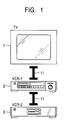
- Fig. 1 shows that a plurality of electronic apparatuses are connected by AV links of the above-described type.
- a television receiver 1, a video cassette recorder 2, and a video cassette recorder 3 are connected by AV links 11.
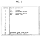
- the positions at which electronic apparatuses are connected are predetermined. Specifically, as shown in Fig. 2, a television receiver (indicated by “TV”) is treated as a highest position unit, and its address is "0".
- a video cassette recorder indicated by "VCR”
- a satellite tuner indicated by "SAT”
- the video cassette recorder be connected so as to be higher than the satellite tuner, in other words, so as to be closer to the television receiver.
- VCR-1 a (highest) video cassette recorder closest to the television receiver
- VCR-2 a video cassette recorder farthest from the television receiver
- the television receiver 1 is treated as "TV” having the highest address "0”
- the video cassette recorder 2 is treated as "VCR-1" having the second highest address "1”
- the video cassette recorder 3 is treated as "VTR-2" having the lowest address 2 on the AV links 11.
- the AV links 11 cannot be used to transmit and receive digital AV data.
- IEEE (Institute of Electrical and Electronic Engineers) 1394 high-speed serial buses which have come into widespread use, can be used also to transmit and receive digital AV data. However, they cannot be used to transmit and receive analog AV signals.
- Television receivers which are most widely used, can receive analog AV signals transmitted via a bus and can display outputs. A small number of television receivers can receive and display supplied digital AV data.
- Video cassette recorders include a type that can transmit and receive only analog AV signals and another type that can transmit and receive both analog AV signals and digital AV data.
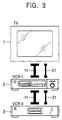
- electronic apparatuses in order for each electronic apparatus to transmit and receive both analog and digital signals, for example, electronic apparatuses must be connected not only by AV links 11 but also by IEEE 1394 buses 21, as shown in Fig. 3.
- node IDs are assigned to electronic apparatuses connected to the IEEE 1394 buses 21.
- Each node ID is represented by a 2-byte value.
- each electronic apparatus transmits and receives data via the IEEE 1394 bus, it describes a node ID assigned to an electronic apparatus that receives the data, as a destination ID of a packet including data to be transmitted, and describes a node ID assigned to itself as a source ID representing the ID of a transmitter.
- the digital signals are transferred to the television receiver 1 via the IEEE 1394 bus 21.
- the television receiver 1 uses the AV link 11 to request the video cassette recorder 2 ("VCR-1" having address “1” on the AV links 11) to perform reading, and receives the digital AV signals, it can know that the video cassette recorder 2 is "VCR-1" having address "1” on the AV links 11 and the video cassette recorder 3 is "VCR-2" having address 2 on the AV links 11.
- the television receiver 1 can know that the video cassette recorder 2 having a predetermined node ID and the video cassette recorder 3 having a predetermined node ID are connected to the television receiver 1 by the IEEE 1394 buses 21, it cannot find a node ID corresponding to "VCR-1" having address "1" on the AV links 11. Therefore, when the digital AV signals are supplied to the television receiver 1 via the IEEE 1394 buses, it is impossible for the television receiver 1 to find which node ID (as a source ID) representing a packet whose data are to be captured should be selected because the video cassette recorder 2 having the predetermined ID may output digital AV signals to the IEEE 1394 buses 21 and also the video cassette recorder 3 having the predetermined ID may transfer digital AV signals to the IEEE 1394 buses 21.
- the present invention alleviates the above problem by providing an information processing apparatus and method in which the correspondence between addresses assigned to different buses is recognized, and a medium used therewith.
- an information processing apparatus is provided that is connectable to another information processing apparatus by at least two buses.
- the information processing apparatus includes: a holding unit for holding the address of a first bus of the buses, and the address of a second bus of the buses; an inquiry unit for using the first bus to query the other information processing apparatus about the address of the second bus; and a response unit for, when the other information processing apparatus uses the first bus to query the response unit about the address of the second bus, responding to the other information processing apparatus by sending the stored address of the second bus.
- the first bus is an IEEE 1394 high-speed serial bus; and the second bus is an AV link.
- an information processing method for an information processing apparatus connectable to another information processing apparatus by at least two buses.
- the information processing method includes the steps of: holding the address of a first bus of the buses and the address of a second bus of the buses; querying the other information processing apparatus about the address of the second bus by using the first bus; and responding, when the other information processing apparatus uses the first bus to inquire about the address of the second bus, to the other information processing apparatus by sending the stored address of the second bus.
- a medium for controlling an information processing apparatus to execute a program, in which the information processing apparatus is connected to another information processing apparatus by at least two buses.
- the program executes the steps of: holding the address of a first bus of the buses and the address of a second bus of the buses; querying the other information processing apparatus about the address of the second bus by using the first bus; and responding, when the other information processing apparatus uses the first bus to inquire about the address of the second bus, to the other information processing apparatus by sending the stored address of the second bus.
- an information processing apparatus is provided that is connectable to another information processing apparatus by at least two buses.
- the information processing apparatus includes: a declaration unit for using a first bus of the buses to declare, on the other information processing apparatus, the address of a second bus of the buses; and a holding unit which, when receiving the declaration of the address of the second bus from the other information processing apparatus via the first bus, extracts the address of the first bus held in the other information processing apparatus from the declaration, and which holds the extracted address of the first bus so as to correspond to the address of the second bus held in the other information processing apparatus.
- the first bus is an AV link and the second bus is an IEEE 1394 high-speed serial bus.
- an information processing method for an information processing apparatus connectable to another information processing apparatus by at least two buses.
- the information processing method includes: a declaration step for using a first bus of the buses to declare, on the other information processing apparatus, the address of a second bus of the buses; and a holding step which, when receiving the declaration of the address of the second bus from the other information processing apparatus via the first bus, extracts the address of the first bus held in the other information processing apparatus from the declaration, and which holds the extracted address of the first bus so as to correspond to the address of the second bus held in the other information processing apparatus.
- a medium for controlling an information processing apparatus to execute a program, in which the information processing apparatus is connectable to another information processing apparatus by at least two buses.
- the program executes: a declaration step for using a first bus of the buses to declare, on the other information processing apparatus, the address of a second bus of the buses; and a holding step which, when receiving the declaration of the address of the second bus from the other information processing apparatus via the first bus, extracts the address of the first bus held in the other information processing apparatus from the declaration, and which holds the extracted address of the first bus so as to correspond to the address of the second bus held in the other information processing apparatus.
- a first bus is used to query the address of a second bus, and an information processing apparatus that receives the inquiry responds by sending the address of the second bus held in the information processing apparatus. This correlates the address of the first bus with the address of the second bus.
- a first bus is used to declare the address of a second bus, and an information processing apparatus that receives the declaration extracts the address of the first bus and holds the extracted address so as to be correlated with the address of the second bus. This can establish correspondence among the addresses of different buses.
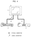
- a television receiver 1 and video cassette recorders 2 and 3 are connected by AV links 11 and an IEEE 1394 bus 21, similar to the example shown in Fig. 3.
- the television receiver 1 is "TV” having the address "0”
- the video cassette recorder 2 is "VCR-1” having the address "1”
- the video cassette recorder 3 is "VCR-2" having the address "2”. It is assumed that, when the IEEE 1394 bus is reset, the node ID "NID1" is assigned to the television receiver 1, the node ID "NID2" is assigned to the video cassette recorder 2, and the node ID "NID3" is assigned to the video cassette recorder 3.
- a node unique ID is assigned as an unchangeable ID proper to each electronic apparatus.
- "NUID1”, "NUID2”, and "NUID3" are assigned as unique IDs to the television receiver 1, the video cassette recorder 2, and the video cassette recorder 3, respectively.
- An interface (indicated by "I/F") 31 in the television receiver 1 performs interface processing on digital AV data input via the IEEE 1394 bus 21 in accordance with instructions from a controller 36, and outputs the processed data to an MPEG (moving picture expert group) decoder 32.
- the MPEG decoder 32 decodes the input AV data using the MPEG standard, and outputs the decoded data to a switch circuit 33.
- An interface 35 performs interface processing on the input analog AV signals, and outputs the processed signals to the switch circuit 33.
- the controller 36 monitors the outputs from the interface 31 and the interface 35. In accordance with a result of the monitoring, the controller 36 controls the switch circuit 33, thereby selecting and outputting either the output from the MPEG decoder 32 or the output from the interface 35 to a display 34.
- An interface 41-1 in the video cassette recorder 2 performs interface processing on digital AV data transmitted to and received from the IEEE 1394 bus 21.
- a D-VHS (trademark) processor 42-1 converts MPEG-encoded digital AV data input from the interface 41-1 into D-VHS-format data, and the converted data is supplied via an RF amplifier 43-1 and recorded in a videocassette 51-1.
- the D-VHS processor 42-1 also converts D-VHS-format AV data input via the RF amplifier 43-1 into MPEG-format AV data, and outputs the converted data to the interface 41-1.
- An interface 44-1 performs interface processing on analog AV signals transmitted to and received from the AV link 11.
- a VHS (trademark) processor 45-1 converts analog AV signals input from the interface 44-1 into VHS-format AV signals, and the converted signals are supplied via the RF amplifier 43-1 and recorded in a videocassette 51-1.
- the VHS processor 45-1 processes VHS-format analog AV signals read from the videocassette 51-1 and input via the RF amplifier 43-1, and outputs the processed signals to the interface 44-1.
- a controller 46-1 monitors outputs from the interfaces 41-1 and 44-1, and controls the RF amplifier 43-1 in accordance with a result of the monitoring.
- the controller 46-1 also monitors an output from the RF amplifier 43-1, and controls the interfaces 41-1 and 44-1.
- the video cassette recorder 3 includes an interface 41-2 to a videocassette 51-2, and has a structure identical to that of the video cassette recorder 2. Accordingly, its description is omitted.
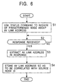
- step S1 the controller 36 queries a predetermined node (electronic apparatus) about an AV link address, using a status command in an AV/C command.
- the IEEE 1394 standard provides that the AV/C command and a response thereto must be transferred with the format shown in Fig. 7 in accordance with a function control protocol (FCP).
- FCP function control protocol
- destination_ID a node ID assigned to a receiver of the packet is described.
- source_ID a node ID assigned to a transmitter of the packet is described.
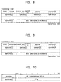
- an AV/C command frame having the format shown in Fig. 8 is set.
- an AV/C response frame having the format shown in Fig. 9 is set in the FCP frame.
- the television receiver 1 inquires about the AV link address of the video cassette recorder 2.
- the command shown in Fig. 10 is set.
- the status command defined in the IEEE 1394 standard is described.
- the value "XY” described in the opcode represents a command inquiring about the AV link address. Since the operand[0] is not particularly required in this case, the value "FF" is set there.
- the controller 36 controls the interface 31 to generate and output a command requesting the AV link address to the IEEE 1394 bus 21.
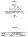
- Each electronic apparatus connected to the IEEE 1394 bus 21 performs the process shown in Fig. 11.
- the controller 46-1 in the video cassette recorder 2 is on standby until receiving, from the IEEE 1394 bus 21 via the interface 41-1, a command including a packet in which a node ID directed to the controller 46-1 is described as "destination ID".
- the controller 46-1 executes processing corresponding to the command in step S12.
- the controller 46-1 captures a packet in which "NID2" is described in the destination_ID shown in Fig. 7, by regarding this packet as directed to the controller 46-1.
- the command "XY” that requests the return of an AV link address (as shown in Fig. 10) is described in the opcode.
- the controller 46-1 describes its own address "1" (on the AV links 11) in an AV/C response frame having the format shown in Fig. 9, and outputs the packet to the IEEE 1394 bus 21.
- the controller 36 describes the same command "XY” as the command described in the opcode shown in Fig. 10, as shown in Fig. 12.
- the controller 36 describes, in the four LSB-side bits of the operand[0], the address "1" stored in its built-in memory as its own address on the AV links 11.
- the node ID "NID1" of the television receiver 1 is described in “destination_ID” (as shown in Fig. 7) of a packet output to the IEEE 1394 bus 21 by the video cassette recorder 2.
- the node ID "NID2" of the video cassette recorder 2 is described in "source_ID”.
- step S2 shown in Fig. 6 the controller 36 in the television receiver 1 is on standby until receiving a response packet directed to the controller 36.
- the controller 36 captures it.
- step S3 shown in Fig. 6 the controller 36 extracts the AV link address described in the lower four bits of the operand[0] in the FCP frame of the captured packet.
- step S4 the controller 36 reads the node ID "NID2" described in the source_ID of the captured packet, and stores it in a built-in memory so as to be correlated with the AV link address extracted in step S3.
- the controller 36 stores (AV link) address "1" (the address of "VCR-1") in its built-in memory so as to be correlated with node ID "NID2" of the video cassette recorder 2, as shown in Fig. 13.
- the television receiver 1 performs similar processing for the video cassette recorder 3, whereby (AV link) address 2 (the address of "VCR-2") is stored in a built-in table so as to correspond to the node ID "NID3" of the video cassette recorder 3, as shown in Fig. 13.
- each electronic apparatus connected to the IEEE 1394 bus 21 reads and correlates node unique IDs (on the IEEE 1394 bus 21) with node IDs is described below.
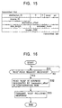
- the controller 36 in the television receiver 1 controls the interface 31, thereby requesting the video cassette recorder 2 in step S21 to read a node unique ID ("NUID") via the IEEE 1394 bus 21.
- the controller 36 outputs a read-request-for-data-block packet having the format shown in Fig. 15.
- the node ID "NID2" of the video cassette recorder 2 is described in the destination_ID
- the node ID "NID1" of the television receiver 1 is described in the source_ID.
- destination_offset a memory address at which the node unique ID of the video cassette recorder 2 is stored is described.
- the node unique ID is stored in a configuration ROM built into the controller 46-1. Accordingly, an address in the configuration ROM is described.
- the controller 46-1 in the video cassette recorder 2 executes a process shown as the flowchart in Fig. 16.
- step S31 the controller 46-1 is on standby until receiving a packet that requests the reading of a node unique ID.
- the controller 46-1 executes, in step S32, processing for reading, from the built-in configuration ROM, "NUID" stored in the address designated by the destination_offset in the packet.
- bus_info_block In the configuration ROM, data are stored based on the general ROM format shown in Fig. 17. Among the data, "bus_info_block” and “root_directory” are fixed in position. the bus_info_block has the format shown in Fig. 18. In this format, a 24-bit (3-byte) "node_vendor_id” and a 40-bit (5-byte) "chip_id” constitute a node unique ID.
- the chip_id consists of an 8-bit (1-byte) "chip_id_hi” and a 32-bit (4-byte) "chip_id_lo".
- step S33 the controller 46-1 describes the node unique ID read in step S32 in "data field" of the read-response-for-data block shown in Fig. 19, and outputs it to the IEEE 1394 bus 21.
- the node ID "NID1" of the television receiver 1 is described in the destination_ID
- the node ID "NID2" of the video cassette recorder 1 is described in the source_ID.
- step S22 the controller 36 in the television receiver 1 is on standby until receiving the response to the reading request from the video cassette recorder 2.
- step S24 the controller 36 extracts the packet source ID of a packet having the format shown in Fig. 19, and stores it in the table shown in Fig. 13 so as to be correlated with the node unique ID extracted in step S23.
- the television receiver 1 acquires a correspondence table (as shown in Fig. 13) in which the addresses (on buses) of the video cassette recorders 2 and 3 connected to both the AV links 11 and the IEEE 1394 bus 21 are described.
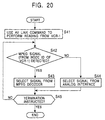
- the television receiver 1 executes the process shown in Fig. 20 when, for example, requesting the video cassette recorder 2 to read AV signals recorded in the videocassette 51-1.
- the controller 36 in the television receiver 1 controls the interface 35, thereby using an AV link command to instruct the video cassette recorder 2 to play the loaded videocassette 51-1.
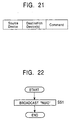
- a transmission format used on the AV links 11 is described as shown in Fig. 21.
- the AV link address of a source device, from which the packet is output, is described.
- the AV link address of a destination device to which the packet is transmitted is described.
- the AV link address "0" of the television receiver 1 is described as the source device
- the AV link address "1" of the video cassette recorder 2 is described as the destination device.
- a command follows the destination device.
- a command representing the start of the reading of a record is described.
- the controller 46-1 in the video cassette recorder 2 controls the RF amplifier 43-1 to read the AV signals recorded in the videocassette 51-1.
- the controller 46-1 monitors the output (or input) of the RF amplifier 43-1. When detecting digital AV signals as the AV signals being read, the controller 46-1 controls the RF amplifier 43-1 to output the digital AV signals to the D-VHS processor 42-1. When detecting analog signals as the AV signals being read, the controller 46-1 controls the RF amplifier 43-1 to output the analog signals to the VHS processor 45-1.
- the D-VHS processor 42-1 transforms the input digital AV signals, which has a D-VHS format, into digital AV signals having an MPEG format, and outputs the signals to the IEEE 1394 bus 21 via the interface 41-1.
- the node ID "NID1" of the television receiver 1 is described in the destination_ID of the output packet
- the node ID "NID2" of the video cassette recorder 2 is described in the source_ID of the output packet.
- the VHS processor 45-1 processes the input analog video signals and outputs the processed signals to the AV links 11 via the interface 44-1.
- step S42 the controller 36 in the television receiver 1 monitors an output from the interface 31, and determines whether a packet in which its own node ID "NID1" is described as the destination_ID is output. If the packet is detected, the controller 36 determines whether MPEG signals are detected in which the source_ID is the node ID "NID2" of the video cassette recorder 2. If a packet satisfying the above-described conditions exists, the controller 36 controls the switch circuit 33 in step S43 to select the output of the MPEG decoder 32. As a result, the digital AV data, captured via the interface 32, are decoded by the MPEG decoder 32, and the decoded data are output and displayed on the display 34.
- step S45 The controller 36 determines whether termination of the process has been instructed. If it has not been instructed, the process returns to step S42 and the subsequent steps are repeatedly executed.
- step S42 If the process has determined in step S42 that no digital AV signals have been transferred from the video cassette recorder 2 via the IEEE 1394 bus 21, the process proceeds to step S44, and the controller 36 controls the switch circuit 33 to select the output of the interface 35.
- the controller 36 controls the switch circuit 33 to select the output of the interface 35.
- the television receiver 1 can output and display the read signals on the display 34.
- the IEEE 1394 bus 21 is used to recognize each AV link address in the above-described embodiment, the AV links 11 may conversely be used to recognize the node ID of each electronic apparatus.
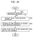
- each electronic apparatus connected to the AV links 11, simultaneously broadcasts (or multicasts) its own node ID to the other electronic apparatuses via the AV links 11.
- Fig. 23 shows the structure of a packet used in the broadcasting or multicasting. From the head of the packet, "Start Sequence”, “Header Block”, “Command Block” including “opcode”, and “Command Block 1" to “Command Block 8" are arranged in this order.
- the AV link address (e.g., the AV link address "1" of the video cassette recorder 2) of an electronic apparatus having transmitted this packet is described.
- the value "15” that represents broadcast (general call) is described (See Fig. 2).
- an electronic apparatus regards a packet having the value as being directed to the electronic apparatus, and captures the packet.
- the value "15” represents general call.
- a command that represents a declaration of a node unique ID is described.
- an 8-byte part, separated from a 64-byte node unique ID is set.
- EOM End of Message
- ACK Acknowledge
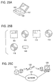
- step S61 the controller 36 in the television receiver 1 is on standby until receiving a broadcast (general call).
- step S62 the controller 36 extracts, from the broadcast packet, eight 8-byte separated parts (constituting the 64-byte node unique ID) in the eight "Operand" parts of the eight command blocks.
- step S63 the controller 36 further extracts the AV link address of a source device from the received packet.
- the controller 36 further extracts the AV link address of the source device from the received packet.
- the AV link address e.g., the AV link address "1" of the video cassette recorder 2 of an electronic apparatus that transmitted the packet as a broadcast is extracted.
- step S64 the controller 36 stores the node unique ID extracted in step S62 and the AV link address extracted in step S63 so that they are correlated to each other in a table, as shown in Fig. 13.
- each node ID and each node unique ID can be established similarly to the above-described process.
- the program can be provided to the user with a hard disk 102 or a semiconductor memory 103 as a recording medium built into a personal computer 101, on which the program is preinstalled.
- the program can also be provided as package software obtained by temporarily or permanently storing the program on a recording medium such as a floppy disk 111, a CD-ROM 112, a magneto-optical disk 113, a digital versatile disk 114, a magnetic disk 115, or a semiconductor memory 116.
- a recording medium such as a floppy disk 111, a CD-ROM 112, a magneto-optical disk 113, a digital versatile disk 114, a magnetic disk 115, or a semiconductor memory 116.
- the transferred program can be stored in a built-in hard disk drive in the personal computer 123.
- medium in this specification means a broad concept including all the above-described types of medium.
- a step that describes the program provided from the medium includes not only processes which are time-sequentially executed along a predetermined order, but also processes which are not always time-sequentially executed and which are executed in parallel or separately.
- system means the entirety of a plurality of electronic apparatuses.
Landscapes
- Engineering & Computer Science (AREA)
- Multimedia (AREA)
- Signal Processing (AREA)
- Two-Way Televisions, Distribution Of Moving Picture Or The Like (AREA)
- Information Transfer Systems (AREA)
- Television Signal Processing For Recording (AREA)
- Small-Scale Networks (AREA)
Applications Claiming Priority (2)
| Application Number | Priority Date | Filing Date | Title |
|---|---|---|---|
| JP11108821A JP2000307613A (ja) | 1999-04-16 | 1999-04-16 | 情報処理装置および方法、並びに媒体 |
| JP10882199 | 1999-04-16 |
Publications (2)
| Publication Number | Publication Date |
|---|---|
| EP1045583A2 true EP1045583A2 (de) | 2000-10-18 |
| EP1045583A3 EP1045583A3 (de) | 2003-03-12 |
Family
ID=14494390
Family Applications (1)
| Application Number | Title | Priority Date | Filing Date |
|---|---|---|---|
| EP00303132A Withdrawn EP1045583A3 (de) | 1999-04-16 | 2000-04-13 | Anlage und Verfahren zur Bearbeitung von Informationen, und damit ausgestattetes Medium |
Country Status (2)
| Country | Link |
|---|---|
| EP (1) | EP1045583A3 (de) |
| JP (1) | JP2000307613A (de) |
Cited By (1)
| Publication number | Priority date | Publication date | Assignee | Title |
|---|---|---|---|---|
| WO2003092279A1 (en) * | 2002-04-24 | 2003-11-06 | Thomson Licensing S.A. | Method and apparatus for specifying connections for devices on a data bus network |
Families Citing this family (2)
| Publication number | Priority date | Publication date | Assignee | Title |
|---|---|---|---|---|
| TWI330763B (en) * | 2006-05-26 | 2010-09-21 | Au Optronics Corp | Exposing apparatus and exposing system |
| CN106128488A (zh) * | 2015-05-08 | 2016-11-16 | 王旭 | 数字录放机应用系统 |
Family Cites Families (3)
| Publication number | Priority date | Publication date | Assignee | Title |
|---|---|---|---|---|
| US5625350A (en) * | 1993-12-27 | 1997-04-29 | Alpine Electronics, Inc. | Audio/video communication system and method |
| US5841987A (en) * | 1994-08-19 | 1998-11-24 | Thomson Consumer Electronics, Inc. | Simple bus and interface system for consumer digital equipment |
| JP3528480B2 (ja) * | 1996-11-19 | 2004-05-17 | ソニー株式会社 | Epg機器及びその制御方法 |
-
1999
- 1999-04-16 JP JP11108821A patent/JP2000307613A/ja not_active Withdrawn
-
2000
- 2000-04-13 EP EP00303132A patent/EP1045583A3/de not_active Withdrawn
Cited By (2)
| Publication number | Priority date | Publication date | Assignee | Title |
|---|---|---|---|---|
| WO2003092279A1 (en) * | 2002-04-24 | 2003-11-06 | Thomson Licensing S.A. | Method and apparatus for specifying connections for devices on a data bus network |
| US8001300B2 (en) | 2002-04-24 | 2011-08-16 | Thomson Licensing | Method and apparatus for specifying analog connections for data bus network devices having both digital and analog outputs |
Also Published As
| Publication number | Publication date |
|---|---|
| EP1045583A3 (de) | 2003-03-12 |
| JP2000307613A (ja) | 2000-11-02 |
Similar Documents
| Publication | Publication Date | Title |
|---|---|---|
| US7675541B2 (en) | Display apparatus and control method | |
| US7372508B2 (en) | Information outputting apparatus, information reporting method and information signal supply route selecting method | |
| US6191822B1 (en) | Method of and apparatus for separating audio and video data from a combined audio/video stream of data | |
| JP2001249802A (ja) | 伝送方法、伝送システム、伝送制御装置及び入力装置 | |
| US6144411A (en) | Image processing apparatus with format conversion capabilities | |
| US7150032B1 (en) | Electronic apparatus and connection mode setting method | |
| JPH11177957A (ja) | 入出力装置および入出力方法、並びに受信装置 | |
| US7386742B2 (en) | Method and apparatus for controlling power to a first and second circuit based on an operational mode and connecting state of an information processing apparatus | |
| US6307842B1 (en) | Information signal transmitting apparatus | |
| US6976267B1 (en) | Method and apparatus for controlling connections between devices | |
| US7448060B2 (en) | Method for determining signal path | |
| KR100697962B1 (ko) | 디지털 방송의 수신 시스템, 디지털 방송 수신 시스템에 있어서의 데이터 송신 방법 및 디지털 방송의 수신 장치 | |
| JP2000184303A5 (ja) | ディジタル放送受信システム、ディジタル放送受信システムにおけるデータ送信方法、及びディジタル放送の受信装置 | |
| JP2000188725A (ja) | ディジタル放送の受信システム及びディジタル放送の受信装置 | |
| US6993606B1 (en) | Communication method and communication apparatus for data communication between devices connected by a network | |
| EP1045583A2 (de) | Anlage und Verfahren zur Bearbeitung von Informationen, und damit ausgestattetes Medium | |
| KR20010076337A (ko) | 통신 방법 및 통신 장치 | |
| MXPA01001975A (es) | Metodo para determinar automaticamente la configuracion de un aparato de procesamiento de video de entradas multiples. | |
| JP2000115676A (ja) | 情報再生装置、情報記録再生装置、情報選択出力装置及び電子機器システム | |
| US20030058369A1 (en) | Control device, controlled device with passing-through function, controlled device, controlled method, medium and program | |
| JP4491956B2 (ja) | 通信方法、通信システム及び通信装置 | |
| JP2001245225A (ja) | 双方向通信回線を利用した機器間接続システム | |
| JP2001285828A (ja) | 双方向通信回線を利用した機器間接続システム | |
| JP2004289866A (ja) | 表示装置および方法、プログラム、並びに表示システム | |
| JP4193043B2 (ja) | データ通信装置およびデータ通信方法 |
Legal Events
| Date | Code | Title | Description |
|---|---|---|---|
| PUAI | Public reference made under article 153(3) epc to a published international application that has entered the european phase |
Free format text: ORIGINAL CODE: 0009012 |
|
| AK | Designated contracting states |
Kind code of ref document: A2 Designated state(s): AT BE CH CY DE DK ES FI FR GB GR IE IT LI LU MC NL PT SE |
|
| AX | Request for extension of the european patent |
Free format text: AL;LT;LV;MK;RO;SI |
|
| PUAL | Search report despatched |
Free format text: ORIGINAL CODE: 0009013 |
|
| AK | Designated contracting states |
Kind code of ref document: A3 Designated state(s): AT BE CH CY DE DK ES FI FR GB GR IE IT LI LU MC NL PT SE Designated state(s): AT BE CH CY DE DK ES FI FR GB GR IE IT LI LU MC NL PT SE |
|
| AX | Request for extension of the european patent |
Extension state: AL LT LV MK RO SI |
|
| 17P | Request for examination filed |
Effective date: 20030829 |
|
| AKX | Designation fees paid |
Designated state(s): DE FR GB IT NL |
|
| STAA | Information on the status of an ep patent application or granted ep patent |
Free format text: STATUS: THE APPLICATION HAS BEEN WITHDRAWN |
|
| 18W | Application withdrawn |
Effective date: 20040107 |