EP1045475B1 - Schraubenlose Anschluss- oder Verbindungsklemme für elektrische Leiter - Google Patents
Schraubenlose Anschluss- oder Verbindungsklemme für elektrische Leiter Download PDFInfo
- Publication number
- EP1045475B1 EP1045475B1 EP00106904A EP00106904A EP1045475B1 EP 1045475 B1 EP1045475 B1 EP 1045475B1 EP 00106904 A EP00106904 A EP 00106904A EP 00106904 A EP00106904 A EP 00106904A EP 1045475 B1 EP1045475 B1 EP 1045475B1
- Authority
- EP
- European Patent Office
- Prior art keywords
- legs
- contact frame
- web
- spring
- clamping
- Prior art date
- Legal status (The legal status is an assumption and is not a legal conclusion. Google has not performed a legal analysis and makes no representation as to the accuracy of the status listed.)
- Expired - Lifetime
Links
- 239000004020 conductor Substances 0.000 title claims description 20
- 238000005452 bending Methods 0.000 claims description 7
- 238000004873 anchoring Methods 0.000 claims description 4
- 230000037431 insertion Effects 0.000 claims description 4
- 238000003780 insertion Methods 0.000 claims description 4
- 210000001331 nose Anatomy 0.000 claims 3
- 239000000463 material Substances 0.000 description 7
- RYGMFSIKBFXOCR-UHFFFAOYSA-N Copper Chemical compound [Cu] RYGMFSIKBFXOCR-UHFFFAOYSA-N 0.000 description 2
- 208000000260 Warts Diseases 0.000 description 2
- 229910052802 copper Inorganic materials 0.000 description 2
- 239000010949 copper Substances 0.000 description 2
- 201000010153 skin papilloma Diseases 0.000 description 2
- 239000002699 waste material Substances 0.000 description 2
- 230000001154 acute effect Effects 0.000 description 1
- 229910045601 alloy Inorganic materials 0.000 description 1
- 239000000956 alloy Substances 0.000 description 1
- 238000010276 construction Methods 0.000 description 1
- 230000000694 effects Effects 0.000 description 1
- 210000003746 feather Anatomy 0.000 description 1
- 230000014509 gene expression Effects 0.000 description 1
- 239000010935 stainless steel Substances 0.000 description 1
- 229910001220 stainless steel Inorganic materials 0.000 description 1
- 230000007704 transition Effects 0.000 description 1
- 238000005406 washing Methods 0.000 description 1
Images


Classifications
-
- H—ELECTRICITY
- H01—ELECTRIC ELEMENTS
- H01R—ELECTRICALLY-CONDUCTIVE CONNECTIONS; STRUCTURAL ASSOCIATIONS OF A PLURALITY OF MUTUALLY-INSULATED ELECTRICAL CONNECTING ELEMENTS; COUPLING DEVICES; CURRENT COLLECTORS
- H01R9/00—Structural associations of a plurality of mutually-insulated electrical connecting elements, e.g. terminal strips or terminal blocks; Terminals or binding posts mounted upon a base or in a case; Bases therefor
- H01R9/22—Bases, e.g. strip, block, panel
- H01R9/24—Terminal blocks
-
- H—ELECTRICITY
- H01—ELECTRIC ELEMENTS
- H01R—ELECTRICALLY-CONDUCTIVE CONNECTIONS; STRUCTURAL ASSOCIATIONS OF A PLURALITY OF MUTUALLY-INSULATED ELECTRICAL CONNECTING ELEMENTS; COUPLING DEVICES; CURRENT COLLECTORS
- H01R4/00—Electrically-conductive connections between two or more conductive members in direct contact, i.e. touching one another; Means for effecting or maintaining such contact; Electrically-conductive connections having two or more spaced connecting locations for conductors and using contact members penetrating insulation
- H01R4/28—Clamped connections, spring connections
- H01R4/48—Clamped connections, spring connections utilising a spring, clip, or other resilient member
- H01R4/4809—Clamped connections, spring connections utilising a spring, clip, or other resilient member using a leaf spring to bias the conductor toward the busbar
- H01R4/48185—Clamped connections, spring connections utilising a spring, clip, or other resilient member using a leaf spring to bias the conductor toward the busbar adapted for axial insertion of a wire end
- H01R4/48275—Clamped connections, spring connections utilising a spring, clip, or other resilient member using a leaf spring to bias the conductor toward the busbar adapted for axial insertion of a wire end with an opening in the housing for insertion of a release tool
-
- H—ELECTRICITY
- H01—ELECTRIC ELEMENTS
- H01R—ELECTRICALLY-CONDUCTIVE CONNECTIONS; STRUCTURAL ASSOCIATIONS OF A PLURALITY OF MUTUALLY-INSULATED ELECTRICAL CONNECTING ELEMENTS; COUPLING DEVICES; CURRENT COLLECTORS
- H01R4/00—Electrically-conductive connections between two or more conductive members in direct contact, i.e. touching one another; Means for effecting or maintaining such contact; Electrically-conductive connections having two or more spaced connecting locations for conductors and using contact members penetrating insulation
- H01R4/28—Clamped connections, spring connections
- H01R4/48—Clamped connections, spring connections utilising a spring, clip, or other resilient member
- H01R4/4809—Clamped connections, spring connections utilising a spring, clip, or other resilient member using a leaf spring to bias the conductor toward the busbar
- H01R4/4828—Spring-activating arrangements mounted on or integrally formed with the spring housing
- H01R4/48365—Spring-activating arrangements mounted on or integrally formed with the spring housing with integral release means
Definitions
- Clamps of this type are primarily constructed in two parts because on the one hand requires high stability and good electrical conductivity what is indicated by e.g. contact frame made of copper fulfilled and, on the other hand, reliable clamping forces provided by a clamping spring which exerts optimal spring forces even under the influence of temperature. Therefore, such a clamping spring is made of a suitable material, e.g. out a CrNi alloy.
- the screwless clamp described in DE 23 49 614 C2 from The present invention is based on two parts.
- Your contact frame consists of a U-profile, and the clamping spring is such clamped between the two U-legs that their spring clip with one of the two U-legs is firmly connected while its at an acute angle bent and facing clamp legs the opposite Apply U-leg of the contact frame to form clamping points.
- screwless connection or Connection terminals corresponding to those submitted in 1973 Patent registration proven to this day.
- CH 426 974 is a generic, screwless connection or Connection clamp for electrical conductors known, in which both U-legs of the contact frame one abutment for the clamping edge one each Form spring legs.
- the present invention has for its object the clamp train that their terminal points cannot influence each other and that dealt with the material of the contact frame in a material-saving manner becomes.
- the invention is further characterized in that according to it Designed terminal block allows connection in which the conductor can be fed from several different directions. In which in terms of related art, this is just two defined each other opposite directions possible.
- a screwless connection or designated in its entirety with 10 Connecting terminal for electrical conductors, not shown, includes one Contact frame 11 and a clamping spring 12th
- the contact frame 11 consists of a material of high electrical Conductivity and high inherent rigidity, preferably made of copper.
- the clamping spring 12 consists of excellent spring properties and temperature-resistant material, preferably made of stainless steel.
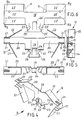
- FIGS. 1 to 3 The structure of a contact frame 11 will be explained with reference to FIGS. 1 to 3.
- Fig. 3 which shows the strip-shaped material blank, corresponding parts of the contact frame are designated with the same reference numerals, but with an apostrophe added.
- a contact frame 11 initially includes a central U-profile 13 with a U-web 14 and aligned parallel to each other U-legs 15.
- the contact frame 11 shown as an example in the drawings is set up for four main terminal points and accordingly has four Extensions 16, which are connected to the four ends of the U-legs and are bent outwards, as very clearly shown in FIGS. 1 and 2.
- the U-web 14 forms the U-profile 13 together with the extensions 16 about an H or I or Double T shape. While the two lower extensions 16 with respect to FIG. 2 form a right angle with the U-profile 13 or the longitudinal central axis L, is the angle w which the upper extensions 16 form to the longitudinal central axis L, less and is about 60 ° in the embodiment. At this It should be noted that the angular positions correspond to the requirements will be set and that asymmetrical arrangements of course are possible if this is desired or required on a case-by-case basis should.
- FIG. 1 A comparison of FIG. 1 or the main view in FIG. 2 with the representation of the blank according to FIG. 3 shows that the U-legs 15 are produced by a 90 ° bend around the bending lines B 1 and the protruding extensions 16 by additional bending around the bending lines, which are labeled B 2 in FIG. 3.
- FIG. 6 which shows its strip-shaped material cut
- corresponding parts of the clamping spring are identified with the same reference numbers , but with an apostrophe.
- the clamping spring 12 has a central clamping spring web 19 on. It is followed by a striving arrangement and lying in the same plane, two arms 20 on.
- the central spring clip 19 and the arms 20 are, as is particularly the case in FIG. 4 and directly 5 above, show about twice the wall thickness embossed against each other.
- spring legs 22 which are released by bends 21.
- the bending lines associated with the bends 21 are designated by B 3 in FIG. 6.
- the spring legs 22 are bent obliquely or inclined away from one another and bent outward into the configuration shown in FIG. 4 and the front view of FIG. 5 in the direction of the arrow V of FIG. 4.
- Fig. 7 illustrates the structural assignment of the clamping spring 12 to Contact frame 11. Further understanding can be seen from the view in FIG. 8 win. First, it shows the overall skeletal structure very nicely the entire connection terminal, since both with regard to the contact frame 11 as well as with respect to the clamping spring 12, each of a skeletal configuration can be spoken. Furthermore, Fig. 8 shows a certain frame construction of the contact frame insofar as all elements, in particular the clamping spring with its spring legs 22 between the extensions 16 are included.
- FIG. 8 shows the function of the extensions 16 as a clamping abutment for the spring legs 22, which bear against the inner sides of the extensions 16 under spring pressure. Since no conductors are shown in the figures, arrows in FIG. 8 illustrate conductor insertion directions R 1 to R 4 . At the same time it is clear that the tabs 17 catch the front stripped conductor end and can steer against the respective extension 16.
- the inclined tongue 24 in the central region of the clamping spring web 19 forms, together with the inner surface of the central U-web 14 of the contact frame 11, a secondary clamping point.
- the valley forms a guide between the wart-like embossments 18.
- a terminal block 27 with a bell-type is shown Housing body 28 and a bottom closing this Floor 29.
- the terminal block 27 includes a series of parallel or parallel. Terminals of the type according to the invention arranged one behind the other. Since each terminal has four main terminal points, there are accordingly rows of conductor insertion openings 30 accessible from four directions.
- the auxiliary terminal point to be fitted from the bottom 29 with a conductor in the insertion direction R 5 can be used, for example, to connect an earth conductor.
- edge notches 31 on the two upper extensions 16 of the contact frame 11. These narrow the extension 16 in question and form a type of window through which a tool such as a screwdriver or the like can be inserted in order to move in the direction R 6 (FIG. 10) by pressing down the spring leg 22 located below when the conductor is inserted, to open the relevant clamping point and to be able to remove the conductor.
Landscapes
- Clamps And Clips (AREA)
- Connections Arranged To Contact A Plurality Of Conductors (AREA)
- Connections By Means Of Piercing Elements, Nuts, Or Screws (AREA)
- Multi-Conductor Connections (AREA)
Description
- mit einem Kontaktrahmen, der ein U-Profil mit einem U-Steg und parallel zueinander ausgerichteten U-Schenkeln beinhaltet,
- und einer mit dem Kontaktrahmen zusammenwirkenden Klemmfeder,
- die einen Klemmfedersteg und Federschenkel aufweist,
- deren Klemmfedersteg mit dem U-Profil des Kontaktrahmens verbunden ist und deren Federschenkel mit ihren Klemmkanten an Widerlagern des Kontaktrahmens anliegen.
- dass ein oder beide U-Schenkel des U-Profils des Kontaktrahmens in deren Längsrichtung gesehen jeweils an einer oder beiden Stirnseite(n) über den U-Steg des U-Profils hervorragende Fortsätze aufweisen, die vom U-Steg und den U-Schenkeln des U-Profils weg gebogen sind, wobei die Fortsätze in einer parallel zum U-Steg liegenden Ebene angeordnet sind,
- dass an den Längsseiten des Klemmfedersteges der Klemmfeder jeweils ein vom Klemmfedersteg wegweisender Arm vorhanden ist und an den freien Enden der beiden Arme jeweils ein oder zwei Federschenkel freigeschnitten sind, die jeweils über eine Biegekante mit dem Arm verbunden und von diesem in eine Richtung rechtwinklig abgebogen sind, wobei die freien Enden der Federschenkel zum Klemmfedersteg hin gerichtet sind, und
- dass die Klemmfeder derart am Kontaktrahmen angeordnet ist, dass sich die Längskanten des Klemmfedersteges parallel zur Längsrichtung des Kontaktrahmens erstrecken und dass der Klemmfedersteg der Klemmfeder über die beiden U-Schenkel des U-Profils des Kontaktrahmens an diesem angreift, wodurch sich ein geschlossener, stabiler Kontaktrahmen ergibt,
- Fig. 1
- eine perspektivische Ansicht des Kontaktrahmens der schraubenlosen Anschluss- oder Verbindungsklemme entsprechend der Erfindung,
- Fig. 2
- eine Stirnansicht mit Seitenansicht und Aufsicht des Kontaktrahmens der Fig. 1,
- Fig. 3
- eine Aufsicht auf den noch flachen Materialzuschnitt, aus dem der Kontaktrahmen nach Fig. 1 erzeugt wird,
- Fig. 4
- eine perspektivische Ansicht der zugehörigen Klemmfeder in lagegerechter Zuordnung zu dem in Fig. 1 gezeigten Kontaktrahmen,
- Fig. 5
- eine Frontalansicht der in Fig. 4 gezeigten Klemmfeder mit Seitenansicht und Aufsicht,
- Fig. 6
- eine Aufsicht auf den noch ebenen Zuschnitt, aus dem die Klemmfeder nach Fig. 4 erzeugt wird,
- Fig. 7
- eine perspektivische Darstellung von Kontaktrahmen und Klemmfeder in lagegerechter Zuordnung vor ihrem Zusammenfügen,
- Fig. 8
- eine Ansicht auf die Verbindungsklemme in Richtung des Pfeiles VIII in Fig. 7,
- Fig. 9
- eine schaubildliche Darstellung einer in einem Isolier-Klemmengehäuse befindlichen Klemme entsprechend der Erfindung und
- Fig. 10
- eine Ansicht dazu in Richtung des Ansichtspfeiles X in Fig. 9.
Claims (14)
- Schraubenlose Anschluss- oder Verbindungsklemme (10) für elektrische Leiterdadurch gekennzeichnet,mit einem Kontaktrahmen (11), der ein U-Profil (13) mit einem U-Steg (14) und parallel zueinander ausgerichteten U-Schenkeln (15) beinhaltet,und einer mit dem Kontaktrahmen (11) zusammenwirkenden Klemmfeder (12),die einen Klemmfedersteg (19) und Federschenkel (22) aufweist,deren Klemmfedersteg (19) mit dem U-Profil (13) des Kontaktrahmens (11) verbunden ist und deren Federschenkel (22) mit ihren Klemmkanten an Widerlagem des Kontaktrahmens (11) anliegen,dass ein oder beide U-Schenkel (15) des U-Profils (13) des Kontaktrahmens (11) in deren Längsrichtung gesehen jeweils an'einer oder beiden Stirnseite(n) über den U-Steg (14) des U-Profils (13) hervorragende Fortsätze (16) aufweisen, die vom U-Steg (14) und den U-Schenkeln (15) des U-Profils (13) weg gebogen sind, wobei die Fortsätze (16) in einer parallel zum U-Steg (14) liegenden Ebene angeordnet sind,dass an den Längsseiten des Klemmfedersteges (19) der Klemmfeder (12) jeweils ein vom Klemmfedersteg (19) wegweisender Arm (20) vorhanden ist und an den freien Enden der beiden Arme (20) jeweils ein oder zwei Federschenkel (22) freigeschnitten sind, die jeweils über eine Biegekante (21) mit dem Arm (20) verbunden und von diesem in eine Richtung rechtwinklig abgebogen sind, wobei die freien Enden der Federschenkel (22) zum Klemmfedersteg (19) hin gerichtet sind, unddass die Klemmfeder (12) derart am Kontaktrahmen (11) angeordnet ist, dass sich die Längskanten des Klemmfedersteges (19) parallel zur Längsrichtung des Kontaktrahmens (11) erstrecken und dass der Klemmfedersteg (19) der Klemmfeder (12) über die beiden U-Schenkel des U-Profils (13) des Kontaktrahmens (11) an diesem angreift, wodurch sich ein geschlossener; stabiler Kontaktrahmen ergibt, wobei die Fortsätze jeweils eine zum jeweiligen an der anderen Stirnseite des entsprechenden U-Schenkels (15) angeordneten Fortsatz (16) weisende Innenfläche aufweisen und die Federschenkel (22) der Klemmfeder (12) jeweils an der Innenseite des jeweiligen Fortsatzes (16) des Kontaktrahmens (11) angeordnet sind, wobei die Fortsätze (16) die Widerlager für die Klemmkanten der Federschenkel (22) bilden.
- Klemme nach Anspruch 1, dadurch gekennzeichnet, dass sie vier Haupt-Kontaktstellen und mit Blick auf eine der flachen Seiten des U-Steges (14) des U-Profils (13) des Kontaktrahmens (11) im wesentlichen eine H- oder I- bzw. Doppel-T-Form aufweist.
- Klemme nach Anspruch 1, dadurch gekennzeichnet, dass sie zwei Haupt-Kontaktstellen und mit Blick auf eine der flachen Seiten des U-Steges (14) des U-Profils (13) des Kontaktrahmens (11) im wesentlichen die Form eines S, Z oder T aufweist.
- Klemme nach Anspruch 1, dadurch gekennzeichnet, dass sie drei Haupt-Kontaktstellen und mit Blick auf eine der flachen Seiten des U-Steges (14) des U-Profils (13) des Kontaktrahmens (11) im wesentlichen eine um einen Schenkel reduzierte H- oder I- bzw. Doppel-T-Form aufweist.
- Klemme nach einem der Ansprüche 2 bis 4, dadurch gekennzeichnet, dass die Biegewinkel (W) zwischen den von den U-Schenkeln (15) des U-Profils (13) abgebogenen Fortsätzen (16) und einer Langsmittelachse (L) des U-Stegs (14 zwischen 60° und 90° liegen.
- Klemme nach einem der vorherigen Ansprüche, dadurch gekennzeichnet, dass benachbart den Fortsätzen (16) aus den U-Schenkeln (15) des U-Profils (13) des Kontaktrahmens (11) Lappen (17) ausgeprägt sind, die mit den Fortsätzen (16) eine trichterförmige Führung für ein in die Klemmstelle einzusteckendes Leiterende dienen.
- Klemme nach einem der vorherigen Ansprüche, dadurch gekennzeichnet, dass am Klemmfedersteg (19) Verankerungsnasen (23) zum verriegelnden Angriff am U-Profil (13) des Kontaktrahmens (11) ausgeformt sind.
- Klemme nach Anspruch 7, dadurch gekennzeichnet, dass die Verankerungsnasen (23) die U-Schenkel (15) des U-Profils (13) des Kontaktrahmens (11) teilumgreifen und dass in den U-Schenkeln (15) Aussparungen vorhanden sind, in die die Verankerungsnasen (23) eingreifen.
- Klemme nach Anspruch 8. dadurch gekennzeichnet, dass die Aussparungen von Freischnitten (26) gebildet sind, die durch das Ausprägen der Lappen (17) in den U-Schenkeln verbleiben.
- Klemme nach Anspruch 1 oder einem der vorhergehenden, dadurch gekennzeichnet, dass der Klemmfedersteg (19) die U-Schenkel (15) des U-Profils (13) des Kontaktrahmens (11) überbrückt und zwischen sich und der Innenseite des U-Steges (14) einen Freiraum für eine Nebenklemmstelle belässt.
- Klemme nach Anspruch 10, dadurch gekennzeichnet, dass aus dem Klemmfedersteg (19) eine Nebenklemmstellen-Federzunge (24) ausgeschnitten ist.
- Klemme nach einem der vorhergehenden Ansprüche, dadurch gekennzeichnet, dass der U-Steg (14) des U-Profils (13) des Kontaktrahmens (11) mit nach innen weisenden Ausdrückungen (18) versehen ist, die zwischen sich eine Leiterführung für die Nebenklemmstelle bereitstellen.
- Klemme nach einem der vorhergehenden Ansprüche, dadurch gekennzeichnet, dass die Fortsätze (16) des Kontaktrahmens (11) mit Randausklinkungen (31) zur Betätigung der Federschenkel (22) mit einem Klemmstellenöffnungswerkzeug wie Schraubendreher o.ä. versehen sind.
- Klemme nach einem der vorhergehenden Ansprüche, dadurch gekennzeichnet, dass die U-Schenkel (15) des U-Profils (13) des Kontaktrahmens (11) im Bereich zwischen den Lappen (17) und den Fortsätzen (16) mit ihren Außenseiten Leitereinschubanschläge bilden.
Applications Claiming Priority (2)
| Application Number | Priority Date | Filing Date | Title |
|---|---|---|---|
| DE19917142A DE19917142C1 (de) | 1999-04-16 | 1999-04-16 | Schraubenlose Anschluß- oder Verbindungsklemme für elektrische Leiter |
| DE19917142 | 1999-04-16 |
Publications (3)
| Publication Number | Publication Date |
|---|---|
| EP1045475A2 EP1045475A2 (de) | 2000-10-18 |
| EP1045475A3 EP1045475A3 (de) | 2001-04-04 |
| EP1045475B1 true EP1045475B1 (de) | 2002-06-19 |
Family
ID=7904736
Family Applications (1)
| Application Number | Title | Priority Date | Filing Date |
|---|---|---|---|
| EP00106904A Expired - Lifetime EP1045475B1 (de) | 1999-04-16 | 2000-03-31 | Schraubenlose Anschluss- oder Verbindungsklemme für elektrische Leiter |
Country Status (4)
| Country | Link |
|---|---|
| EP (1) | EP1045475B1 (de) |
| AT (1) | ATE219606T1 (de) |
| DE (1) | DE19917142C1 (de) |
| ES (1) | ES2177490T3 (de) |
Cited By (2)
| Publication number | Priority date | Publication date | Assignee | Title |
|---|---|---|---|---|
| WO2012083320A1 (de) | 2010-12-21 | 2012-06-28 | Tridonic Connection Technology Gmbh & Co Kg | Anschluss- oder verbindungsklemme für elektrische leiter |
| DE102014205299A1 (de) | 2013-03-21 | 2014-09-25 | Tridonic Connection Technology Gmbh & Co Kg | Anschluss- oder Verbindungsklemme für elektrische Leiter, sowie Leuchte |
Families Citing this family (7)
| Publication number | Priority date | Publication date | Assignee | Title |
|---|---|---|---|---|
| DE10163056B4 (de) * | 2001-12-21 | 2004-07-08 | Bjb Gmbh & Co.Kg | Lampenfassung |
| DE10163055B4 (de) * | 2001-12-21 | 2004-07-08 | Bjb Gmbh & Co.Kg | Lampenfassung, insbesondere Fassung für Halogen-Hochvoltlampen |
| DE10163057B4 (de) * | 2001-12-21 | 2004-07-08 | Bjb Gmbh & Co.Kg | Fassung für Hochvoltlampen |
| DE102005042660B4 (de) * | 2005-09-08 | 2007-12-13 | Conrad Stanztechnik Gmbh | Anschlußklemme mit einem Isoliergehäuse |
| US8262405B1 (en) * | 2011-03-15 | 2012-09-11 | Avx Corporation | Wire-to-wire connector |
| FR3005213B1 (fr) * | 2013-04-30 | 2016-09-23 | Fabrication D'applications Et De Realisations Electroniques | Connecteur electrique a lamelle de contact |
| DE102015000331A1 (de) * | 2015-01-09 | 2016-07-14 | DEHN + SÖHNE GmbH + Co. KG. | Kontaktanordnung für steckbare Überspannungsableiter |
Citations (4)
| Publication number | Priority date | Publication date | Assignee | Title |
|---|---|---|---|---|
| DE1898970U (de) * | 1964-06-08 | 1964-08-20 | Wago Klemmenwerk G M B H | Federdruck-klemme. |
| DE2258156A1 (de) * | 1972-11-28 | 1974-05-30 | Wago Kontakttechnik Gmbh | Elektrische kupplung zum schraubenlosen verbinden elektrischer leitungen |
| DE7902093U1 (de) * | 1979-01-26 | 1979-07-05 | Tony Adels, Elektro- U. Waermetechnik Gmbh & Co Kg, 5060 Bergisch Gladbach | Kontakteinsatz, bestehend aus einer Klemmfeder und einem Kontaktrahmen, insbesondere für Lichtbänder |
| AT378628B (de) * | 1983-03-21 | 1985-09-10 | Electro Terminal Gmbh | Schraubenlose verbindungsklemme |
Family Cites Families (7)
| Publication number | Priority date | Publication date | Assignee | Title |
|---|---|---|---|---|
| CH426974A (de) * | 1965-08-17 | 1966-12-31 | Vossloh Werke Gmbh | Schraubenlose Lüsterklemme |
| DE2349614C2 (de) * | 1973-10-03 | 1983-01-13 | Wago-Kontakttechnik Gmbh, 4950 Minden | Schraubenlose Anschluß- oder Verbindungsklemme für elektrische Leiter |
| FR2249422A2 (en) * | 1973-10-29 | 1975-05-23 | Gmt Sa | Keyboard type tumbler electric switch - has folded spring strip connectors with curved contact ends |
| CA1109132A (en) * | 1978-10-31 | 1981-09-15 | Keith R. Cribb | Terminals for receiving both quick connect terminals and stripped wires |
| DE8710331U1 (de) * | 1987-07-28 | 1987-11-26 | Adels-Contact Elektrotechnische Fabrik Gmbh & Co Kg, 5060 Bergisch Gladbach, De | |
| DE4409206C1 (de) * | 1994-03-17 | 1995-05-11 | Phoenix Contact Gmbh & Co | Fuß für eine elektrische Schutzleiterklemme sowie Schutzleiterklemme |
| DE29606347U1 (de) * | 1996-04-01 | 1997-10-23 | Wieland Electric Gmbh | Elektrischer Steckverbinder, insbesondere für Leiterplatten |
-
1999
- 1999-04-16 DE DE19917142A patent/DE19917142C1/de not_active Expired - Lifetime
-
2000
- 2000-03-31 AT AT00106904T patent/ATE219606T1/de not_active IP Right Cessation
- 2000-03-31 EP EP00106904A patent/EP1045475B1/de not_active Expired - Lifetime
- 2000-03-31 ES ES00106904T patent/ES2177490T3/es not_active Expired - Lifetime
Patent Citations (4)
| Publication number | Priority date | Publication date | Assignee | Title |
|---|---|---|---|---|
| DE1898970U (de) * | 1964-06-08 | 1964-08-20 | Wago Klemmenwerk G M B H | Federdruck-klemme. |
| DE2258156A1 (de) * | 1972-11-28 | 1974-05-30 | Wago Kontakttechnik Gmbh | Elektrische kupplung zum schraubenlosen verbinden elektrischer leitungen |
| DE7902093U1 (de) * | 1979-01-26 | 1979-07-05 | Tony Adels, Elektro- U. Waermetechnik Gmbh & Co Kg, 5060 Bergisch Gladbach | Kontakteinsatz, bestehend aus einer Klemmfeder und einem Kontaktrahmen, insbesondere für Lichtbänder |
| AT378628B (de) * | 1983-03-21 | 1985-09-10 | Electro Terminal Gmbh | Schraubenlose verbindungsklemme |
Cited By (2)
| Publication number | Priority date | Publication date | Assignee | Title |
|---|---|---|---|---|
| WO2012083320A1 (de) | 2010-12-21 | 2012-06-28 | Tridonic Connection Technology Gmbh & Co Kg | Anschluss- oder verbindungsklemme für elektrische leiter |
| DE102014205299A1 (de) | 2013-03-21 | 2014-09-25 | Tridonic Connection Technology Gmbh & Co Kg | Anschluss- oder Verbindungsklemme für elektrische Leiter, sowie Leuchte |
Also Published As
| Publication number | Publication date |
|---|---|
| ES2177490T3 (es) | 2002-12-16 |
| EP1045475A3 (de) | 2001-04-04 |
| ATE219606T1 (de) | 2002-07-15 |
| EP1045475A2 (de) | 2000-10-18 |
| DE19917142C1 (de) | 2001-01-11 |
Similar Documents
| Publication | Publication Date | Title |
|---|---|---|
| DE102011108828B4 (de) | Elektrische Anschlussvorrichtung | |
| DE102016122238A1 (de) | Federklemmkontakt zur Kontaktierung elektrischer Leiter, Leiteranschlussklemme und Verfahren zur Herstellung eines Federklemmkontakts | |
| DE102013101408A1 (de) | Federkraftklemmelement und Verbindungsklemme | |
| DE102010051899A1 (de) | Elektrisches Klemmenbauelement | |
| EP2475057B2 (de) | Kabeltragvorrichtung | |
| EP1045475B1 (de) | Schraubenlose Anschluss- oder Verbindungsklemme für elektrische Leiter | |
| WO2004040711A1 (de) | Klemmverbinder für flex-flachbandkabel | |
| DE10150045A1 (de) | Anschlussleiste | |
| DE3346027C2 (de) | Elektrische Anschlußklemme | |
| DE102019135726A1 (de) | Halterahmen für einen Steckverbinder | |
| WO1998059394A1 (de) | Flachsteck-kontaktorgan für elektrische steckverbindungen | |
| EP0709922B1 (de) | Kontaktorgan für elektrische Steckverbindungen | |
| DE2517069C2 (de) | Gabelfeder sowie Gehäuse für die Gabelfeder | |
| EP1182735B1 (de) | Elektrische Reihenklemme | |
| DE10212511B4 (de) | Querverbinder für Reihenklemmen | |
| DE102004059017B4 (de) | Kastenfederklemme mit einem an einer ersten Kastenwand angeordneten Klemmschenkel | |
| EP0424806B1 (de) | Anordnung zum Fixieren eines mechanischen und/oder elektrischen Verbindungselementes, insbesondere einer Kontaktfeder | |
| DE10111571B4 (de) | Elektrisches Kontaktelement und Steckverbinderanordnung mit einem elektrischen Kontaktelement und einem Gehäuse | |
| DE102006027674B3 (de) | Elektrischer Buchsenkontakt | |
| DE4306795C2 (de) | Kontaktelement | |
| DE2201883C3 (de) | Kontaktbuchse für elektrische Installationsgeräte | |
| DE102017110060B4 (de) | Verfahren zum Herstellen einer Anordnung und Anordnung mit einer Stromschiene für eine Anschlussklemme zum Kontaktieren mehrerer elektrischer Leiter und elektrische Anschlussklemme | |
| EP0491674B1 (de) | Schnellbefestigungseinrichtung | |
| EP1868265B1 (de) | Leiteranschluß für eine auf eine Hutschiene aufsetzbare Klemme | |
| EP0678935B1 (de) | Schutzleiteranschluss an eine hutförmige Tragschiene |
Legal Events
| Date | Code | Title | Description |
|---|---|---|---|
| PUAI | Public reference made under article 153(3) epc to a published international application that has entered the european phase |
Free format text: ORIGINAL CODE: 0009012 |
|
| AK | Designated contracting states |
Kind code of ref document: A2 Designated state(s): AT ES FI FR GB IT NL SE |
|
| AX | Request for extension of the european patent |
Free format text: AL;LT;LV;MK;RO;SI |
|
| PUAL | Search report despatched |
Free format text: ORIGINAL CODE: 0009013 |
|
| AK | Designated contracting states |
Kind code of ref document: A3 Designated state(s): AT BE CH CY DE DK ES FI FR GB GR IE IT LI LU MC NL PT SE |
|
| AX | Request for extension of the european patent |
Free format text: AL;LT;LV;MK;RO;SI |
|
| 17P | Request for examination filed |
Effective date: 20010305 |
|
| 17Q | First examination report despatched |
Effective date: 20010511 |
|
| GRAG | Despatch of communication of intention to grant |
Free format text: ORIGINAL CODE: EPIDOS AGRA |
|
| GRAG | Despatch of communication of intention to grant |
Free format text: ORIGINAL CODE: EPIDOS AGRA |
|
| GRAH | Despatch of communication of intention to grant a patent |
Free format text: ORIGINAL CODE: EPIDOS IGRA |
|
| AKX | Designation fees paid |
Free format text: AT ES FI FR GB IT NL SE |
|
| GRAH | Despatch of communication of intention to grant a patent |
Free format text: ORIGINAL CODE: EPIDOS IGRA |
|
| REG | Reference to a national code |
Ref country code: DE Ref legal event code: 8566 |
|
| GRAA | (expected) grant |
Free format text: ORIGINAL CODE: 0009210 |
|
| AK | Designated contracting states |
Kind code of ref document: B1 Designated state(s): AT ES FI FR GB IT NL SE |
|
| REF | Corresponds to: |
Ref document number: 219606 Country of ref document: AT Date of ref document: 20020715 Kind code of ref document: T |
|
| REG | Reference to a national code |
Ref country code: GB Ref legal event code: FG4D Free format text: NOT ENGLISH |
|
| GBT | Gb: translation of ep patent filed (gb section 77(6)(a)/1977) |
Effective date: 20020619 |
|
| REG | Reference to a national code |
Ref country code: ES Ref legal event code: FG2A Ref document number: 2177490 Country of ref document: ES Kind code of ref document: T3 |
|
| PLBE | No opposition filed within time limit |
Free format text: ORIGINAL CODE: 0009261 |
|
| STAA | Information on the status of an ep patent application or granted ep patent |
Free format text: STATUS: NO OPPOSITION FILED WITHIN TIME LIMIT |
|
| 26N | No opposition filed |
Effective date: 20030320 |
|
| PGFP | Annual fee paid to national office [announced via postgrant information from national office to epo] |
Ref country code: FI Payment date: 20100303 Year of fee payment: 11 Ref country code: FR Payment date: 20100322 Year of fee payment: 11 |
|
| PGFP | Annual fee paid to national office [announced via postgrant information from national office to epo] |
Ref country code: AT Payment date: 20100324 Year of fee payment: 11 |
|
| PGFP | Annual fee paid to national office [announced via postgrant information from national office to epo] |
Ref country code: NL Payment date: 20100330 Year of fee payment: 11 |
|
| PGFP | Annual fee paid to national office [announced via postgrant information from national office to epo] |
Ref country code: SE Payment date: 20100325 Year of fee payment: 11 |
|
| REG | Reference to a national code |
Ref country code: NL Ref legal event code: V1 Effective date: 20111001 |
|
| REG | Reference to a national code |
Ref country code: SE Ref legal event code: EUG |
|
| PG25 | Lapsed in a contracting state [announced via postgrant information from national office to epo] |
Ref country code: FI Free format text: LAPSE BECAUSE OF NON-PAYMENT OF DUE FEES Effective date: 20110331 Ref country code: AT Free format text: LAPSE BECAUSE OF NON-PAYMENT OF DUE FEES Effective date: 20110331 |
|
| REG | Reference to a national code |
Ref country code: FR Ref legal event code: ST Effective date: 20111130 |
|
| PG25 | Lapsed in a contracting state [announced via postgrant information from national office to epo] |
Ref country code: NL Free format text: LAPSE BECAUSE OF NON-PAYMENT OF DUE FEES Effective date: 20111001 Ref country code: FR Free format text: LAPSE BECAUSE OF NON-PAYMENT OF DUE FEES Effective date: 20110331 |
|
| PG25 | Lapsed in a contracting state [announced via postgrant information from national office to epo] |
Ref country code: SE Free format text: LAPSE BECAUSE OF NON-PAYMENT OF DUE FEES Effective date: 20110401 |
|
| PGFP | Annual fee paid to national office [announced via postgrant information from national office to epo] |
Ref country code: GB Payment date: 20130318 Year of fee payment: 14 |
|
| PGFP | Annual fee paid to national office [announced via postgrant information from national office to epo] |
Ref country code: ES Payment date: 20140324 Year of fee payment: 15 Ref country code: IT Payment date: 20140327 Year of fee payment: 15 |
|
| GBPC | Gb: european patent ceased through non-payment of renewal fee |
Effective date: 20140331 |
|
| PG25 | Lapsed in a contracting state [announced via postgrant information from national office to epo] |
Ref country code: GB Free format text: LAPSE BECAUSE OF NON-PAYMENT OF DUE FEES Effective date: 20140331 |
|
| PG25 | Lapsed in a contracting state [announced via postgrant information from national office to epo] |
Ref country code: IT Free format text: LAPSE BECAUSE OF NON-PAYMENT OF DUE FEES Effective date: 20150331 |
|
| REG | Reference to a national code |
Ref country code: ES Ref legal event code: FD2A Effective date: 20160426 |
|
| PG25 | Lapsed in a contracting state [announced via postgrant information from national office to epo] |
Ref country code: ES Free format text: LAPSE BECAUSE OF NON-PAYMENT OF DUE FEES Effective date: 20150401 |