EP1045411A1 - Interrupteur de type bouton-poussoir pour arrêt d'urgence - Google Patents
Interrupteur de type bouton-poussoir pour arrêt d'urgence Download PDFInfo
- Publication number
- EP1045411A1 EP1045411A1 EP00400994A EP00400994A EP1045411A1 EP 1045411 A1 EP1045411 A1 EP 1045411A1 EP 00400994 A EP00400994 A EP 00400994A EP 00400994 A EP00400994 A EP 00400994A EP 1045411 A1 EP1045411 A1 EP 1045411A1
- Authority
- EP
- European Patent Office
- Prior art keywords
- pusher
- piston
- button
- latch
- lock
- Prior art date
- Legal status (The legal status is an assumption and is not a legal conclusion. Google has not performed a legal analysis and makes no representation as to the accuracy of the status listed.)
- Granted
Links
- 230000003100 immobilizing effect Effects 0.000 claims abstract description 4
- 230000003213 activating effect Effects 0.000 abstract 1
- 230000000694 effects Effects 0.000 description 7
- 235000001674 Agaricus brunnescens Nutrition 0.000 description 1
- 230000000717 retained effect Effects 0.000 description 1
- 238000007789 sealing Methods 0.000 description 1
Images

Classifications
-
- H—ELECTRICITY
- H01—ELECTRIC ELEMENTS
- H01H—ELECTRIC SWITCHES; RELAYS; SELECTORS; EMERGENCY PROTECTIVE DEVICES
- H01H3/00—Mechanisms for operating contacts
- H01H3/02—Operating parts, i.e. for operating driving mechanism by a mechanical force external to the switch
- H01H3/022—Emergency operating parts, e.g. for stop-switch in dangerous conditions
-
- H—ELECTRICITY
- H01—ELECTRIC ELEMENTS
- H01H—ELECTRIC SWITCHES; RELAYS; SELECTORS; EMERGENCY PROTECTIVE DEVICES
- H01H3/00—Mechanisms for operating contacts
- H01H3/02—Operating parts, i.e. for operating driving mechanism by a mechanical force external to the switch
- H01H3/022—Emergency operating parts, e.g. for stop-switch in dangerous conditions
- H01H2003/0246—Resetting of bistable emergency operating part by rotating itself or an accessory
Definitions
- the present invention relates to an electrical switch of the push button type. latching, intended for emergency stops and comprising a body and a control button mounted on a cylindrical body and biased by a spring reminder.
- a push-button type switch for hooking allows actuation electrical contacts when an operator presses the push button at when to cause an emergency stop.
- the operating push button is mounted on a body in which a mobile piston and a mobile pusher are housed, this the latter used to actuate electrical contacts.
- This piston and this pusher are capable of sliding and pivoting in the body, along an axis, while being relatively fixed relative to each other.
- the piston is retained in position ⁇ on ⁇ by a lock.
- the piston moves, under the effect of an arming spring, to a tripping or stopping position, position in which it is maintained by this same lock, after actuating the electrical contacts.
- the object of the invention is to provide a snap-on push-button, the security is improved.
- the switch according to the invention is essentially characterized by the fact that the piston is provided with a susceptible control member, when the button is pushed, to actuate the first so-called stop lock immobilizing the pusher in position ⁇ rest ⁇ and then release the pusher which can come in the hanging position where it is immobilized by the second lock used for hanging.
- control pusher has means guide which are guided on helical ramps formed in the body.
- the body has a ramp used for recoil of the bolt when the pusher pivots about its axis of rotation and a boss allowing indexing of the pusher and the piston in position hanging.
- the push button head which is illustrated in FIGS. 1 to 5 is associated with electrical contact blocks which are not shown. It includes, at front, a manual control push button 1 on which the operator can press when triggering the emergency stop. This push button 1 mounts sliding on a body 2 in which are housed the different components and which is used for fixing to a not shown fixing panel.
- the body 2 which has a tubular and cylindrical shape around an axis XX ′, is consists of a front part 21 and a rear part 22, the latter being moreover small diameter and separated from the front part by a shoulder.
- This body 2 is committed by its rear part 22 in an opening of a fixing panel to which it can be tightly fixed by an external seal, by an anti-rotation plate 91 and by a fixing nut 92.
- the manual control push-button 1 has a cylindrical shape in mushroom, the upper part 11 serving as a pusher and the lower part 12, shaped skirt, covering the body 2.
- Immobilization means provided on the body 2 and on button 1 oppose their relative rotation. These means can be formed by internal grooves of the skirt which slide on grooves external of the body or by a sliding keying.
- Button 1 is also stopped in the high position, relative to the body 2, by tenons 61A, 61B which come in abutment, upwards, against helical ramps 28A, 28B formed in the body 2.
- a coil spring 3 is mounted so as to be compressed between the body 2 and button 1 and to communicate to it a restoring force.
- One of his ends is housed in an annular housing of the body 2 while the other end is housed in an annular housing of button 1.
- the push button 1 receives, in an axial housing, a lock barrel 93 which can turn and be actuated by a key not shown. Barrel 93 can turn in its housing when the key is present.
- the barrel 93 is linked in rotation and in translation to a piston 4 which is housed and guided so as to slide and pivot along the axis XX 'in a bore 24 of the body 2.
- a seal is mounted around the piston 4 so as to ensure sealing with the body.
- the piston 4 cooperates with an internal control pusher 6 used to activate the electrical contacts.
- This pusher 6 is also housed and guided in translation along the axis XX 'in a bore 23 of the body 2 while remaining free to pivot around this axis.
- the piston 4 and the internal pusher 6 can slide one by relative to each other but they have means 42 linking them in rotation around the axis XX '.
- These means can be constituted by a keying or by grooves and grooves which are conjugated and formed respectively on the piston and on the pusher.
- a coil arming spring 5 is mounted so as to be compressed between the piston 4 and the internal control pusher 6. Its ends are housed on one side in a housing of the piston 4 and on the other side in a housing of the interior pusher 6.
- the interior pusher 6 carries a first sliding lock 7 serving as a stop in on position and a second lock 8 used for latching in the stop position, after triggering.
- the latch 8 can slide along an axis perpendicular to X-X 'and it is subjected to a return spring tending to push it back out of the pusher.
- the stop latch 7 can slide along an axis perpendicular to XX ' and is also subjected to a return spring tending to push it out of the pusher.
- the stop latch 7 In the rest position, the stop latch 7 can abut against the shoulder 25 so as to immobilize the pusher 6 (at the end of the front stroke).
- This latch 7 is provided with a support ramp 71 which can cooperate with a finger unlocking 41 of the piston 4. When this unlocking finger 41 comes to rest on ramp 71, he pushes the lock 7 into its housing, counteracting the action of the associated spring, which releases the pusher 6 from the on position.
- the internal pusher 6 has, projecting, reset pins 61A and 61B which are guided upwards against helical rearming ramps 28A and 28B formed in the body 2.
- the rearming takes place after triggering and stop, by rotation of the 4-pusher piston assembly 6 which has the effect of making reassemble the pusher 6 to the ⁇ rest ⁇ position (front limit switch).
- the pusher 6 sinks into the bore of the body 2 along the axis XX 'in response to a pressure exerted on its front part of the push button 1, at against the effort of a return spring 3. During this emergency stop phase, it is immobilized in rotation around X-X 'and moves from the rest position (end limit switch) in the latching and release position (limit switch back).
- the body 2 has, in its bore 27, a ramp 27A serving to depress the latching lock 8 when the operator pivots the pusher 6 around of the axis XX '.
- This unlocking of the lock 8 has the effect of releasing the pusher 6 from its hooking and stopping position and allows it to go back to the running position.
- a boss 27B is formed before the recoil ramp 27A so as to allow the plunger 6 and the piston 4 to be indexed in the stop position and hanging.
- the push button head which has just been described above operates from the next way.
Landscapes
- Push-Button Switches (AREA)
Abstract
Description
- la figure 1 est une coupe axiale de la tête du bouton-poussoir selon l'invention représentée en position 〈〈 repos 〉〉;
- la figure 2 est une coupe axiale de la tête de bouton-poussoir de la figure 1 représentée pendant la course de déclenchement faisant suite à un arrêt d'urgence;
- la figure 3 est une coupe transversale de la tête des figures 1 et 2 ;
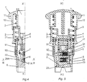
- la figure 4 est une demi-coupe selon IV-IV de la figure 1 ;
- la figure 5 est un coupe axiale d'une variante sans serrure de la tête illustrée à la figure 1.
Claims (6)
- Interrupteur du type bouton-poussoir comportant des contacts électriques actionnés par une tête constituée par un bouton de commande (1) associé à un corps (2) dans lequel se logent un piston (4) et un poussoir (6) de manoeuvre des contacts électriques qui sont susceptibles de coulisser et pivoter dans le corps (2) selon un axe (X-X') sans pouvoir pivoter relativement l'un par rapport à l'autre, le poussoir (6) étant équipé d'un premier verrou (7) et d'un second verrou (8), caractérisé par le fait que le piston (4) est pourvu d'un organe de commande (41) susceptible, lorsque le bouton (1) est poussé, d'actionner le premier verrou (7) dit d'arrêt immobilisant le poussoir (6) en position 〈〈 repos 〉〉 et de libérer alors le poussoir (6) qui peut venir en position d'accrochage où il est immobilisé par le second verrou (8) servant à l'accrochage.
- Interrupteur selon la revendication 1, caractérisé par le fait que le poussoir de commande (6) présente des moyens de guidage (61A et 61B) qui sont guidés sur des rampes hélicoïdales (28A et 28B) ménagées dans le corps (2).
- Interrupteur selon la revendication 2, caractérisé par le fait qu'il comporte un ressort d'armement (5) monté de manière à être comprimé entre le piston (4) et le poussoir (5).
- Interrupteur selon la revendication 1 ou 2, caractérisé par le fait que le corps (2) présente une rampe (27A) servant au recul du verrou (8) lorsque le poussoir pivote autour de son axe de rotation (X-X') et un bossage (27B) permettant une indexation du poussoir (6) et du piston (4) en position de déclenchement.
- Interrupteur selon l'une quelconque des revendications précédentes, caractérisé par le fait que le verrou d'accrochage (8) est enfoncé en position 〈〈 repos 〉〉 et, après libération du poussoir (6), vient immobiliser ce dernier en position d'accrochage.
- Interrupteur selon la revendication 1, caractérisé par le fait que le bouton de commande (1) reçoit, dans un logement, un barillet de serrure tournant (93) à clé relié en rotation et en translation au piston (4).
Applications Claiming Priority (2)
| Application Number | Priority Date | Filing Date | Title |
|---|---|---|---|
| FR9905069A FR2792453B1 (fr) | 1999-04-16 | 1999-04-16 | Interrupteur de type bouton-poussoir pour arret d'urgence |
| FR9905069 | 1999-04-16 |
Publications (2)
| Publication Number | Publication Date |
|---|---|
| EP1045411A1 true EP1045411A1 (fr) | 2000-10-18 |
| EP1045411B1 EP1045411B1 (fr) | 2004-06-02 |
Family
ID=9544718
Family Applications (1)
| Application Number | Title | Priority Date | Filing Date |
|---|---|---|---|
| EP00400994A Expired - Lifetime EP1045411B1 (fr) | 1999-04-16 | 2000-04-11 | Interrupteur de type bouton-poussoir pour arrêt d'urgence |
Country Status (5)
| Country | Link |
|---|---|
| US (1) | US6501037B2 (fr) |
| EP (1) | EP1045411B1 (fr) |
| DE (1) | DE60011180T2 (fr) |
| ES (1) | ES2218080T3 (fr) |
| FR (1) | FR2792453B1 (fr) |
Families Citing this family (16)
| Publication number | Priority date | Publication date | Assignee | Title |
|---|---|---|---|---|
| FR2874738B1 (fr) * | 2004-08-25 | 2006-10-27 | Schneider Electric Ind Sas | Bouton d'arret d'urgence |
| TWD112193S1 (zh) | 2004-10-23 | 2006-08-01 | 南柯有限公司 | 具有彈起球形把手之彈簧鎖 |
| USD537317S1 (en) * | 2004-10-23 | 2007-02-27 | Southco, Inc. | Pop-up knob |
| USD546661S1 (en) * | 2004-10-23 | 2007-07-17 | Southco, Inc. | Slam latch with pop-up knob |
| TW200619480A (en) * | 2004-10-23 | 2006-06-16 | Southco | Slam latch with pop-up knob |
| US9273487B2 (en) * | 2006-12-21 | 2016-03-01 | United States Postal Service | High-strength lock, method of making high-strength lock, and method for mounting high-strength lock |
| CN101217083B (zh) * | 2008-01-11 | 2011-06-15 | 友达光电(苏州)有限公司 | 分体式紧急停机操作装置 |
| US8084701B1 (en) | 2009-06-05 | 2011-12-27 | The Eastern Company | Push button actuator |
| FR2971358B1 (fr) * | 2011-02-08 | 2013-07-26 | Schneider Electric Ind Sas | Dispositif de commutation sans-fil |
| FR2974232A1 (fr) * | 2011-04-18 | 2012-10-19 | Schneider Electric Ind Sas | Dispositif d'arret d'urgence |
| US9728351B2 (en) | 2013-11-27 | 2017-08-08 | The Eastern Company | Electrical switch operated by lockable push button actuator, and retrofit method and kit |
| USD747175S1 (en) * | 2014-09-11 | 2016-01-12 | ApexOEM, Inc. | Thumb turn latch |
| FR3066042A1 (fr) * | 2017-05-02 | 2018-11-09 | Schneider Electric Industries Sas | Dispositif d'arret d'urgence |
| CN108133854B (zh) * | 2017-12-22 | 2019-05-21 | 安徽昱和自动化科技有限公司 | 一种急停后锁死防误操作急停按钮 |
| DE102018212701A1 (de) * | 2018-07-30 | 2020-01-30 | D. la Porte Söhne GmbH | Selbstverriegelnder Druckknopf |
| CA3118366A1 (fr) * | 2018-11-09 | 2020-05-14 | Linak A/S | Arret d'urgence |
Citations (4)
| Publication number | Priority date | Publication date | Assignee | Title |
|---|---|---|---|---|
| FR2521768A1 (fr) * | 1982-02-12 | 1983-08-19 | Telemecanique Electrique | Dispositif d'arret d'urgence |
| EP0172926A1 (fr) * | 1984-08-23 | 1986-03-05 | Square D Starkstrom GmbH | Adaptateur de manoeuvre pour dispositifs de commande ou de signalisation, en particulier interrupteur d'arrêt d'urgence |
| GB2169142A (en) * | 1984-12-28 | 1986-07-02 | Telemecanique Electrique | Switches |
| DE3608569A1 (de) * | 1986-03-14 | 1987-09-17 | Bbc Brown Boveri & Cie | Betaetigungselement mit einem betaetigungsstoessel fuer explosionsgeschuetztes elektrisches schaltgeraet |
Family Cites Families (1)
| Publication number | Priority date | Publication date | Assignee | Title |
|---|---|---|---|---|
| FR2631067B1 (fr) * | 1988-05-04 | 1991-02-08 | Neiman Sa | Verrou a rotor debrayable |
-
1999
- 1999-04-16 FR FR9905069A patent/FR2792453B1/fr not_active Expired - Fee Related
-
2000
- 2000-04-11 DE DE60011180T patent/DE60011180T2/de not_active Expired - Lifetime
- 2000-04-11 ES ES00400994T patent/ES2218080T3/es not_active Expired - Lifetime
- 2000-04-11 EP EP00400994A patent/EP1045411B1/fr not_active Expired - Lifetime
- 2000-04-14 US US09/550,335 patent/US6501037B2/en not_active Expired - Lifetime
Patent Citations (4)
| Publication number | Priority date | Publication date | Assignee | Title |
|---|---|---|---|---|
| FR2521768A1 (fr) * | 1982-02-12 | 1983-08-19 | Telemecanique Electrique | Dispositif d'arret d'urgence |
| EP0172926A1 (fr) * | 1984-08-23 | 1986-03-05 | Square D Starkstrom GmbH | Adaptateur de manoeuvre pour dispositifs de commande ou de signalisation, en particulier interrupteur d'arrêt d'urgence |
| GB2169142A (en) * | 1984-12-28 | 1986-07-02 | Telemecanique Electrique | Switches |
| DE3608569A1 (de) * | 1986-03-14 | 1987-09-17 | Bbc Brown Boveri & Cie | Betaetigungselement mit einem betaetigungsstoessel fuer explosionsgeschuetztes elektrisches schaltgeraet |
Also Published As
| Publication number | Publication date |
|---|---|
| EP1045411B1 (fr) | 2004-06-02 |
| FR2792453A1 (fr) | 2000-10-20 |
| DE60011180D1 (de) | 2004-07-08 |
| US20020134656A1 (en) | 2002-09-26 |
| DE60011180T2 (de) | 2005-06-09 |
| FR2792453B1 (fr) | 2001-05-11 |
| US6501037B2 (en) | 2002-12-31 |
| ES2218080T3 (es) | 2004-11-16 |
Similar Documents
| Publication | Publication Date | Title |
|---|---|---|
| EP1045411B1 (fr) | Interrupteur de type bouton-poussoir pour arrêt d'urgence | |
| EP1710456B1 (fr) | Mousqueton à verrouillage automatique | |
| EP0826890B1 (fr) | Mousqueton à verrou | |
| FR2645626A1 (fr) | Briquet a gaz | |
| FR2672554A1 (fr) | Frein a main de stationnement pour vehicule automobile et procede de fabrication du levier de ce frein. | |
| FR2919196A1 (fr) | Descendeur autobloquant a poignee debrayable. | |
| FR2952956A1 (fr) | Cle a insert escamotable a resistance mecanique amelioree | |
| FR2912543A1 (fr) | Commutateur a verrouillage | |
| FR3090719A1 (fr) | Commande d’ouverture à remontage mécanique. | |
| EP3670798A1 (fr) | Commande d'ouverture a remontage mecanique | |
| FR2629258A1 (fr) | Dispositif d'arret d'urgence a commande par cable | |
| FR2575590A1 (fr) | Appareil interrupteur d'urgence | |
| EP2565353B1 (fr) | Dispositif de verrouillage et de déverrouillage à l'aide d'une clé d'un tampon sur un cadre à bouchon intégré de fermeture d'une ouverture du tampon pour le passage de la clé | |
| EP2615313A1 (fr) | Dispositif de connexion mécanique pour relier une charge à un support | |
| FR2765611A1 (fr) | Dispositif d'ouverture d'une serrure de vehicule | |
| FR2692559A1 (fr) | Dispositif de sécurité pour récipient de conditionnement muni d'un organe de distribution comportant une tige de manÓoeuvre. | |
| EP0305485A1 (fr) | Serrure a mecanisme de verrouillage-deverrouillage a l'aide d'un electro-aimant. | |
| FR2971536A1 (fr) | Dispositif de commande de l'ouverture interieure d'un ouvrant a bouton poussoir et tendeur de cable. | |
| FR2874738A1 (fr) | Bouton d'arret d'urgence | |
| EP0800189B1 (fr) | Dispositif d'actionnement pour appareil électrique tel que disjoncteur-moteur | |
| WO2019077219A1 (fr) | Vehicule comprenant un dispositif de verrouillage d'ouvrant integrant la commande d'ouverture dudit ouvrant | |
| EP0352176B1 (fr) | Dispositif de verrouillage d'un boîtier avec couvercle formant par example vide-poches pour véhicule automobile | |
| FR2690890A1 (fr) | Dispositif antivol pour véhicule agissant sur l'embrayage. | |
| FR2853293A1 (fr) | Dispositif de commande de frein de service | |
| EP0091360B1 (fr) | Commande mécanique à distance pour moteurs électriques antidéflagrants |
Legal Events
| Date | Code | Title | Description |
|---|---|---|---|
| PUAI | Public reference made under article 153(3) epc to a published international application that has entered the european phase |
Free format text: ORIGINAL CODE: 0009012 |
|
| AK | Designated contracting states |
Kind code of ref document: A1 Designated state(s): DE ES GB IT |
|
| AX | Request for extension of the european patent |
Free format text: AL;LT;LV;MK;RO;SI |
|
| 17P | Request for examination filed |
Effective date: 20001102 |
|
| AKX | Designation fees paid |
Free format text: DE ES GB IT |
|
| RAP1 | Party data changed (applicant data changed or rights of an application transferred) |
Owner name: SCHNEIDER ELECTRONIC INDUSTRIES SAS |
|
| RAP1 | Party data changed (applicant data changed or rights of an application transferred) |
Owner name: SCHNEIDER ELECTRIC INDUSTRIES SAS |
|
| GRAP | Despatch of communication of intention to grant a patent |
Free format text: ORIGINAL CODE: EPIDOSNIGR1 |
|
| RIN1 | Information on inventor provided before grant (corrected) |
Inventor name: GRESSIER, ALAIN Inventor name: GENDRE, MICHEL |
|
| GRAS | Grant fee paid |
Free format text: ORIGINAL CODE: EPIDOSNIGR3 |
|
| RIN1 | Information on inventor provided before grant (corrected) |
Inventor name: GENDRE, MICHEL Inventor name: GRESSIER, ALAIN |
|
| GRAA | (expected) grant |
Free format text: ORIGINAL CODE: 0009210 |
|
| AK | Designated contracting states |
Kind code of ref document: B1 Designated state(s): DE ES GB IT |
|
| REG | Reference to a national code |
Ref country code: GB Ref legal event code: FG4D Free format text: NOT ENGLISH |
|
| RIN1 | Information on inventor provided before grant (corrected) |
Inventor name: GENDRE, MICHEL Inventor name: GRESSIER, ALAIN |
|
| REF | Corresponds to: |
Ref document number: 60011180 Country of ref document: DE Date of ref document: 20040708 Kind code of ref document: P |
|
| GBT | Gb: translation of ep patent filed (gb section 77(6)(a)/1977) |
Effective date: 20040823 |
|
| REG | Reference to a national code |
Ref country code: ES Ref legal event code: FG2A Ref document number: 2218080 Country of ref document: ES Kind code of ref document: T3 |
|
| PLBE | No opposition filed within time limit |
Free format text: ORIGINAL CODE: 0009261 |
|
| STAA | Information on the status of an ep patent application or granted ep patent |
Free format text: STATUS: NO OPPOSITION FILED WITHIN TIME LIMIT |
|
| 26N | No opposition filed |
Effective date: 20050303 |
|
| PGFP | Annual fee paid to national office [announced via postgrant information from national office to epo] |
Ref country code: ES Payment date: 20150423 Year of fee payment: 16 Ref country code: DE Payment date: 20150325 Year of fee payment: 16 Ref country code: GB Payment date: 20150414 Year of fee payment: 16 |
|
| PGFP | Annual fee paid to national office [announced via postgrant information from national office to epo] |
Ref country code: IT Payment date: 20150423 Year of fee payment: 16 |
|
| REG | Reference to a national code |
Ref country code: DE Ref legal event code: R119 Ref document number: 60011180 Country of ref document: DE |
|
| GBPC | Gb: european patent ceased through non-payment of renewal fee |
Effective date: 20160411 |
|
| PG25 | Lapsed in a contracting state [announced via postgrant information from national office to epo] |
Ref country code: DE Free format text: LAPSE BECAUSE OF NON-PAYMENT OF DUE FEES Effective date: 20161101 Ref country code: GB Free format text: LAPSE BECAUSE OF NON-PAYMENT OF DUE FEES Effective date: 20160411 |
|
| PG25 | Lapsed in a contracting state [announced via postgrant information from national office to epo] |
Ref country code: IT Free format text: LAPSE BECAUSE OF NON-PAYMENT OF DUE FEES Effective date: 20160411 |
|
| PG25 | Lapsed in a contracting state [announced via postgrant information from national office to epo] |
Ref country code: ES Free format text: LAPSE BECAUSE OF NON-PAYMENT OF DUE FEES Effective date: 20160412 |
|
| REG | Reference to a national code |
Ref country code: ES Ref legal event code: FD2A Effective date: 20181130 |