EP1044155B1 - Dispositif pour modifier la position d'articles achemines dans un courant a recouvrement - Google Patents
Dispositif pour modifier la position d'articles achemines dans un courant a recouvrement Download PDFInfo
- Publication number
- EP1044155B1 EP1044155B1 EP98960985A EP98960985A EP1044155B1 EP 1044155 B1 EP1044155 B1 EP 1044155B1 EP 98960985 A EP98960985 A EP 98960985A EP 98960985 A EP98960985 A EP 98960985A EP 1044155 B1 EP1044155 B1 EP 1044155B1
- Authority
- EP
- European Patent Office
- Prior art keywords
- conveyor
- objects
- drive
- conveying speed
- displacement
- Prior art date
- Legal status (The legal status is an assumption and is not a legal conclusion. Google has not performed a legal analysis and makes no representation as to the accuracy of the status listed.)
- Expired - Lifetime
Links
Images

Classifications
-
- B—PERFORMING OPERATIONS; TRANSPORTING
- B65—CONVEYING; PACKING; STORING; HANDLING THIN OR FILAMENTARY MATERIAL
- B65H—HANDLING THIN OR FILAMENTARY MATERIAL, e.g. SHEETS, WEBS, CABLES
- B65H29/00—Delivering or advancing articles from machines; Advancing articles to or into piles
- B65H29/66—Advancing articles in overlapping streams
- B65H29/669—Advancing articles in overlapping streams ending an overlapping stream
-
- B—PERFORMING OPERATIONS; TRANSPORTING
- B65—CONVEYING; PACKING; STORING; HANDLING THIN OR FILAMENTARY MATERIAL
- B65H—HANDLING THIN OR FILAMENTARY MATERIAL, e.g. SHEETS, WEBS, CABLES
- B65H29/00—Delivering or advancing articles from machines; Advancing articles to or into piles
- B65H29/66—Advancing articles in overlapping streams
- B65H29/6654—Advancing articles in overlapping streams changing the overlapping figure
-
- B—PERFORMING OPERATIONS; TRANSPORTING
- B65—CONVEYING; PACKING; STORING; HANDLING THIN OR FILAMENTARY MATERIAL
- B65H—HANDLING THIN OR FILAMENTARY MATERIAL, e.g. SHEETS, WEBS, CABLES
- B65H5/00—Feeding articles separated from piles; Feeding articles to machines
- B65H5/24—Feeding articles in overlapping streams, i.e. by separation of articles from a pile
-
- B—PERFORMING OPERATIONS; TRANSPORTING
- B65—CONVEYING; PACKING; STORING; HANDLING THIN OR FILAMENTARY MATERIAL
- B65H—HANDLING THIN OR FILAMENTARY MATERIAL, e.g. SHEETS, WEBS, CABLES
- B65H2301/00—Handling processes for sheets or webs
- B65H2301/40—Type of handling process
- B65H2301/44—Moving, forwarding, guiding material
- B65H2301/447—Moving, forwarding, guiding material transferring material between transport devices
- B65H2301/4471—Grippers, e.g. moved in paths enclosing an area
- B65H2301/44712—Grippers, e.g. moved in paths enclosing an area carried by chains or bands
-
- B—PERFORMING OPERATIONS; TRANSPORTING
- B65—CONVEYING; PACKING; STORING; HANDLING THIN OR FILAMENTARY MATERIAL
- B65H—HANDLING THIN OR FILAMENTARY MATERIAL, e.g. SHEETS, WEBS, CABLES
- B65H2301/00—Handling processes for sheets or webs
- B65H2301/40—Type of handling process
- B65H2301/44—Moving, forwarding, guiding material
- B65H2301/447—Moving, forwarding, guiding material transferring material between transport devices
- B65H2301/4473—Belts, endless moving elements on which the material is in surface contact
- B65H2301/44732—Belts, endless moving elements on which the material is in surface contact transporting articles in overlapping stream
-
- B—PERFORMING OPERATIONS; TRANSPORTING
- B65—CONVEYING; PACKING; STORING; HANDLING THIN OR FILAMENTARY MATERIAL
- B65H—HANDLING THIN OR FILAMENTARY MATERIAL, e.g. SHEETS, WEBS, CABLES
- B65H2511/00—Dimensions; Position; Numbers; Identification; Occurrences
- B65H2511/20—Location in space
- B65H2511/22—Distance
Definitions
- the present invention relates to a device for changing the position of flexible, resulting in a shingled stream on a first conveyor flat objects, in particular printed products, according to the preamble of claim 1.
- a device of this type is known from CH Patent No. 677 778.
- a position changing device between the conveyor belts forming a conveyor level arranged. It has two side by side in the funding level arranged, oppositely driven discs on which Eccentrically there is a sliding cam.
- These shift cams are destined for this, in each case in a stream of scales at the rear edge to get into the system on the first conveyor, accelerate it in the direction of conveyance and feed it to the second conveyor.
- a braking device is assigned to this, which is intended for this purpose is the objects accelerated by the rotation of the discs to slow down the conveyor speed of the second conveyor.
- the one with this Device especially associated with large processing capacity high speeds and delays represent a significant Stress on the objects and can lead to injuries. Furthermore, to achieve a certain target distance of the objects on the second conveyor the distance of the sliding cams from the Axes of rotation of the disks and the speed of rotation of the disks from each other as also from the conveyor speeds of the first and second conveyor, the target distance and the distance of the objects in the resulting Scale formation dependent, which is why the applicability tighter There are limits.
- Another device is disclosed in WO 95/03989 known in the printing products from a first to a second Funders are transferred.
- the second conveyor has a chain on which Transport clamps are firmly attached at the same distance from each other.
- the Transport clips are therefore periodically used at a transfer point a printed product.
- a position change device is for this concerned that the printed products at the right time at the second conveyor arrives.
- the requirements for the first sponsor and the previous conveyor systems are therefore very high, so that at Irregularities in the feed can easily lead to malfunctions.
- the device known type in such a way that with gentle treatment of the Objects can be used more universally.
- Preferred embodiments of the device are in the dependent ones Claims specified.
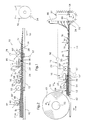
- the device 10 shown in FIG. 1 has a first belt conveyor 12 driven in the conveying direction F with a first conveying speed v 1 . This is immediately followed by a second belt conveyor 14 which is driven in the conveying direction F with a second conveying speed v 2 which is greater than the first conveying speed v 1 .
- a position change device 16 is arranged above the first belt conveyor 12. It has a hook-shaped displacement means 18, which can be moved in and against the conveying direction F along a rectilinear movement path 24 by means of a drive 22 designed as a cylinder-piston unit 20.
- the cylinder-piston unit 20 is, as indicated by dashed lines, connected to a control device 26 which is influenced by the conveying speed v 2 of the second belt conveyor 14.
- the distance between the rear edges 30 of successive objects 28 is denoted by A 1 .
- the position change device 16 is intended to engage with the sliding means 18 on the rear edge 30 of each object 28 fed by the first belt conveyor 12 in a form-fitting manner and to feed it in the conveying direction F to the second belt conveyor 14 such that the rear edges 30 of successive objects 28 in the scale formation S 2 by one Desired distance A 2 are spaced apart.
- the drive 22 is operated at a frequency f, which is given by the quotient of the second conveying speed v 2 and the target distance A 2 .
- the displacement means 18 is accelerated to a speed v in a short acceleration section of the movement path 24, which corresponds to the second conveying speed v 2 , then moved further at this speed in a movement path section 24 ′ and braked in a braking section that is again short.
- the downstream end of the movement path section 24 ' is arranged at a distance from the second belt conveyor 14 such that the object 28 supplied by the position changing device 16 is carried along by the second belt conveyor 14 when the displacement means enters the braking section.
- a second conveyor 32 is connected downstream of the second belt conveyor 14, as indicated by dash-dotted lines. It has transport brackets 34 arranged one behind the other, which are intended to take an object 28 from the second belt conveyor 14 and to convey it away.
- the second conveying speed v 2 , the desired distance A 2 and the phase position of the objects 28 on the second belt conveyor 14 - and thus the position changing device 16 - are matched to the conveyor 32 in such a way that an object 28 is fed to each transport clamp 34.
- a counter 36 Upstream of the position change device 16 is above the first Belt conveyor 12 arranged a counter 36.
- a counting organ 40 which is intended to attach itself the trailing edge 30 of each object 28 to apply to each object 28 to deliver a count signal to a counter.
- a pressure roller 39 prevents objects moving in the conveying direction from the counter organ 40 28 at most the trailing object due to friction can take with you.
- Particularly preferred forms of training of the counting device 36 are published in the international patent applications publication no. WO 99/35612, WO 99/35613 and WO 99/35614 - these are based on the CH patent applications, No. 1997 2983/97, 1997 2984/97 and 1997 2985 / 97-. The disclosure of these applications be incorporated into the available documents.
- a feed conveyor 42 which is also designed as a belt conveyor, is connected upstream of the first belt conveyor 12.
- a device 44 for pulling apart the objects 28 which occur in a narrowed, scale-like formation S o on the feed conveyor 42.
- a pushing element 48 which is arranged on a pushing drive 46 and is intended to be located on the rear edge 30 of each in the scale-like formation S o feed object 28 and feed it to the first belt conveyor 12 at a higher speed than the conveying speed v o of the feed conveyor 42.
- a weight roller 39 'prevents the trailing object 28 from being carried along by friction.
- the conveying speed v o of the feed conveyor 42 is lower than the conveying speed v 1 of the first belt conveyor 12.
- weight rollers 50 and 50 ′ act with these belt conveyors in the upstream starting area. together.
- Another preferred embodiment of the device 44 is disclosed in Swiss Patent Application No. 1997 2983/97 and in the corresponding WO 99/35612.
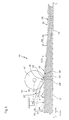
- the device shown in Fig. 1 operates as follows. With the position change device 16 synchronized with the displacement conveyor 32 and the synchronized second belt conveyor 14, a drive unit 52 for the first belt conveyor 12 is set in such a way that each object 28 is detected individually by means of the displacement means 18 and is supplied to the second belt conveyor 14 in the correct phase and at the required distance A 2 .
- the feed conveyor 42, the counting device 36 and the device 44 are matched to the speed of the drive unit 52, which ensures that the objects 28 occurring in the scale-like formation S o are pushed apart and counted at least to the necessary distance A 1 .
- the displacement means 18 has two displacement elements 18 'driven in push-pull.
- the control device 26 controls the drive 22 of the displacement elements 18 'in such a way that in time with the second belt conveyor - this is given by the quotient of the desired distance A 2 and the second conveying speed v 2 - one displacement element 18' at the downstream end of the Movement path section 24 'is located.
- Each displacement element 18 ' is assigned a sensor element 54 which, when the respective displacement element 18' interacts with the rear edge 30 of an object 28, emits a signal to a counter 56 and to a release device 58 of the displacement conveyor 32 connected downstream of the second belt conveyor 14.
- the first belt conveyor 12 is in turn connected upstream of a feed conveyor 42, the conveying speed v o of which corresponds to the conveying speed v 1 of the first belt conveyor 12. This lies underneath on a winding 60.
- the objects 28, which are wound together with a winding tape under tension, are wound onto a winding core 62 in a narrowed, scale-like formation S o . Seen in the unwinding direction W, in the scale-like formation S o each object lies on the trailing one with a small distance A o between the rear edges 30.
- the drive unit 52 for the first belt conveyor 12, the feed conveyor 42 and the winding 60 is matched to the drive 22 of the position changing device 16 such that the displacement power of the position changing device 16 is approximately 20% greater than the power with which the objects 28 of the position changing device 16 be fed. Since the displacement elements 18 'are driven at a higher frequency than the objects 28, each displacement element 18' does not move an object 28 into the effective range of the second belt conveyor 14 with each conveying stroke in the conveying direction F. This causes missing objects 28 in the scale stream S 2 Gaps L, but as a result of the synchronization between the second belt conveyor 14 and the position changing device 16 it is ensured that the distance between the trailing edges 30 of successive objects 28 always corresponds to the target distance A 2 or an integral multiple thereof.
- the conveyor 32 has individually movable transport clamps 34 arranged one behind the other in a guide 66.
- the guide 66 runs around a drive wheel 70 which, as indicated by dash-dotted lines, is drive-coupled to the second belt conveyor 14.
- the drive wheel 70 has entrainment members for the transport clips 34 on the circumference at regular intervals.
- the release device 58 is directly upstream of the drive wheel 70. Since the release device 58 only releases a transport clamp 34 in response to a signal from the counter 56, it is ensured that an object 28 is fed to each transport clamp 34.
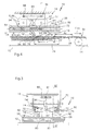
- a particularly preferred embodiment of the position change device 16, as used with advantage in the device shown in FIG. 2 is shown in Figs. 3 and 4. It has two parallel in the conveying direction F guide rails 72.
- Guide rail 72 In every Guide rail 72 is a slide 74 out on which a self-resilient trained, for example made of spring steel sliding element 18 'is attached at one end. That in the direction of conveyance F above that Carriage 74 projecting displacement element 18 'is in its free, leading end region formed as a piercing tongue 76, which its side facing away from the first belt conveyor 12 with a reflector element 78 is provided.
- the displacement element 18 ' At the end of the carriage 74 facing Grooving tongue 76, the displacement element 18 'has a sliding cam 80 on.
- each reflector element 78 and thus of the displacement element 18 ' is a light source light sensor unit connected to counter 56 (FIG. 2) 82 arranged in a fixed position. Is the reflector element 78 of covered by an object 28 remains that of the light source light sensor unit 82 and the light barrier formed by the reflector element 78 are interrupted, which means that with the corresponding conveying stroke of the displacement element 18 'an object 28 is fed to the second belt conveyor 14 becomes. However, if the light barrier is not interrupted, this means that the displacement element 18 'does not move an object 28.
- the drive 22 for the displacement elements 18 ' has a self-contained pulling element 84, for example formed by a chain. It is guided around two deflection wheels 86 in such a way that the conveying strand 84 ′ extends between the guide rails 72 in the conveying direction F. Driving cams 88 mutually protrude from the pulling element 84 at the desired distance A 2 for the objects 28.
- the driving cams 88 When the traction element 84 is driven in the direction of rotation U, the driving cams 88 come into contact with the upstream end face 74 'of the slides 74 which are in the rest position 90 and take them along in the conveying direction F until the end of the movement path 24 is reached, where the driving cams 88 as a result of the deflection around the downstream deflection wheel 86 from the end face 74 '.
- the speed v at which the driving cams 88 are driven corresponds to the second conveying speed v 2 .
- the carriage 74 In the acceleration section of the movement path 24 between the rest position 90 of the carriage 74, in which they are held by means of a tension spring 92 and the position of the axis of the upstream deflection wheel 86, the carriage 74 is accelerated to the second conveying speed v 2 .
- the movement path section 24 ' which extends over a length corresponding to the distance between the axes of the two deflection wheels 86, it maintains this speed.
- the carriage 74 is decelerated from the position of the axis of the downstream deflection wheel 86 to the end of the driving cam 88 in question on the end face 74 ', which slides back into the rest position 90 as a result of the force of the tension spring 92.
- the displacement elements 18 ' are not in the range of Objects 28 must be swung out, making a very exact positioning and transfer of the items to the second Belt conveyor 14 is guaranteed. Since the displacement elements 18 'in their Rest position and in their movement against the conveying direction F over Paint objects 28, they need for movement in the conveying direction and to act on the objects 28 not in their path of movement 24 to be swung in. They work with the objects 28 together in the manner of a freewheel. This leads to a safe one Taking every item with you.
- the length of the movement path section 24 ′ corresponds to the target distance A 2 , but it can also be different.
- the first conveying speed v 1 is matched to the second conveying speed v 2 in such a way that two objects 28 are definitely never grasped by the displacement elements 18 ′ and fed to the second belt conveyor 14.
- the side by side conveyor belts of the first belt conveyor 12 are made of rubber-elastic material so that they are present of objects 28 between themselves and one on the indentations 76 matched reference 96 can form a sag.
- the each object 28 to be gripped by a displacement element 18 ' thereby approximately parallel to the guide rails 72 and Conveying level of the second belt conveyor 14.
- the drive 22 is designed as a cylinder-piston unit 20, which is fixed at one end and is provided at the other with a displacement element 18 '.
- the cylinder-piston unit 20 is connected to a control device 26, which in turn is connected to a scanning device 94 for the trailing edges 30 of the objects 28 occurring in the scale formation S 1 on the first belt conveyor 12.
- the displacement element 18 ' is intended to rest on the flat side 28' of the objects 28.
- the control device 26 controls the cylinder-piston unit 20 as a function of the desired distance A 2 to be achieved, the second conveying speed v 2 and the signals from the scanning device 94.
- the movement path 24 is given by the flat side 28 'of the objects 28.
- a weight roller 50 ′ prevents the objects 28 located upstream with respect to the displacement element 18 ′ from being carried along.
- FIGS. 6 and 7 show a further embodiment of the position changing device 16, in which the displacement means 18 has twelve displacement elements 18 '.
- These are double lever-shaped and with their cross-sectionally U-shaped bearing part 19 are pivotally mounted on bearing shafts 100 projecting from a support disk 98.
- the bearing shafts 100 run parallel to a drive shaft 102, on which the support disk 98 is seated in a rotationally fixed manner, and are arranged on a circle which is concentric with the drive shaft and are uniformly distributed in the circumferential direction.
- the support disk 98 is driven to rotate in the direction of rotation D in a manner coordinated with the conveying speed v 2 of the second belt conveyor 14 connected downstream of the first belt conveyor 12.
- the bearing parts 19 of the displacement elements 18 'each carry a freely rotatably mounted follower roller 104.
- One end of a tension spring 108 engages on the bearing pin 106 of each follower roller 104, which, on the other hand, is fastened further inward to the support disk 98 when viewed in the radial direction.
- the tension springs 108 hold the follow rollers 104 on the circumference of a fixedly arranged control disk 110.
- the circumference of the control disk 110 forms a control link 112 for the pivoting position of the displacement elements 18 '.
- the control link 112 runs concentrically to the drive shaft 102.
- the corresponding displacement elements 18 assumee a position with respect to the circular support disk 98 , in which the hook-shaped end is trailing with respect to the follower roller 104 and the displacement elements 18 form an angle of approximately 45 ° to an associated tangent to the support disk 98.
- a link section 112 1 in which the distance to the drive shaft 112 increases continuously, begins approximately vertically below the drive shaft 102 in the direction of rotation D. This is followed by a section 112 2 of approximately the same length, in which the distance becomes smaller again.
- section 112 3 Immediately following is a section 112 3 , in which the distance increases again within a small angular range. In an area following section 112 3 , the distance again remains unchanged, which then decreases again in a range between approximately four and three o'clock and adapts to the radius of the concentric section.
- This form of the control link 112 has the following effect. If a follower roller 104 approaches section 112 1 of the control link, viewed in the direction of rotation D, the hook-shaped end of the displacement element 18 'moves between the hold-down elements 114 in the insertion section 114 "and comes with its free end to the flat side 28' of an object 28 located above As a result, the hook-shaped end of the displacement element 18 'is pushed back resiliently, but the tension spring 108 and the follower roller 104 abut against the control link 112. The start of the hold-down section 114' coincides approximately with the area at which the displacement element 18 ' comes into contact with the respective object 28.
- the section 112, the control link 112 has the result that the hook-shaped end of the displacement means 118 moves along the movement path section 24 ', which is at least approximately rectilinear and in the conveying direction F.
- the Ver displacement element 18 'clockwise Since the rotational speed of the hook-shaped end of the displacement element 18 'is greater than the first conveying speed v 1 , the displacement element 18' comes to rest against the rear edge 30 of the leading object 28 and takes it along in the conveying direction F.
- the relevant shift element 18 ' is pivoted counterclockwise, which means that on the one hand the hook-shaped end of the shift element 18' continues to be moved along the at least approximately linear movement path section 24 'and on the other hand the trailing hook-shaped end of the shift element 18 'experiences an acceleration seen in the conveying direction F.
- the hook-shaped end of the displacement element 18 ' is accelerated to the second conveying speed v 2 of the second conveyor 14, which has the consequence that the one in question Moving element 18 'in the conveying direction F object 28 is fed to the second conveyor at the desired second conveying speed v 2 and in the correct phase position.
- the third section 112 3 has the result that the displacement element 18 'is pivoted clockwise in order to move its hook-shaped trailing end in the radial direction inwards away from the rear edge 30 of the object 28 being advanced. This and the following section prevent the sliding element 18 'from acting further on objects 28.
- the distance A 2 to be achieved between the rear edges 30 of successive objects 28 in the scale formation S 2 formed is given by the distance between the displacement elements 18 'on the support disk 98.
- This type of training is characterized by particularly quiet running, even with a very large processing capacity.
- the hold-down elements 114 prevent the objects from being bent open 28 when attacking a displacement element 18 '. Further prevent on both sides of the first belt conveyor 12 arranged hold-down device 118 helps the side Bending open the objects 28.
- this form of training can also be one with the sliding elements 18 'cooperating detection device which a counting and / or control device each emits a signal when a Sliding element 18 'cooperates with an object 28.
- the frequency f with which the displacement means 18 are moved in the conveying direction F through the movement path 24 is preferably approximately 1.2 to 1.4 times as large as the quotient of the first conveying speed v 1 and one permissible minimum distance A 1 between the trailing edges 30 of successive objects in the resulting formation S o or S 1 .
- the second conveying speed v 2 is preferably at least approximately 2 to 4 times as large as the first conveying speed v 1 .
- the quotient of the second conveying speed v 2 and the target distance A 2 is greater than the quotient of the first conveying speed v 1 and the minimum distance A 1 in the formation S o or S 1 .
- the movement path section 24 ′ is preferably at least approximately 2 to 4 times as long as the permissible minimum distance A 1 between the trailing edges 30 of successive objects 28 in the resulting formation S o or S 1 .
- the device shown in FIG. 2 preferably in combination with the device shown in FIGS. 3 to 7, is suitable also for equipping every object with a transport clamp 34.
Landscapes
- Engineering & Computer Science (AREA)
- Mechanical Engineering (AREA)
- Separation, Sorting, Adjustment, Or Bending Of Sheets To Be Conveyed (AREA)
- Attitude Control For Articles On Conveyors (AREA)
- Feeding Of Articles By Means Other Than Belts Or Rollers (AREA)
- Control And Other Processes For Unpacking Of Materials (AREA)
- Vending Machines For Individual Products (AREA)
- Cookers (AREA)
Claims (10)
- Dispositif pour modifier la position d'articles (28) flexibles et plats, en particulier des produits d'imprimerie, acheminés dans un courant de recouvrement (S1 ; S0) et arrivant sur un premier convoyeur (12), avec un dispositif pour la modification de position (16), disposé dans la zone du premier convoyeur (12) et muni d'un moyen de translation (18) qui, à l'aide d'un entraínement (22), est entraíné au moins dans une section (24') de la voie de déplacement (24), en fonction du sens de transport (F) du premier convoyeur (12), à une vitesse (v) supérieure à la vitesse de transport (v1) du premier convoyeur (12) et qui est destiné à conduire par pression sur le bord postérieur (30) de celui-ci, chaque article (28) transporté dans le dispositif de modification de position (16) par le premier convoyeur (12), à un second convoyeur (14) situé directement en aval du premier convoyeur (12) et entraíné à une vitesse de transport (v2) supérieure à la vitesse de transport (v1) du premier convoyeur,
caractérisé en ce que la section (24') de la voie de déplacement est au moins approximativement rectiligne et s'étend au moins approximativement dans le sens du transport (F) et en ce que l'entraínement (22) entraíne le moyen de translation (18) sans décélération dans la section de la voie de déplacement à une vitesse (v) qui, au moins lors du transfert des articles (28) sur le second convoyeur (14), est au moins approximativement égale à la vitesse de transport (v2) du second convoyeur (14). - Dispositif selon la revendication 1, caractérisé en ce que l'entraínement (22) est réglé en fonction de la vitesse de transport (v2) du second convoyeur (14) et d'un écart désirée . (A2) entre les articles (28) sur le second convoyeur (14) et en ce qu'il est réglable en fonction du second convoyeur (14), en position de phase.
- Dispositif selon l'une quelconque des revendications 1 ou 2, caractérisé en ce qu'un organe d'entraínement (52) entraíne le premier convoyeur (12) de telle manière à ce que le quotient de la vitesse de transport (v2) du second convoyeur (14) et de l'écart désirée (A2) soit supérieur au quotient de la vitesse de transport (V1) du premier convoyeur (12) et d'un écart minimal (A1) entre les bords postérieurs (30) d'articles (28) consécutifs, dans le courant de recouvrement (S0, S1) qui arrive.
- Dispositif selon l'une quelconque des revendications 1 à 3, caractérisé en ce qu'un système de détection (78, 82) coopérant avec le moyen de translation (18) restitue un signal à un système de comptage et/ou de commande (56), chaque fois que le moyen de translation (18) coopère avec un article (28).
- Dispositif selon la revendication 4, caractérisé en ce qu'un convoyeur d'évacuation (32), muni de pinces de transport (34) pour les articles (28), placées les unes derrière les autres, est situé en aval du second convoyeur (14), en ce que les pinces de transport (34) peuvent être interrogées à un poste de validation (58), situé en amont du poste de réception (68), en ce qu'un entraínement pour les pinces de transport (34), synchronisé avec le second convoyeur, agit entre le poste de validation (58) et le poste de réception et en que la longueur du second convoyeur (14) et la longueur du convoyeur d'évacuation (32), entre le poste de validation (58) et le poste de réception (68) sont adaptées entre elles de manière à permettre une validation en fonction du signal.
- Dispositif selon l'une quelconque des revendications 1 à 5, caractérisé en ce que le dispositif pour la modification de position (16) présente un moyen de guidage (72) du moyen de translation (18), s'étendant dans le sens du transport (F), en ce que l'entraínement (22) présente un organe de traction sans fin (84,) entraíné de manière rotative à une vitesse au moins approximative à la vitesse de transport (v2) du second convoyeur (14) et muni d'éléments entraíneurs (80) coopérant dans le sens de transport (F) avec le moyen de translation (18) et disposés les uns derrière les autres avec un écart au moins approximatif à l'écart désirée (A2).
- Dispositif selon la revendication 6, caractérisé en ce que les moyens de translation (18) présentent au moins deux éléments de translation (18'), qui sont alternativement entraínés dans le sens du transport (F).
- Dispositif selon l'une quelconque des revendications 1 à 5, caractérisé en ce que le moyen de translation (18) présente plusieurs éléments de translation (18'), qui sont entraínés de manière rotative le long d'une trajectoire circulaire (98) et dont la position est commandée de manière à ce qu'ils se déplacent le long de la section de voie de déplacement (24') au moins approximativement rectiligne et qui s'étend au moins approximativement dans le sens du transport (F).
- Dispositif pour le transfert d'articles (28), en particulier des produits d'imprimerie minces, d'un premier convoyeur (14) sur un second convoyeur (32), muni de pinces de transport, équipé d'un dispositif pour la modification de position (16) synchronisé avec le premier et le second convoyeur (14, 32) et permettant de synchroniser les articles (28) avec les pinces de transport (34) prévues pour le transfert,
caractérisé en ce que les pinces de transport (34) peuvent être interrogées séparément, conduites à un poste d'équipement (68), munies d'un article (28), accouplées avec un élément d'entraínement (66) prévu pour le transport d'évacuation des articles (28) et en ce que le dispositif de modification de position (16) est adapté pour détecter les articles (28) qui arrivent, pour les disposer un à un, en respectant la phase sur le premier convoyeur (14) et pour commander le second convoyeur (32) de manière à ce que le second convoyeur (32) prépare en temps utiles une pince de transport (34) pour chaque article (28) déposé sur le premier convoyeur (14). - Dispositif selon la revendication 9, caractérisé en ce que le second convoyeur (32) présente un entraínement synchronisé avec le premier convoyeur (14) et permettant de conduire individuellement après leur validation par le dispositif de modification de position (16) les pinces de transport (34) individuellement mobiles, situées en grand nombre l'une derrière l'autre dans un poste de validation (58) vers le poste d'équipement (68) où elles seront munies d'un article.
Applications Claiming Priority (3)
| Application Number | Priority Date | Filing Date | Title |
|---|---|---|---|
| CH298697 | 1997-12-30 | ||
| CH298697 | 1997-12-30 | ||
| PCT/CH1998/000561 WO1999035072A1 (fr) | 1997-12-30 | 1998-12-29 | Dispositif pour modifier la position d'articles achemines dans un courant a recouvrement |
Publications (2)
| Publication Number | Publication Date |
|---|---|
| EP1044155A1 EP1044155A1 (fr) | 2000-10-18 |
| EP1044155B1 true EP1044155B1 (fr) | 2002-05-08 |
Family
ID=4246091
Family Applications (1)
| Application Number | Title | Priority Date | Filing Date |
|---|---|---|---|
| EP98960985A Expired - Lifetime EP1044155B1 (fr) | 1997-12-30 | 1998-12-29 | Dispositif pour modifier la position d'articles achemines dans un courant a recouvrement |
Country Status (11)
| Country | Link |
|---|---|
| US (1) | US6554125B1 (fr) |
| EP (1) | EP1044155B1 (fr) |
| JP (1) | JP2002500149A (fr) |
| AT (1) | ATE217292T1 (fr) |
| AU (1) | AU740546B2 (fr) |
| CA (1) | CA2310809C (fr) |
| DE (1) | DE59804099D1 (fr) |
| DK (1) | DK1044155T3 (fr) |
| ES (1) | ES2173655T3 (fr) |
| RU (1) | RU2194002C2 (fr) |
| WO (1) | WO1999035072A1 (fr) |
Families Citing this family (4)
| Publication number | Priority date | Publication date | Assignee | Title |
|---|---|---|---|---|
| DE50007436D1 (de) | 1999-06-01 | 2004-09-23 | Ferag Ag | Vorrichtung zum Korrigieren der Lage von geschuppt anfallenden flächigen Gegenständen |
| DE102009025611B4 (de) * | 2008-07-11 | 2022-08-25 | Heidelberger Druckmaschinen Ag | Verfahren und Vorrichtung zum Zuführen von Bogen zu einer Verarbeitungsmaschine |
| CN108221193B (zh) * | 2018-03-22 | 2024-04-19 | 长沙学院 | 一种转动式多点张紧定位装置 |
| JP2022109817A (ja) * | 2021-01-15 | 2022-07-28 | 理想科学工業株式会社 | 給紙装置 |
Family Cites Families (9)
| Publication number | Priority date | Publication date | Assignee | Title |
|---|---|---|---|---|
| CH592562A5 (fr) * | 1974-05-28 | 1977-10-31 | Ferag Ag | |
| CH618398A5 (fr) * | 1977-06-06 | 1980-07-31 | Ferag Ag | |
| CH631410A5 (en) | 1978-08-17 | 1982-08-13 | Ferag Ag | Device for homogenising an imbricated stream formed from flat products, in particular printed products |
| CH637091A5 (de) * | 1979-01-29 | 1983-07-15 | Ferag Ag | Vorrichtung zum zufuehren von in einem schuppenstrom anfallenden flaechigen erzeugnissen, insbesondere druckprodukten, zu einem transporteur. |
| CH649264A5 (de) | 1980-12-11 | 1985-05-15 | Grapha Holding Ag | Einrichtung zum vergleichmaessigen eines schuppenstromes von druckbogen. |
| CH655488B (fr) * | 1982-03-11 | 1986-04-30 | ||
| DE3762033D1 (de) * | 1986-07-29 | 1990-05-03 | Ferag Ag | Vorrichtung zum vergleichmaessigen des abstandes zwischen aufeinanderfolgenden produkten einer schuppenformation. |
| CH677778A5 (fr) | 1988-03-14 | 1991-06-28 | Ferag Ag | |
| DK89993D0 (da) * | 1993-08-03 | 1993-08-03 | Thorsted Maskiner As | Fremgangsmaade og indretning til overfoering af skaeloplagte tryksager til en gribekaede |
-
1998
- 1998-12-29 CA CA002310809A patent/CA2310809C/fr not_active Expired - Fee Related
- 1998-12-29 AU AU16585/99A patent/AU740546B2/en not_active Ceased
- 1998-12-29 EP EP98960985A patent/EP1044155B1/fr not_active Expired - Lifetime
- 1998-12-29 US US09/582,118 patent/US6554125B1/en not_active Expired - Fee Related
- 1998-12-29 DE DE59804099T patent/DE59804099D1/de not_active Expired - Lifetime
- 1998-12-29 AT AT98960985T patent/ATE217292T1/de not_active IP Right Cessation
- 1998-12-29 ES ES98960985T patent/ES2173655T3/es not_active Expired - Lifetime
- 1998-12-29 JP JP2000527486A patent/JP2002500149A/ja active Pending
- 1998-12-29 DK DK98960985T patent/DK1044155T3/da active
- 1998-12-29 WO PCT/CH1998/000561 patent/WO1999035072A1/fr active IP Right Grant
- 1998-12-29 RU RU2000120211/12A patent/RU2194002C2/ru not_active IP Right Cessation
Also Published As
| Publication number | Publication date |
|---|---|
| WO1999035072A1 (fr) | 1999-07-15 |
| DE59804099D1 (de) | 2002-06-13 |
| ES2173655T3 (es) | 2002-10-16 |
| RU2194002C2 (ru) | 2002-12-10 |
| AU1658599A (en) | 1999-07-26 |
| ATE217292T1 (de) | 2002-05-15 |
| EP1044155A1 (fr) | 2000-10-18 |
| CA2310809C (fr) | 2007-04-03 |
| US6554125B1 (en) | 2003-04-29 |
| CA2310809A1 (fr) | 1999-07-15 |
| DK1044155T3 (da) | 2002-07-08 |
| AU740546B2 (en) | 2001-11-08 |
| JP2002500149A (ja) | 2002-01-08 |
Similar Documents
| Publication | Publication Date | Title |
|---|---|---|
| EP0057810B1 (fr) | Appareil d'alimentation en pièces individuelles de matériau plat | |
| DE2822060C2 (fr) | ||
| EP0550828B1 (fr) | Procédé et dispositif de traitement de produits imprimés | |
| EP0309702B1 (fr) | Bande sans fin pour le transport d'articles | |
| DD287463A5 (de) | Einrichtung zum sammeln von gefalzten druckbogen | |
| EP0633212A1 (fr) | Dispositif de transport circulant sans fin pour charge isolée avec organes de transport individuels | |
| EP1479627B1 (fr) | Dispositif d'alignement de feuilles | |
| EP0259650B1 (fr) | Méthode et dispositif pour régulariser la distance séparant deux articles successifs d'un courant d'articles en écailles de poisson, notamment d'imprimés | |
| DE3108044C2 (de) | Vorrichtung zur Handhabung von Materialbogen | |
| DE3541594A1 (de) | Vorrichtung zum beschicken einer verarbeitungseinrichtung fuer biegsame, flaechige erzeugnisse, insbesondere druckprodukte | |
| EP0242702B1 (fr) | Procédé et dispositif pour tourner des objets plats | |
| EP1044155B1 (fr) | Dispositif pour modifier la position d'articles achemines dans un courant a recouvrement | |
| CH677778A5 (fr) | ||
| EP2055660B1 (fr) | Dispositif de retournement cadencé d'objets plats | |
| EP0893385B1 (fr) | Dispositif pour traiter des produits imprimés | |
| EP1124747A1 (fr) | Procede et dispositif d'alimentation en imprimes | |
| EP1072546B1 (fr) | Convoyeur pour assembler et traiter des produits imprimés | |
| EP0499691A1 (fr) | Procédé pour traiter des produits imprimés alimentés de façon continue en une formation imbriquée ainsi que dispositif pour la mise en oeuvre dudit procédé | |
| EP1988040B1 (fr) | Alimenteur de feuilles destiné à l'alimentation d'un dispositif de transport de feuilles d'impression pliées | |
| EP0216023B1 (fr) | Dispositif pour ordonner un courant d'articles se chevauchant | |
| EP0806391B1 (fr) | Dispositif pour l'alimentation de produits imprimés vers un autre poste de travail | |
| EP1059256B9 (fr) | Dispositif pour corriger la position d'objects plats arrivant en formation imbriquée | |
| EP1044154B1 (fr) | Dispositif pour transformer une pile d'objets recouvrants en une formation a recouvrement | |
| EP2418164B1 (fr) | Procédé et dispositif d'assemblage de produits plats avec d'autres produits plats et dispositif de transport de produits plats, notamment de produits d'imprimerie | |
| CH631410A5 (en) | Device for homogenising an imbricated stream formed from flat products, in particular printed products |
Legal Events
| Date | Code | Title | Description |
|---|---|---|---|
| PUAI | Public reference made under article 153(3) epc to a published international application that has entered the european phase |
Free format text: ORIGINAL CODE: 0009012 |
|
| 17P | Request for examination filed |
Effective date: 20000613 |
|
| AK | Designated contracting states |
Kind code of ref document: A1 Designated state(s): AT BE CH DE DK ES FI FR GB IT LI NL PT SE |
|
| GRAG | Despatch of communication of intention to grant |
Free format text: ORIGINAL CODE: EPIDOS AGRA |
|
| 17Q | First examination report despatched |
Effective date: 20010704 |
|
| GRAG | Despatch of communication of intention to grant |
Free format text: ORIGINAL CODE: EPIDOS AGRA |
|
| GRAG | Despatch of communication of intention to grant |
Free format text: ORIGINAL CODE: EPIDOS AGRA |
|
| GRAH | Despatch of communication of intention to grant a patent |
Free format text: ORIGINAL CODE: EPIDOS IGRA |
|
| REG | Reference to a national code |
Ref country code: GB Ref legal event code: IF02 |
|
| GRAH | Despatch of communication of intention to grant a patent |
Free format text: ORIGINAL CODE: EPIDOS IGRA |
|
| GRAA | (expected) grant |
Free format text: ORIGINAL CODE: 0009210 |
|
| AK | Designated contracting states |
Kind code of ref document: B1 Designated state(s): AT BE CH DE DK ES FI FR GB IT LI NL PT SE |
|
| REF | Corresponds to: |
Ref document number: 217292 Country of ref document: AT Date of ref document: 20020515 Kind code of ref document: T |
|
| REG | Reference to a national code |
Ref country code: CH Ref legal event code: EP |
|
| REG | Reference to a national code |
Ref country code: CH Ref legal event code: NV Representative=s name: PATENTANWAELTE SCHAAD, BALASS, MENZL & PARTNER AG |
|
| REF | Corresponds to: |
Ref document number: 59804099 Country of ref document: DE Date of ref document: 20020613 |
|
| REG | Reference to a national code |
Ref country code: DK Ref legal event code: T3 |
|
| PG25 | Lapsed in a contracting state [announced via postgrant information from national office to epo] |
Ref country code: PT Free format text: LAPSE BECAUSE OF FAILURE TO SUBMIT A TRANSLATION OF THE DESCRIPTION OR TO PAY THE FEE WITHIN THE PRESCRIBED TIME-LIMIT Effective date: 20020808 |
|
| GBT | Gb: translation of ep patent filed (gb section 77(6)(a)/1977) |
Effective date: 20020720 |
|
| ET | Fr: translation filed | ||
| REG | Reference to a national code |
Ref country code: ES Ref legal event code: FG2A Ref document number: 2173655 Country of ref document: ES Kind code of ref document: T3 |
|
| PG25 | Lapsed in a contracting state [announced via postgrant information from national office to epo] |
Ref country code: AT Free format text: LAPSE BECAUSE OF NON-PAYMENT OF DUE FEES Effective date: 20021229 |
|
| PG25 | Lapsed in a contracting state [announced via postgrant information from national office to epo] |
Ref country code: BE Free format text: LAPSE BECAUSE OF NON-PAYMENT OF DUE FEES Effective date: 20021231 |
|
| PLBE | No opposition filed within time limit |
Free format text: ORIGINAL CODE: 0009261 |
|
| STAA | Information on the status of an ep patent application or granted ep patent |
Free format text: STATUS: NO OPPOSITION FILED WITHIN TIME LIMIT |
|
| 26N | No opposition filed |
Effective date: 20030211 |
|
| BERE | Be: lapsed |
Owner name: *FERAG A.G. Effective date: 20021231 |
|
| PGFP | Annual fee paid to national office [announced via postgrant information from national office to epo] |
Ref country code: NL Payment date: 20041210 Year of fee payment: 7 |
|
| REG | Reference to a national code |
Ref country code: CH Ref legal event code: PFA Owner name: FERAG AG Free format text: FERAG AG#ZUERICHSTRASSE 74#8340 HINWIL (CH) -TRANSFER TO- FERAG AG#PATENTABTEILUNG Z. H. MARKUS FELIX ZUERICHSTRASSE 74#8340 HINWIL (CH) |
|
| PG25 | Lapsed in a contracting state [announced via postgrant information from national office to epo] |
Ref country code: NL Free format text: LAPSE BECAUSE OF NON-PAYMENT OF DUE FEES Effective date: 20060701 |
|
| NLV4 | Nl: lapsed or anulled due to non-payment of the annual fee |
Effective date: 20060701 |
|
| PGFP | Annual fee paid to national office [announced via postgrant information from national office to epo] |
Ref country code: FI Payment date: 20091215 Year of fee payment: 12 Ref country code: ES Payment date: 20091222 Year of fee payment: 12 |
|
| PGFP | Annual fee paid to national office [announced via postgrant information from national office to epo] |
Ref country code: IT Payment date: 20091223 Year of fee payment: 12 Ref country code: GB Payment date: 20091218 Year of fee payment: 12 Ref country code: FR Payment date: 20100108 Year of fee payment: 12 |
|
| GBPC | Gb: european patent ceased through non-payment of renewal fee |
Effective date: 20101229 |
|
| PG25 | Lapsed in a contracting state [announced via postgrant information from national office to epo] |
Ref country code: FI Free format text: LAPSE BECAUSE OF NON-PAYMENT OF DUE FEES Effective date: 20101229 |
|
| REG | Reference to a national code |
Ref country code: FR Ref legal event code: ST Effective date: 20110831 |
|
| PG25 | Lapsed in a contracting state [announced via postgrant information from national office to epo] |
Ref country code: FR Free format text: LAPSE BECAUSE OF NON-PAYMENT OF DUE FEES Effective date: 20110103 |
|
| PG25 | Lapsed in a contracting state [announced via postgrant information from national office to epo] |
Ref country code: GB Free format text: LAPSE BECAUSE OF NON-PAYMENT OF DUE FEES Effective date: 20101229 |
|
| PG25 | Lapsed in a contracting state [announced via postgrant information from national office to epo] |
Ref country code: IT Free format text: LAPSE BECAUSE OF NON-PAYMENT OF DUE FEES Effective date: 20101229 |
|
| REG | Reference to a national code |
Ref country code: ES Ref legal event code: FD2A Effective date: 20120206 |
|
| PG25 | Lapsed in a contracting state [announced via postgrant information from national office to epo] |
Ref country code: ES Free format text: LAPSE BECAUSE OF NON-PAYMENT OF DUE FEES Effective date: 20101230 |
|
| PGFP | Annual fee paid to national office [announced via postgrant information from national office to epo] |
Ref country code: DK Payment date: 20121219 Year of fee payment: 15 |
|
| REG | Reference to a national code |
Ref country code: DK Ref legal event code: EBP Effective date: 20131231 |
|
| PG25 | Lapsed in a contracting state [announced via postgrant information from national office to epo] |
Ref country code: DK Free format text: LAPSE BECAUSE OF NON-PAYMENT OF DUE FEES Effective date: 20131231 |
|
| PGFP | Annual fee paid to national office [announced via postgrant information from national office to epo] |
Ref country code: DE Payment date: 20151210 Year of fee payment: 18 |
|
| PGFP | Annual fee paid to national office [announced via postgrant information from national office to epo] |
Ref country code: SE Payment date: 20151221 Year of fee payment: 18 |
|
| PGFP | Annual fee paid to national office [announced via postgrant information from national office to epo] |
Ref country code: CH Payment date: 20160302 Year of fee payment: 18 |
|
| REG | Reference to a national code |
Ref country code: DE Ref legal event code: R119 Ref document number: 59804099 Country of ref document: DE |
|
| REG | Reference to a national code |
Ref country code: CH Ref legal event code: PL |
|
| REG | Reference to a national code |
Ref country code: SE Ref legal event code: EUG |
|
| PG25 | Lapsed in a contracting state [announced via postgrant information from national office to epo] |
Ref country code: SE Free format text: LAPSE BECAUSE OF NON-PAYMENT OF DUE FEES Effective date: 20161230 |
|
| PG25 | Lapsed in a contracting state [announced via postgrant information from national office to epo] |
Ref country code: LI Free format text: LAPSE BECAUSE OF NON-PAYMENT OF DUE FEES Effective date: 20161231 Ref country code: CH Free format text: LAPSE BECAUSE OF NON-PAYMENT OF DUE FEES Effective date: 20161231 |
|
| PG25 | Lapsed in a contracting state [announced via postgrant information from national office to epo] |
Ref country code: DE Free format text: LAPSE BECAUSE OF NON-PAYMENT OF DUE FEES Effective date: 20170701 |