EP1043735A1 - Spulenanordnung und Verfahren zum Verbinden einer solchen Spulenanordnung - Google Patents
Spulenanordnung und Verfahren zum Verbinden einer solchen Spulenanordnung Download PDFInfo
- Publication number
- EP1043735A1 EP1043735A1 EP00107075A EP00107075A EP1043735A1 EP 1043735 A1 EP1043735 A1 EP 1043735A1 EP 00107075 A EP00107075 A EP 00107075A EP 00107075 A EP00107075 A EP 00107075A EP 1043735 A1 EP1043735 A1 EP 1043735A1
- Authority
- EP
- European Patent Office
- Prior art keywords
- lead wire
- connecting portion
- coil
- cover
- coil device
- Prior art date
- Legal status (The legal status is an assumption and is not a legal conclusion. Google has not performed a legal analysis and makes no representation as to the accuracy of the status listed.)
- Withdrawn
Links
Images


Classifications
-
- H—ELECTRICITY
- H01—ELECTRIC ELEMENTS
- H01F—MAGNETS; INDUCTANCES; TRANSFORMERS; SELECTION OF MATERIALS FOR THEIR MAGNETIC PROPERTIES
- H01F5/00—Coils
- H01F5/04—Arrangements of electric connections to coils, e.g. leads
-
- H—ELECTRICITY
- H01—ELECTRIC ELEMENTS
- H01F—MAGNETS; INDUCTANCES; TRANSFORMERS; SELECTION OF MATERIALS FOR THEIR MAGNETIC PROPERTIES
- H01F27/00—Details of transformers or inductances, in general
- H01F27/02—Casings
- H01F27/04—Leading of conductors or axles through casings, e.g. for tap-changing arrangements
-
- H—ELECTRICITY
- H01—ELECTRIC ELEMENTS
- H01R—ELECTRICALLY-CONDUCTIVE CONNECTIONS; STRUCTURAL ASSOCIATIONS OF A PLURALITY OF MUTUALLY-INSULATED ELECTRICAL CONNECTING ELEMENTS; COUPLING DEVICES; CURRENT COLLECTORS
- H01R13/00—Details of coupling devices of the kinds covered by groups H01R12/70 or H01R24/00 - H01R33/00
- H01R13/46—Bases; Cases
- H01R13/52—Dustproof, splashproof, drip-proof, waterproof, or flameproof cases
- H01R13/5205—Sealing means between cable and housing, e.g. grommet
Definitions
- the present invention relates to a coil device and particularly to an improvement of a construction of a lead wire drawing portion. Moreover, the invention relates to a method for connecting such a coil device.
- FIG. 5-11410 An example of a known coil device in which sealing is applied to a lead wire drawing portion is disclosed in Japanese Unexamined Utility Model Publication No. 5-11410.
- This coil device is constructed as follows.
- a cylindrical connecting portion 3 projects from a covering element 2 which is made of a synthetic resin and accommodates a coil 1 therein.
- a male terminal 4 connected with the coil 1 projects from the outer surface of the connecting portion 3, and a female terminal 6 provided at an end of a lead wire 5 is connected therewith.
- a heat-shrinkable tubing 7 having an adhesion effect is mounted to cover from the connecting portion 3 to the lead wire 5.
- the coil device sealed by the heat-shrinkable tubing 7 is effective in cases to provide a simple protection from water such as when it is used in an atmosphere where dew condensation is possible.
- a problem when such a device is used in water or oil More specifically, since the elasticity of the heat-shrinkable tubing 7 is impaired when being shrunken for sealing, a clearance is likely to be formed between the tubing 7 and the lead wire 5 if the lead wire 5 is shaken in order to be arranged or for other reason. It is difficult to expect a perfect sealing effect.
- the present invention was developed in view of the above problem and an object thereof is to secure sealability at a lead wire drawing portion.
- a coil device in which a connecting portion is formed on a covering element made of an insulating material for substantially accommodating a coil, a connection terminal connected with the coil projects from the connecting portion and is connected with at least one lead wire, wherein a rubber or sealing plug having at least one insertion hole through which the lead wire is insertable in a watertight manner is fitted on the connecting portion, and a cover preferably made of a material having a high rigidity for covering the rubber or sealing plug is fitted.
- the rubber or sealing plug is satisfactorily closely adhered not only to the lead wire, but also to the relatively hard connecting portion, providing a good sealing. Further, since the rubber or sealing plug is covered by the cover preferably having a high rigidity, it is stably held even if the lead wire is shaken, with the result that a secure sealing can be expected. According to a preferred embodiment of the invention, the cover is provided with at least one insertion piece to be at least partly inserted into the connecting portion or an insertion portion thereof.
- the cover itself can be stably held by having the insertion piece thereof inserted into the connecting portion.
- connection terminal is provided within an area where the connecting portion is formed.
- the formed connecting portion can be taken out of a mold without bringing a parting line to the outer circumferential surface of the connecting portion if the connection terminal remains within the connecting portion forming area without bulging therefrom.
- the outer circumferential surface of the connecting portion can be securely made smooth, ensuring an excellent sealability of the rubber plug.
- connection terminal is substantially round tubular.
- connection terminal is substantially round tubular, such a construction of the mold as to prevent resin from leaking into the connection terminal can be simplified.
- a coil device in particular according to one of the preceding embodiments of the invention, in which a connecting portion is formed on a covering element made of an insulating material for substantially accommodating a coil, wherein a (projecting) portion of a connection terminal connected with the coil projects from the connecting portion, and a fastening portion directly connectable with a core of a lead wire is formed at this projecting portion.
- the lead wire is drawn from the coil device while being connected with the coil.
- the lead wire can be directly fastened to the connection terminal without providing separate parts such as intermediate terminals, the number of parts and the number of operation steps can be reduced, with the result that production costs can be reduced.
- the fastening portion is a barrel to be fastened to the core of the lead wire by being crimped.
- the core of the lead wire is connected with the connection terminal by being fastened to the barrel.
- the fastening portion is an insulation-displacing blade to be brought into contact with the core of the lead wire while cutting an insulation coating of the lead wire.
- An end of the lead wire is connected with the connection terminal by the insulation-displacing blade being brought into contact with the core of the lead wire while cutting the insulation coating of the lead wire.
- a connector is provided at an end of the lead wire opposite from the one to be fastened to the connection terminal.
- the lead wire can be connected with the connection terminal with the connector mounted at the leading end of the lead wire in advance.
- a cover for covering a lead wire fastening portion is mounted on the connecting portion and a sealing material is filled into the cover.
- Sealing can be provided for a portion connecting the lead wire and the connection terminal, i.e. a lead wire drawing portion.
- a method for connecting a coil device according to the invention with at least one lead wire comprising the steps of:
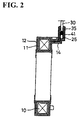
- FIGS. 1 to 11 In this embodiment is illustrated a coil device constructing a solenoid device.
- the coil device has a covering element 12 which is formed e.g. of a synthetic resin around a bobbin or coil form 11, in which a coil 10 is mounted, e.g. by molding, and substantially has an annular shape as a whole.
- a connecting portion 14 is integrally or unitarily formed with the covering element 12 such that it preferably projects from a part of one outer side surface of the covering element 12, and lead wires 30 are connected with connection terminals 25 projecting from the connecting portion 14.
- the connecting portion 14 projects from the covering element 12 as described above.
- the connecting portion 14 has a base portion 15 which bulges out so as to be substantially in flush with the radially outer surface of the covering element 12 and to have specified thickness and width as shown in FIGS. 3 to 5.
- a recess 15A is formed in the upper or lateral or radially outward surface of the base portion 15.
- a receiving portion 16 which is rectangular in plan view, bulges out from the outer surface of the base portion 15.
- the upper surface of the receiving portion 16 is located below or radially inward from that of the base portion 15.
- the receiving portion 16 is thick at its inner side (thick portion 16A) so that its bottom surface substantially is in alignment with the bottom surface of the base portion 15 while being thin at its outer side (thin portion 16B) by having its bottom surface raised or stepped.
- the bottom surface of the thick portion 16A obliquely extends at its opposite ends as shown in FIG. 4. These oblique surfaces serve as a pair of first locking surfaces 18, and the bottom surface of the thin portion 16B serves as a second locking surface 19.
- an insertion slot 21 having a specified depth is made or formed in the upper surface of the connecting portion 14 between the base portion 15 and the receiving portion 16.
- an engaging projection 23 which is slightly smaller than the receiving portion 16 in cross section.
- This engaging projection 23 preferably is in the form substantially of a rectangle having round corners, and the upper surface thereof slightly protrudes from that of the base portion 15.
- the engaging projection 23 is formed with a pair of mount holes 24 which are spaced apart by a specified distance, and connection terminals 25 project from the mount holes 24.
- connection terminals 25 are formed e.g. by pressing or folding an electrically conductive metal plate.
- Each connection terminal 25 has a substantially round tubular portion 26, as shown in FIG. 3, into which a core 31 of the lead wire 30 is at least partly insertable, and a substantially vertically extending seam 27 is formed in an outer surface (right side in FIG. 3) thereof. Further, a groove 28 dividing the round tubular portion 26 into first or upper and second or lower sections is made in the outer surface of the round tubular portion 26 substantially at a center position with respect to height direction in such a manner as to extend substantially over half the circumference.
- connection terminals 25 are embedded in the mount holes 24, and L-shaped legs 29 projecting from the bottom ends of the inner surfaces of the round tubular portions 26 are inserted or insertable into the bobbin 11, the leading ends of the legs 29 being connected or connectable with the opposite ends of a wire forming the coil 10.
- the two connection terminals 25 are secured to the bobbin 11 preferably in advance as inserts when the covering element 12 is molded, and are so arranged as project from positions slightly below the dividing grooves 28 as the covering element 12 and the connecting portion 14 are formed.
- a rubber or sealing plug 35 is mounted on the engaging projection 23 of the connecting portion 14.
- This rubber plug 35 is substantially in the form of a rectangular tube having a thick upper wall 36 as also shown in FIG. 6, and lips 37 are formed on the inner surface of its bottom end portion, so that the rubber plug 35 can be substantially closely fitted to the outer surface of the engaging projection 23.
- On the upper surface of the upper wall 36 are formed two boss portions 38 preferably having the substantially same spacing as the connection terminals 25, and an insertion hole 39 for the lead wire 30 is so formed in the center of each boss portion 38 as to extend to the bottom surface of the upper wall 36. Lips 40 are formed on the inner surface of each insertion hole 39.
- a cover 41 for substantially covering the outer surface of the rubber plug 35 is also provided.
- This cover 41 is formed e.g. by pressing or folding a metal plate having a high rigidity. More specifically, as shown in FIG. 7, the cover 41 is substantially in the form of a rectangular tube capable of substantially covering the rubber plug 35 over its entire height.
- a pair of first crimping or bending pieces 42 project from the opposite shorter sides of the bottom end of the cover 41, and a second crimping or bending piece 43 projects from one of the longer sides. Further, the bottom end of the other longer side serves as an insertion end 44 at least partly insertable into the insertion slot 21 of the connecting portion 14.
- a pair of pressing pieces 45 are formed in the substantially middle of the longer sides of the upper end of the cover 41 with respect to widthwise direction by being bent inward at an angle different from 0° or 180°, preferably substantially at right angles in advance.
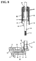
- the rubber plug 35 is accommodated in the cover 41 as shown in FIG. 8, and the two lead wires 30 are inserted into the corresponding insertion holes 39 of the rubber plug 35 from above. Then, the leading ends of the lead wires 30 are stripped to expose the cores 31.
- the cores 31 of the lead wires 30 are inserted into the upper or first ends of the round tubular portions 26 of the connection terminals 25, and the connection terminals 25 are secured to the cores 31 preferably by crimping the upper ends of the round tubular portions 26 as shown in FIG. 9.
- the round tubular portions 26 are divided into the upper and lower sections by the grooves 28, it prevents a crimping force from being transmitted to the lower ends of the round tubular portions 26, thereby preventing the engaging projection 23 from being cracked.
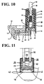
- the cover 41 accommodating the rubber plug 35 is pushed down or along an insertion direction along the lead wires 30 while being oriented such that the insertion end 44 is located e.g. at the left side of FIG. 9 or at the side of the insertion slot 21, until the insertion end 44 reaches the bottom of the insertion slot 21 as shown in FIG. 10.
- the bottom end of the rubber plug 35 accommodated in the cover 41 is substantially fitted on the engaging projection 23.
- the second crimping piece 43 hangs down or positioned outside the second locking surface 19 as indicated by solid line in FIG. 10, and the pair of first crimping pieces 42 hang down outside the first locking surfaces 18 as indicated by chain line in FIG. 11.
- the cover 41 is secured to the connecting portion 14 so as not to disengage therefrom.
- the inner surface of the bottom end portion of the rubber plug 35 is substantially closely adhered to the outer surface of the engaging projection 23 while the lips 37 are being deformed.
- the inner surfaces of the two insertion holes 39 of the rubber plug 35 are substantially closely adhered to the outer surfaces of the lead wires 30 while the lips 40 are being deformed. In this way, a portion connecting the lead wires 30 and the connection terminals 25, i.e. the lead wire drawing portion is sealed.
- the rubber plug 35 is used as a sealing member according to this embodiment, it is satisfactorily adhered not only to the outer surfaces of the lead wires 30, but also to the engaging projections 23 made e.g. of a relatively hard resin, thereby providing a high sealability. Further, since the rubber plug 35 is covered by the cover 41 having a high rigidity, the rubber plug 35 is stably held even if, for example, the lead wires 30 are shaken, and the large lips can be provided even if the wall of the rubber plug 35 is thin, with the result that the rubber plug 35 is allowed to have a small size. Furthermore, since the cover 41 is mounted by at least partly inserting the insertion end 44 into the insertion slot 21, it can be excellently held.
- each connection terminal 25 projecting from the engaging projection 23 to be connected with the lead wire 30 is substantially round tubular and remains within the surface area of the engaging projection 23.
- a portion of the connection terminal 25 to be crimped with the lead wire 30 is in the form of an open barrel and bulges out of the outer periphery of the engaging projection 23, it is difficult to take the connecting portion 14 out of a mold if the connecting porion 14 is molded using the connection terminals 25 as inserts.
- the portion of the connection terminal 25 to be crimped is formed into the round tubular portion 26 and remains within the surface area of the engaging projection 23. Accordingly, the connecting portion 14 can be taken out of the mold without bringing a parting line to the outer circumferential surface of the engaging projection 23. Thus, the outer circumferential surface of the engaging projection can be securely made smooth, ensuring an excellent sealability of the rubber plug 35.
- connection terminal 25 is round tubular, such a construction of the mold as to prevent resin from leaking into the connection terminal 25 can be simplified.
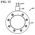
- FIGS. 12 to 19 In this embodiment is illustrated a coil device 110 constructing a solenoid device.
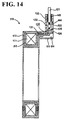
- the coil device 110 has a following construction. As shown in FIGS. 12 to 14, a covering element 113 made e.g. of a synthetic resin is formed around a bobbin or coil form 112, in which a coil 111 is mounted, by molding and the coil device 110 substantially has an annular shape as a whole.
- a connecting portion 115 is integrally or unitarily formed with a portion of the outer surface of the covering element 113 and projects therefrom, and one end of each lead wire 121 is connected or connectable with a corresponding connection terminal 130 projecting from or on the connecting portion 115.
- the other end of each lead wire 121 is secured to a female terminal fitting 117 and mounted in a watertight connector 118 as shown in FIG. 13.
- This watertight connector 118 is preferably mounted on an unillustrated fixing member e.g. by a clip 119.
- the connecting portion 115 projects from the covering element 113 as described above. As shown in FIGS. 15 and 16, the connecting portion 115 projects from the covering element 113 in such a manner that the outer surface thereof is substantially in flush with that of the covering element 113 and it has specified thickness and width. A recess 124 is formed in the projecting surface of the connecting portion 115.
- An engaging projection 125 which preferably is substantially rectangular in plan view is formed on the upper surface of the leading end of the connecting portion 115.
- an insertion recess 126 which is substantially continuous with the leading end surface of the engaging projection 125.
- An insertion slot 127 having a specified depth is formed in the middle of the upper surface of the engaging projection 125 with respect to widthwise direction as shown in FIG. 15. Further, a pair of locking projections 128 are formed on the left and right side surfaces of the connecting portion 115.
- connection terminals 130 project from the upper or lateral surface of the engaging projection 125 of the connecting portion 115.
- Each connection terminal 130 is formed e.g. by pressing or bending an electrically conductive metal plate such that a tubular barrel 132 (substantially closed barrel) into which a core 122 of the lead wire 121 is fittable is formed at the rear end of a substantially L-shaped or bent leg portion 131.
- connection terminals 130 are fixed by being pressed into the bobbin 112 and/or by insert-molding, and connected with the opposite ends of a strand forming the coil 111 by soldering or crimping.
- the barrels 132 are so arranged as to project upward or in a connection direction from the engaging projection 125 as the covering element 113 and the connecting portion 115 are formed.
- a cover 135 is mounted on the engaging projection 125 of the connecting portion 115.
- This cover 135 is formed e.g. of a synthetic resin to have an outer configuration of a substantially rectangular tube, and its bottom end portion is fittable on the engaging projection 125.
- the outer part (right side of FIG. 16) and left and right parts are substantially longer than the inner part so that the outer part reaches the bottom of the insertion recess 126 when the inner part comes into contact with the upper surface of the connecting portion 115.
- elastic locking pieces 136 each formed with a projection 137 engageable with the corresponding locking protection 128 hang down from the inner sides of the left and right parts.
- a horizontal or inwardly projecting wall 139 is formed in a position toward its upper end in the cover 135, and a rubber or sealing plug accommodating recess 140 is defined above the horizontal wall 139.
- a vertical or longitudinally extending wall 141 having a specified length hangs down from the substantially middle of the lower surface of the horizontal wall 139 with respect to its widthwise direction, and barrel accommodating portions 143 for individually accommodating barrels 132 of the connection terminals 130 are defined at the opposite sides of the vertical wall 141.
- two insertion holes 142 through which the lead wires 121 are inserted are formed in the horizontal wall 139 at the opposite sides of the vertical wall 141.
- the bottom end of the vertical wall 141 is fittable into an insertion groove or slot or recess 127 formed in the upper surface of the engaging projection 125. Further, a window 144 in communication with the both barrel accommodating portions 143 are preferably formed in the front surface of the cover 135.
- a rubber or sealing plug 145 is at least partly fittable into the rubber plug accommodating recess 140 of the cover 135.
- This rubber plug 145 is fittable into the accommodating recess 140 in a watertight manner by the presence of lips 146 formed on its outer circumferential surface, and two insertion holes 147 through which the lead wires 121 are insertable are formed therein.
- Lips 148 are formed on the inner surfaces of the insertion holes 147.
- the rubber plug 145 is accommodated in the rubber plug accommodating recess 140 of the cover 135 as shown in FIG. 17, and the two lead wires 121 are inserted into the corresponding insertion holes 147 of the rubber plug 145 from above and drawn down the cover 135 through the insertion holes 142.
- the leading ends of the lead wires 121 are stripped to expose the core 122.
- the cores 122 of the lead wires 121 are then inserted into the barrels 132 of the connection terminals 132, which barrels are crimped or soldered to be fastened to the cores 122 as shown in FIG. 18.
- the cover 135 accommodating the rubber plug 145 is lowered along the lead wires 121 until the inner part of the bottom end thereof comes into contact with the upper surface of the connecting portion 115 as shown in FIG. 19. At this time, the outer part of the bottom end of the cover 135 is pushed down to the bottom of the insertion recess 126. Further, as shown in FIG.
- the bottom end of the vertical wall 141 in the cover 135 is fitted into the insertion groove 127 of the engaging projection 125; the crimped or soldered barrels 132 of the respective connection terminals 130 are accommodated in the barrel accommodating portions 143 at the opposite sides of the vertical wall 143; and the projections 137 of the elastic locking pieces 136 are elastically engaged with the locking projections 128 below the locking projections 128. In this way, the cover 135 is lockingly mounted.
- the cover 135 functions as a means for preventing the lead wires 121 from shaking, thereby strengthening the lead wire drawing construction. Further, the rubber plug 145 functions as a cushion when the lead wires 121 are shaken.
- sealing material such as an epoxy resin is filled into the barrel accommodating portions 143 through the window 144 formed in the cover 135, sealing can be provided for the lead wire drawing portion as well as for the rubber plug 145.
- connection terminals 130 are provided in the connecting portion 115 while the barrels 132 thereof are projecting therefrom. Accordingly, the lead wires 121 and the connection terminals 130 can be connected only by crimping or soldering the barrels 132 to fasten them to the cores 122 of the lead wires 121. This eliminates the need for providing intermediate terminals or the like for the connection of the lead wires 121, thereby reducing the number of parts and the number of operation steps. As a result, production costs can be reduced.
- the lead wires 121 can be connected with the connection terminals 130 even with the connectors 118 mounted in advance, making the assembling operation more flexible.
- sealing material is filled into the cover 135, sealing can be easily and securely provided for the lead wire drawing portion, with the result that the coil device 110 can easily cope with the use in oil or water.
Landscapes
- Engineering & Computer Science (AREA)
- Power Engineering (AREA)
- Electromagnets (AREA)
Applications Claiming Priority (4)
| Application Number | Priority Date | Filing Date | Title |
|---|---|---|---|
| JP9777499 | 1999-04-05 | ||
| JP09777499A JP4066555B2 (ja) | 1999-04-05 | 1999-04-05 | コイル装置 |
| JP11319499A JP4019553B2 (ja) | 1999-04-21 | 1999-04-21 | コイル装置 |
| JP11319499 | 1999-04-21 |
Publications (1)
| Publication Number | Publication Date |
|---|---|
| EP1043735A1 true EP1043735A1 (de) | 2000-10-11 |
Family
ID=26438922
Family Applications (1)
| Application Number | Title | Priority Date | Filing Date |
|---|---|---|---|
| EP00107075A Withdrawn EP1043735A1 (de) | 1999-04-05 | 2000-04-05 | Spulenanordnung und Verfahren zum Verbinden einer solchen Spulenanordnung |
Country Status (1)
| Country | Link |
|---|---|
| EP (1) | EP1043735A1 (de) |
Cited By (5)
| Publication number | Priority date | Publication date | Assignee | Title |
|---|---|---|---|---|
| US8106737B2 (en) | 2009-03-31 | 2012-01-31 | Denso Corporation | Terminal structure of coil device |
| EP2654046A3 (de) * | 2012-04-18 | 2016-11-23 | Hamilton Sundstrand Corporation | Abgedichtete Spulenverbindung mit Litzdraht |
| EP2660831A3 (de) * | 2012-04-30 | 2017-06-14 | Honeywell International Inc. | Hochtemperatur-Elektromagnetspulenanordnungen mit geflochtenen Leitdrähten und Verfahren zu deren Herstellung |
| EP2660832A3 (de) * | 2012-04-30 | 2017-06-14 | Honeywell International Inc. | Hochtemperatur-Elektromagnetspulenanordnungen mit hartgelöteten geflochtenen Leitdrähten und Verfahren zu deren Herstellung |
| CN107046184A (zh) * | 2015-12-16 | 2017-08-15 | 矢崎总业株式会社 | 压接端子 |
Citations (5)
| Publication number | Priority date | Publication date | Assignee | Title |
|---|---|---|---|---|
| US3422392A (en) * | 1966-06-08 | 1969-01-14 | Westinghouse Electric Corp | Electrical bushing assembly |
| US3932828A (en) * | 1973-10-23 | 1976-01-13 | Coils, Inc. | Encapsulated coil and method of making the same |
| WO1993007654A1 (en) * | 1991-10-11 | 1993-04-15 | Raychem Corporation | Telecommunications terminal block |
| FR2693319A1 (fr) * | 1992-07-02 | 1994-01-07 | Sit La Precisa Srl | Connecteur à câble électrique, en particulier pour l'alimentation de bobines d'électroaimants. |
| WO1996020516A1 (en) * | 1994-12-23 | 1996-07-04 | Raychem Corporation | Coaxial cable connector |
-
2000
- 2000-04-05 EP EP00107075A patent/EP1043735A1/de not_active Withdrawn
Patent Citations (5)
| Publication number | Priority date | Publication date | Assignee | Title |
|---|---|---|---|---|
| US3422392A (en) * | 1966-06-08 | 1969-01-14 | Westinghouse Electric Corp | Electrical bushing assembly |
| US3932828A (en) * | 1973-10-23 | 1976-01-13 | Coils, Inc. | Encapsulated coil and method of making the same |
| WO1993007654A1 (en) * | 1991-10-11 | 1993-04-15 | Raychem Corporation | Telecommunications terminal block |
| FR2693319A1 (fr) * | 1992-07-02 | 1994-01-07 | Sit La Precisa Srl | Connecteur à câble électrique, en particulier pour l'alimentation de bobines d'électroaimants. |
| WO1996020516A1 (en) * | 1994-12-23 | 1996-07-04 | Raychem Corporation | Coaxial cable connector |
Cited By (6)
| Publication number | Priority date | Publication date | Assignee | Title |
|---|---|---|---|---|
| US8106737B2 (en) | 2009-03-31 | 2012-01-31 | Denso Corporation | Terminal structure of coil device |
| EP2654046A3 (de) * | 2012-04-18 | 2016-11-23 | Hamilton Sundstrand Corporation | Abgedichtete Spulenverbindung mit Litzdraht |
| EP2660831A3 (de) * | 2012-04-30 | 2017-06-14 | Honeywell International Inc. | Hochtemperatur-Elektromagnetspulenanordnungen mit geflochtenen Leitdrähten und Verfahren zu deren Herstellung |
| EP2660832A3 (de) * | 2012-04-30 | 2017-06-14 | Honeywell International Inc. | Hochtemperatur-Elektromagnetspulenanordnungen mit hartgelöteten geflochtenen Leitdrähten und Verfahren zu deren Herstellung |
| CN107046184A (zh) * | 2015-12-16 | 2017-08-15 | 矢崎总业株式会社 | 压接端子 |
| CN107046184B (zh) * | 2015-12-16 | 2019-08-02 | 矢崎总业株式会社 | 压接端子 |
Similar Documents
| Publication | Publication Date | Title |
|---|---|---|
| JP3023276U (ja) | 電気コネクタ | |
| EP1583183B1 (de) | Wasserdichter Verbinder und sein Zusammenbauverfahren | |
| JP2863083B2 (ja) | コネクタ用防水栓 | |
| JP3691291B2 (ja) | 防水コネクタ | |
| US6790087B2 (en) | Electrical connector having a wire guide | |
| US20020190850A1 (en) | Ultrasonic obstacle detector and method of assembling the same | |
| US6059594A (en) | Sealed electrical connector | |
| US9093759B2 (en) | Connection structure for electric wire and terminal | |
| US20040002260A1 (en) | Insert-molded connector and method of forming it | |
| EP0942494B1 (de) | Wasserdichter Verbinder und dessen Zusammenbau | |
| US8087945B2 (en) | Electric connector with a dust cover | |
| EP0738025B1 (de) | Abgedichtete elektrische Verbinderanordnung | |
| JP2712880B2 (ja) | 電線インサートコネクタの成形方法 | |
| JP2586314Y2 (ja) | 防水コネクタ | |
| EP1043735A1 (de) | Spulenanordnung und Verfahren zum Verbinden einer solchen Spulenanordnung | |
| US6129589A (en) | Terminal retention system | |
| JP2003045550A (ja) | 防水コネクタ | |
| JP3119119B2 (ja) | 圧接ジョイントコネクタ | |
| JPH09320698A (ja) | 同軸コネクター | |
| KR101651653B1 (ko) | 와이어 투 와이어 커넥터 조립체 | |
| JP4019553B2 (ja) | コイル装置 | |
| JP4066555B2 (ja) | コイル装置 | |
| JPS63207062A (ja) | 電話ケ−ブル用のコネクタ | |
| JP2002289292A (ja) | 防水コネクタ | |
| CN210008045U (zh) | 控制器壳体及整车控制器 |
Legal Events
| Date | Code | Title | Description |
|---|---|---|---|
| PUAI | Public reference made under article 153(3) epc to a published international application that has entered the european phase |
Free format text: ORIGINAL CODE: 0009012 |
|
| 17P | Request for examination filed |
Effective date: 20000427 |
|
| AK | Designated contracting states |
Kind code of ref document: A1 Designated state(s): DE FR GB IT |
|
| AX | Request for extension of the european patent |
Free format text: AL;LT;LV;MK;RO;SI |
|
| AKX | Designation fees paid |
Free format text: DE FR GB IT |
|
| 17Q | First examination report despatched |
Effective date: 20030903 |
|
| STAA | Information on the status of an ep patent application or granted ep patent |
Free format text: STATUS: THE APPLICATION IS DEEMED TO BE WITHDRAWN |
|
| 18D | Application deemed to be withdrawn |
Effective date: 20040114 |