EP1043195A2 - Faltverfahren für den Luftsack eines Seitenairbags - Google Patents
Faltverfahren für den Luftsack eines Seitenairbags Download PDFInfo
- Publication number
- EP1043195A2 EP1043195A2 EP00107079A EP00107079A EP1043195A2 EP 1043195 A2 EP1043195 A2 EP 1043195A2 EP 00107079 A EP00107079 A EP 00107079A EP 00107079 A EP00107079 A EP 00107079A EP 1043195 A2 EP1043195 A2 EP 1043195A2
- Authority
- EP
- European Patent Office
- Prior art keywords
- folding
- edge
- folded
- airbag
- parallel
- Prior art date
- Legal status (The legal status is an assumption and is not a legal conclusion. Google has not performed a legal analysis and makes no representation as to the accuracy of the status listed.)
- Granted
Links
Images



Classifications
-
- B—PERFORMING OPERATIONS; TRANSPORTING
- B60—VEHICLES IN GENERAL
- B60R—VEHICLES, VEHICLE FITTINGS, OR VEHICLE PARTS, NOT OTHERWISE PROVIDED FOR
- B60R21/00—Arrangements or fittings on vehicles for protecting or preventing injuries to occupants or pedestrians in case of accidents or other traffic risks
- B60R21/02—Occupant safety arrangements or fittings, e.g. crash pads
- B60R21/16—Inflatable occupant restraints or confinements designed to inflate upon impact or impending impact, e.g. air bags
- B60R21/23—Inflatable members
- B60R21/237—Inflatable members characterised by the way they are folded
-
- B—PERFORMING OPERATIONS; TRANSPORTING
- B60—VEHICLES IN GENERAL
- B60R—VEHICLES, VEHICLE FITTINGS, OR VEHICLE PARTS, NOT OTHERWISE PROVIDED FOR
- B60R21/00—Arrangements or fittings on vehicles for protecting or preventing injuries to occupants or pedestrians in case of accidents or other traffic risks
- B60R21/02—Occupant safety arrangements or fittings, e.g. crash pads
- B60R21/16—Inflatable occupant restraints or confinements designed to inflate upon impact or impending impact, e.g. air bags
- B60R21/23—Inflatable members
- B60R21/237—Inflatable members characterised by the way they are folded
- B60R2021/2375—Folding devices
-
- B—PERFORMING OPERATIONS; TRANSPORTING
- B60—VEHICLES IN GENERAL
- B60R—VEHICLES, VEHICLE FITTINGS, OR VEHICLE PARTS, NOT OTHERWISE PROVIDED FOR
- B60R21/00—Arrangements or fittings on vehicles for protecting or preventing injuries to occupants or pedestrians in case of accidents or other traffic risks
- B60R21/02—Occupant safety arrangements or fittings, e.g. crash pads
- B60R21/16—Inflatable occupant restraints or confinements designed to inflate upon impact or impending impact, e.g. air bags
- B60R21/23—Inflatable members
- B60R21/231—Inflatable members characterised by their shape, construction or spatial configuration
- B60R21/23138—Inflatable members characterised by their shape, construction or spatial configuration specially adapted for side protection
-
- Y—GENERAL TAGGING OF NEW TECHNOLOGICAL DEVELOPMENTS; GENERAL TAGGING OF CROSS-SECTIONAL TECHNOLOGIES SPANNING OVER SEVERAL SECTIONS OF THE IPC; TECHNICAL SUBJECTS COVERED BY FORMER USPC CROSS-REFERENCE ART COLLECTIONS [XRACs] AND DIGESTS
- Y10—TECHNICAL SUBJECTS COVERED BY FORMER USPC
- Y10S—TECHNICAL SUBJECTS COVERED BY FORMER USPC CROSS-REFERENCE ART COLLECTIONS [XRACs] AND DIGESTS
- Y10S493/00—Manufacturing container or tube from paper; or other manufacturing from a sheet or web
- Y10S493/94—Bellows
Definitions
- the invention relates to a method for folding an airbag of a side airbag into a Pack form, which consists of a substantially rectangular, rounded corners at the corners exists, which is folded along a folding edge A into an approximately square shape is and its superimposed, free edges to form a closed Air bags are connected to each other and in the area of the folding edge A a connection plate for a gas generator with fastening bolts projecting outwards through the fabric can be arranged.
- the packaging form of an airbag for an airbag module is determined once by the one available Installation space and the desired expansion behavior of the airbag when explosive inflation in an accident situation.
- side airbags the the risk of injury to the vehicle occupants when directed transversely to the vehicle's longitudinal axis
- the designer must reduce the acceleration forces proportionately small installation spaces and secondly very short inflation times realize that are in the range of 20 to 30% of the inflation times for front airbags be available. Packing forms that meet these conditions must also be as economically feasible as possible.
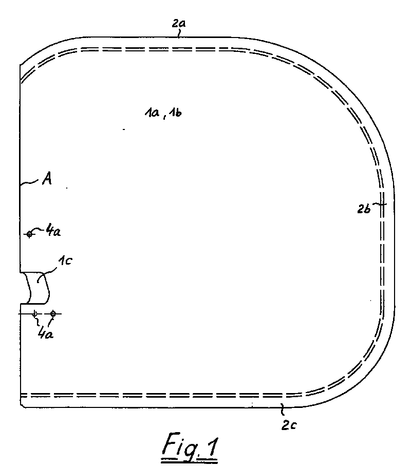
- FIG. 1 shows a fabric section 1 with layers one on top of the other Fabric section halves 1a and 1b, which have a common folded edge A and have interconnected edges 2a, 2b, 2c.
- a connecting plate 3 see Fig. 3
- the fastening bolts 4 protrude through the holes 4a to the outside.
- the upper edge 2a is between the tissue section halves 1a and 1b turned over so that it essentially the lower edge 2c is parallel.
- the right part of the packaging form 5 becomes approximately along the folding line D. 90 ° from the plane parallel to the connecting plate 3 folded down, between two layers each of the tissue section halves 1a, 1b a space 7 for inserting one Folding rulers is formed.
- the flip down is done using a Folding ruler 6, which is applied parallel to the folding edge A.
- Based on the folded shape according to Figure 4 are then inserted using inserted and outside Folding rulers 8, 9, 10 made the folds resulting from FIGS. 5 to 7, whereby the largest part of the airbag is placed on top of one another in a meandering shape.
- the thickness of the tissue section halves 1a, 1b is enlarged compared to the longitudinal and transverse dimensions of the airbag, otherwise the individual layers of the tissue section are not visible in the drawing could be made. As a result, the thickness of the folding package appears much larger than in reality.
- the folding method according to the invention differs from previously known in the first Line in that about half of the original shape is turned into the other half is and that the reduction of the areal extension essentially by meandering Folding is achieved.
- shooting attempts it was found that the with the method according to the invention, the pack shape achieved when the Propellant deployed easily and that the airbag easily within the range of 10 milliseconds inflation time reaches its final shape and thus the optimal Can perform a protective function.
- the folding method according to the invention is not essential limited to the starting form shown in the exemplary embodiment. It is decisive only that a doubling of the fabric layers can be achieved by inlaying and that is then folded in a meandering shape.
Landscapes
- Engineering & Computer Science (AREA)
- Mechanical Engineering (AREA)
- Air Bags (AREA)
- Folding Of Thin Sheet-Like Materials, Special Discharging Devices, And Others (AREA)
Abstract
- der zur Faltkante A etwa senkrecht verlaufende Rand (2a) des das Anschlußblech (3) nicht enthaltenden Teils des Luftsacks wird in den Luftsack eingestülpt (Faltkante C), so daß er parallel und benachbart zum gegenüberliegenden Rand (2c) liegt und daß eine im wesentlichen überall vierlagige, sich parallel zum Anschlußblech (3) erstreckende Faltform entsteht,
- die beiden Gewebeabschnittshälften (1a, 1b) werden parallel zur Faltkante A zu einer Faltform (5) eingefaltet, bei der das Anschlußblech (3) unmittelbar neben einer randseitigen Faltkante B1 liegt, die dieser Faltkante gegenüberliegenden Ränder (2b) der Gewebeabschnitte (1a, 1b) nebeneinanderliegend angeordnet sind und das Anschlußblech (3) und die Gewebeabschnitte (1a, 1b) in zueinander parallelen Ebenen liegen,
- diese Faltform (5) wird unter Verwendung eines Faltlineals (6) längs zur Faltkante A sowie zueinander paralleler und vom Anschlußblech (3) sowie voneinander beabstandeter Faltkanten (D) um etwa 90° aus der zum Anschlußblech (3) parallelen Ebene nach unten umgelegt, wobei zwischen je zwei Lagen der Gewebeabschnitte (1a, 1b) ein Freiraum (7) für das Einschieben eines Faltlineals gebildet wird,
- der Freiraum (7) wird mittels eines Faltlineals (8) verbreitert, und das restliche Gewebematerial wird anschließend mittels weiterer, außen angreifender und eingeschobener Faltlineale (9, 10) beidseitig von der Mitte des Freiraums (7) mehrfach mäanderförmig in zum Anschlußblech (3) parallele Lagen eingefaltet (Faltkanten E) und es wird schließlich
- die so entstandene Packform (11) um zwei senkrecht zueinander verlaufende Faltkante (F und G) um 180° umgelegt und rückseitig an den das Anschlußblech (3) enthaltenden Luftsackbereich angedrückt.
Description
- der zur Faltkante A etwa senkrecht verlaufende Rand des das Anschlußblech (3) nicht enthaltenden Teils des Luftsacks wird in den Luftsack eingestülpt, so daß er parallel und benachbart zum gegenüberliegenden Rand liegt und daß eine im wesentlichen überall vierlagige, sich parallel zum Anschlußblech erstreckende Faltform entsteht,
- die beiden Gewebeabschnittshälften werden parallel zur Faltkante A zu einer Faltform eingefaltet, bei der das Anschlußblech unmittelbar neben einer randseitigen Faltkante liegt, die dieser Faltkante gegenüberliegenden Ränder der Gewebeabschnitte nebeneinanderliegend angeordnet sind und das Anschlußblech und die Gewebeabschnitte in zueinander parallelen Ebenen liegen,
- diese Faltform wird unter Verwendung eines Faltlineals längs zur Faltkante sowie zueinander paralleler und vom Anschlußblech sowie voneinander beabstandeter Faltkanten um etwa 90° aus der zum Anschlußblech parallelen Ebene nach unten umgelegt, wobei zwischen je zwei Lagen der Gewebeabschnitte ein Freiraum für das Einschieben eines Faltlineals gebildet wird,
- der Freiraum wird mittels eines Faltlineals verbreitert, und das restliche Gewebematerial wird anschließend mittels weiterer, außen angreifender und eingeschobener Faltlineale beidseitig von der Mitte des Freiraums mehrfach mäanderförmig in zum Anschlußblech parallele Lagen eingefaltet, und es wird schließlich
- die so entstandene Packform um zwei senkrecht zueinander verlaufende Faltkante um 180° umgelegt und rückseitig an den das Anschlußblech enthaltenden Luftsackbereich angedrückt.
Das erfindungsgemäße Faltverfahren wird anhand des in den Figuren 1 bis 9 dargestellten Ausführungsbeispiels näher erläutert. Es zeigen:
- Figur 1
- die Ausgangsform des Luftsacks;
- Figur 2
- in einer Draufsicht und einer Schnittansicht einen ersten Faltschritt, durch den die eine Hälfte des Luftsacks in die andere eingestülpt wird;
- Figur 3
- in einer Draufsicht und einer Schnittansicht einen zweiten Faltschritt zur Anordnung des Anschlußbleches in der Erstreckungsebene des Luftsacks;
- Figur 4
- in einer Draufsicht und einer Schnittansicht den nächsten Faltschritt, durch den der Bereich neben dem Anschlußblech um etwa 90° geklappt wird;
- Figur 5 bis 7
- in einer Schnittansicht weitere Faltschritte;
- Figur 8
- in einer Draufsicht und einer Schnittansicht die mit dem vorletzten Faltschritt erreichte Packform;
- Figur 9
- in einer Draufsicht und einer Schnittansicht die endgültige Packform.
Claims (3)
- Verfahren zum Falten eines Luftsacks eines Seitenairbags in einer Packform, der aus einem im wesentlichen rechteckigen, an den Ecken gerundeten Gewebeabschnitt (1) besteht, der längs einer Faltkante A auf eine etwa quadratische Form gefaltet ist und dessen übereinandergelegte, freie Ränder (2a, 2b, 2c) zur Ausbildung eines geschlossenen Luftsacks miteinander verbunden sind und in dem im Bereich der Faltkante A ein Anschlußblech (3) für einen Gasgenerator mit nach außen durch das Gewebe vorstehenden Befestigungsbolzen (4) angeordnet werden kann, gekennzeichnet durch folgende Schritte:der zur Faltkante A etwa senkrecht verlaufende Rand (2a) des das Anschlußblech (3) nicht enthaltenden Teils des Luftsacks wird in den Luftsack eingestülpt (Faltkante C), so daß er parallel und benachbart zum gegenüberliegenden Rand (2c) liegt und daß eine im wesentlichen überall vierlagige, sich parallel zum Anschlußblech (3) erstreckende Faltform entsteht,die beiden Gewebeabschnittshälften (1a, 1b) werden parallel zur Faltkante A zu einer Faltform (5) eingefaltet, bei der das Anschlußblech (3) unmittelbar neben einer randseitigen Faltkante B1 liegt, wobei die dieser Faltkante gegenüberliegenden Ränder (2b) der Gewebeabschnitte (1a, 1b) nebeneinanderliegend angeordnet sind und das Anschlußblech (3) und die Gewebeabschnitte (1a, 1b) in zueinander parallelen Ebenen liegen,diese Faltform (5) wird unter Verwendung eines Faltlineals (6) längs zur Faltkante A sowie zueinander paralleler und vom Anschlußblech (3) sowie voneinander beabstandeter Faltkanten (D) um etwa 90° aus der zum Anschlußblech (3) parallelen Ebene nach unten umgelegt, wobei zwischen je zwei Lagen der Gewebeabschnitte (1a, 1b) ein Freiraum (7) für das Einschieben eines Faltlineals gebildet wird,der Freiraum (7) wird mittels eines Faltlineals (8) verbreitert, und das restliche Gewebematerial wird anschließend mittels weiterer, außen angreifender und eingeschobener Faltlineale (9, 10) beidseitig von der Mitte des Freiraums (7) mehrfach mäanderförmig in zum Anschlußblech (3) parallele Lagen eingefaltet (Faltkanten E) und es wird schließlichdie so entstandene Packform (11) um zwei senkrecht zueinander verlaufende Faltkante (F und G) um 180° umgelegt und rückseitig an den das Anschlußblech (3) enthaltenden Luftsackbereich angedrückt.
- Verfahren nach Anspruch 1, dadurch gekennzeichnet, daß von einem Luftsack ausgegangen wird, in dem das Anschlußblech (3) symmetrisch zur Faltkante A angeordnet ist.
- Verfahren nach Anspruch 1, dadurch gekennzeichnet, daß von einem Luftsack ausgegangen wird, in dem das Anschlußblech (3) asymmetrisch zur Faltkante A angeordnet ist.
Applications Claiming Priority (2)
| Application Number | Priority Date | Filing Date | Title |
|---|---|---|---|
| DE19916084 | 1999-04-09 | ||
| DE19916084A DE19916084A1 (de) | 1999-04-09 | 1999-04-09 | Faltverfahren für den Luftsack eines Seitenairbags |
Publications (4)
| Publication Number | Publication Date |
|---|---|
| EP1043195A2 true EP1043195A2 (de) | 2000-10-11 |
| EP1043195A3 EP1043195A3 (de) | 2001-11-07 |
| EP1043195A9 EP1043195A9 (de) | 2002-02-27 |
| EP1043195B1 EP1043195B1 (de) | 2003-07-23 |
Family
ID=7904043
Family Applications (1)
| Application Number | Title | Priority Date | Filing Date |
|---|---|---|---|
| EP00107079A Expired - Lifetime EP1043195B1 (de) | 1999-04-09 | 2000-04-05 | Faltverfahren für den Luftsack eines Seitenairbags |
Country Status (5)
| Country | Link |
|---|---|
| US (1) | US6432033B1 (de) |
| EP (1) | EP1043195B1 (de) |
| JP (1) | JP2000301999A (de) |
| DE (2) | DE19916084A1 (de) |
| ES (1) | ES2201962T3 (de) |
Families Citing this family (17)
| Publication number | Priority date | Publication date | Assignee | Title |
|---|---|---|---|---|
| DE10130473B4 (de) * | 2001-06-25 | 2017-08-03 | Autoliv Development Ab | Faltverfahren |
| DE10163447B4 (de) * | 2001-12-21 | 2004-12-09 | Breed Automotive Technology, Inc., Lakeland | Verfahren und Vorrichtung zum Falten eines Gassacks eines Airbags-Moduls |
| DE20301431U1 (de) | 2003-01-23 | 2003-04-24 | Takata Petri Gmbh Ulm | Gassack für eine Insassenschutzeinrichtung |
| US20050090336A1 (en) * | 2003-09-09 | 2005-04-28 | Nye S. C. | Poolside goal system |
| ES2278487B1 (es) * | 2005-02-04 | 2008-06-16 | Giro Gh, S.A. | Dispositivo de pliegue. |
| US7845682B2 (en) * | 2005-04-27 | 2010-12-07 | Autoliv Asp, Inc. | Airbag cushion folding methods |
| US7441804B2 (en) * | 2005-04-27 | 2008-10-28 | Autoliv Asp, Inc. | Airbag cushion folding method |
| US7942442B2 (en) * | 2005-04-27 | 2011-05-17 | Autoliv Asp, Inc. | Airbag cushion folding methods |
| US7926844B2 (en) | 2008-04-10 | 2011-04-19 | Autoliv Asp, Inc. | Airbag assembly and method of packing |
| US20100323868A1 (en) * | 2009-06-18 | 2010-12-23 | Ishida Co., Ltd. | Bag-making and packaging apparatus |
| US8226118B2 (en) | 2009-08-05 | 2012-07-24 | Autoliv Asp, Inc. | Safety venting with passively closeable vents |
| US8407968B2 (en) * | 2009-10-16 | 2013-04-02 | Autoliv Asp, Inc. | Method of packaging an inflatable airbag cushion including a wrapper and deployment flap |
| US8540276B2 (en) | 2011-11-07 | 2013-09-24 | Autoliv Asp, Inc. | Inflatable knee airbag assemblies with cushion fold pattern |
| DE102015010789A1 (de) * | 2015-08-20 | 2017-02-23 | Trw Automotive Gmbh | Verfahren zum Zusammenlegen eines Gassacks, Pressvorrichtung zum Formen von Gassackpaketen sowie Gassackpaket |
| EP3199461B1 (de) * | 2016-01-28 | 2018-07-18 | Girnet Internacional, S.L. | Vorrichtung und verfahren zur unterstützung beim füllen und verschliessen einer verpackung und station zum füllen und verschliessen einer verpackung in einer verpackungsmaschine mit der besagten vorrichtung |
| DE102017203931B4 (de) * | 2017-03-09 | 2021-05-20 | Joyson Safety Systems Germany Gmbh | Verfahren zum Herstellen eines Gassackmoduls eines Fahrzeuginsassen-Rückhaltesystems |
| JP6783989B2 (ja) * | 2017-06-28 | 2020-11-11 | 豊田合成株式会社 | 運転席用エアバッグの折畳方法 |
Family Cites Families (12)
| Publication number | Priority date | Publication date | Assignee | Title |
|---|---|---|---|---|
| DE4343026A1 (de) * | 1992-12-17 | 1994-06-23 | Trw Vehicle Safety Systems | Gefalteter Airbag oder Gassack |
| US5493846A (en) * | 1993-04-07 | 1996-02-27 | Automated Solutions Inc. | Bag folding system |
| DE4430588C2 (de) * | 1994-08-19 | 1999-02-25 | Petri Ag | Gassack (Airbag)-System für Kraftfahrzeuge |
| DE19535565C2 (de) * | 1995-09-12 | 2002-09-05 | Takata Petri Ag | Verfahren zur Faltung eines Gassackes und Vorrichtung zur Durchführung des Faltverfahrens |
| JP2962224B2 (ja) * | 1996-04-08 | 1999-10-12 | 三菱自動車工業株式会社 | 側面衝突用エアバッグ |
| US5823567A (en) * | 1996-07-03 | 1998-10-20 | Precision Fabrics Group, Inc. | Folded inflatable protective device and method for making same |
| US5732973A (en) * | 1996-07-22 | 1998-03-31 | Trw Vehicle Safety Systems Inc. | Tuck folded air bag |
| US5873598A (en) * | 1996-08-27 | 1999-02-23 | Toyo Tire & Rubber Co., Ltd. | Air bag device |
| DE19704670B4 (de) * | 1997-02-07 | 2006-12-21 | Trw Occupant Restraint Systems Gmbh | Verfahren zum Zusammenlegen eines Seitenaufprall-Gassacks für ein Fahrzeuginsassen-Rückhaltesystem, zusammengelegter Seitenaufprall-Gassack sowie Vorrichtung zum Zusammenlegen eines Seitenaufprall-Gassacks |
| JP3362627B2 (ja) * | 1997-02-21 | 2003-01-07 | トヨタ自動車株式会社 | エアバッグ装置用バッグの折り畳み方法 |
| US5803483A (en) * | 1997-03-20 | 1998-09-08 | Autoliv Asp, Inc. | Airbag cushion and method of folding thereof |
| JPH11321511A (ja) * | 1998-05-11 | 1999-11-24 | Takata Kk | 助手席用エアバッグ及びその折り畳み方法 |
-
1999
- 1999-04-09 DE DE19916084A patent/DE19916084A1/de not_active Ceased
-
2000
- 2000-04-05 EP EP00107079A patent/EP1043195B1/de not_active Expired - Lifetime
- 2000-04-05 DE DE50002955T patent/DE50002955D1/de not_active Expired - Fee Related
- 2000-04-05 ES ES00107079T patent/ES2201962T3/es not_active Expired - Lifetime
- 2000-04-07 US US09/545,317 patent/US6432033B1/en not_active Expired - Fee Related
- 2000-04-10 JP JP2000107864A patent/JP2000301999A/ja active Pending
Also Published As
| Publication number | Publication date |
|---|---|
| EP1043195A3 (de) | 2001-11-07 |
| EP1043195A9 (de) | 2002-02-27 |
| US6432033B1 (en) | 2002-08-13 |
| JP2000301999A (ja) | 2000-10-31 |
| DE19916084A1 (de) | 2000-10-12 |
| DE50002955D1 (de) | 2003-08-28 |
| EP1043195B1 (de) | 2003-07-23 |
| ES2201962T3 (es) | 2004-04-01 |
Similar Documents
| Publication | Publication Date | Title |
|---|---|---|
| EP1043195B1 (de) | Faltverfahren für den Luftsack eines Seitenairbags | |
| EP1681209B1 (de) | Seitenairbageinrichtung | |
| EP1140569B1 (de) | Airbagmodul | |
| EP0681536B1 (de) | Airbag und verfahren zu seiner herstellung | |
| DE3818185C1 (de) | ||
| DE69417636T2 (de) | Rahmen bildende Elemente | |
| DE4040041C2 (de) | Halter für ein Luftsacksystem | |
| EP1896299B1 (de) | Gassackanordnung für ein airbagmodul eines kraftfahrzeugs | |
| DE10039555B4 (de) | Gassack und Verfahren zur Herstellung eines Gassackes | |
| DE102020134796B4 (de) | Airbagkissen für ein Fahrzeug | |
| DE19505507C2 (de) | Gassack für einen Beifahrerairbag | |
| DE102012021987B4 (de) | Airbag und Verfahren zur Herstellung eines Airbags | |
| EP0865973B1 (de) | Gassack für ein Fahrzeuginsassen-Schutzsystem | |
| DE102009042308A1 (de) | Rückhalteeinrichtung für Insassen eines Fahrzeugs mit einem Airbagsystem | |
| EP1922232B1 (de) | Gassack, insbesondere zum schutz des kniebereichs eines fahrzeuginsassen | |
| DE19705830C1 (de) | Beifahrer-Airbagmodul | |
| WO2005076687A2 (de) | Gassack und gassackmodul | |
| DE102014007035A1 (de) | Kniegassack, Kniegassackmodul und Kniegassackmodul-Anordnung in einem Kraftfahrzeug | |
| DE102004023780A1 (de) | Airbageinrichtung | |
| DE102011016676B4 (de) | Verfahren zur Herstellung eines kompakten Gassackpakets sowie Gassackmodul mit einem derart hergestellten Gassackpaket | |
| DE102015000737B4 (de) | Gassack für ein Personen-Rückhaltesystem eines Fahrzeugs sowie Verfahren zur Herstellung des Gassackes | |
| EP0847902A1 (de) | Luftsack für einen Seitenairbag | |
| EP3887213B1 (de) | Airbagmodul und verfahren zu seiner herstellung | |
| DE102022104439A1 (de) | Airbag, Verfahren zur Herstellung eines solchen Airbags, Airbageinheit, Airbaganordnung und Sitzeinheit | |
| DE10246767A1 (de) | Gefalteter Gassack für ein Fahrzeuginsassen-Rückhaltesystem |
Legal Events
| Date | Code | Title | Description |
|---|---|---|---|
| PUAI | Public reference made under article 153(3) epc to a published international application that has entered the european phase |
Free format text: ORIGINAL CODE: 0009012 |
|
| AK | Designated contracting states |
Kind code of ref document: A2 Designated state(s): AT BE CH CY DE DK ES FI FR GB GR IE IT LI LU MC NL PT SE Kind code of ref document: A2 Designated state(s): DE ES FR GB IT |
|
| AX | Request for extension of the european patent |
Free format text: AL;LT;LV;MK;RO;SI |
|
| PUAL | Search report despatched |
Free format text: ORIGINAL CODE: 0009013 |
|
| AK | Designated contracting states |
Kind code of ref document: A3 Designated state(s): AT BE CH CY DE DK ES FI FR GB GR IE IT LI LU MC NL PT SE |
|
| AX | Request for extension of the european patent |
Free format text: AL;LT;LV;MK;RO;SI |
|
| RAP1 | Party data changed (applicant data changed or rights of an application transferred) |
Owner name: TRW AUTOMOTIVE SAFETY SYSTEMS GMBH & CO. KG |
|
| 17P | Request for examination filed |
Effective date: 20020502 |
|
| AKX | Designation fees paid |
Free format text: AT BE CH CY DE LI |
|
| RBV | Designated contracting states (corrected) |
Designated state(s): DE ES FR GB IT |
|
| GRAH | Despatch of communication of intention to grant a patent |
Free format text: ORIGINAL CODE: EPIDOS IGRA |
|
| RAP1 | Party data changed (applicant data changed or rights of an application transferred) |
Owner name: TRW AUTOMOTIVE SAFETY SYSTEMS GMBH |
|
| GRAH | Despatch of communication of intention to grant a patent |
Free format text: ORIGINAL CODE: EPIDOS IGRA |
|
| GRAA | (expected) grant |
Free format text: ORIGINAL CODE: 0009210 |
|
| AK | Designated contracting states |
Designated state(s): DE ES FR GB IT |
|
| REG | Reference to a national code |
Ref country code: GB Ref legal event code: FG4D Free format text: NOT ENGLISH |
|
| REF | Corresponds to: |
Ref document number: 50002955 Country of ref document: DE Date of ref document: 20030828 Kind code of ref document: P |
|
| GBT | Gb: translation of ep patent filed (gb section 77(6)(a)/1977) |
Effective date: 20031113 |
|
| REG | Reference to a national code |
Ref country code: ES Ref legal event code: FG2A Ref document number: 2201962 Country of ref document: ES Kind code of ref document: T3 |
|
| ET | Fr: translation filed | ||
| PLBE | No opposition filed within time limit |
Free format text: ORIGINAL CODE: 0009261 |
|
| STAA | Information on the status of an ep patent application or granted ep patent |
Free format text: STATUS: NO OPPOSITION FILED WITHIN TIME LIMIT |
|
| 26N | No opposition filed |
Effective date: 20040426 |
|
| PGFP | Annual fee paid to national office [announced via postgrant information from national office to epo] |
Ref country code: GB Payment date: 20050314 Year of fee payment: 6 |
|
| PGFP | Annual fee paid to national office [announced via postgrant information from national office to epo] |
Ref country code: FR Payment date: 20060403 Year of fee payment: 7 |
|
| PG25 | Lapsed in a contracting state [announced via postgrant information from national office to epo] |
Ref country code: GB Free format text: LAPSE BECAUSE OF NON-PAYMENT OF DUE FEES Effective date: 20060405 |
|
| PGFP | Annual fee paid to national office [announced via postgrant information from national office to epo] |
Ref country code: ES Payment date: 20060420 Year of fee payment: 7 |
|
| PGFP | Annual fee paid to national office [announced via postgrant information from national office to epo] |
Ref country code: DE Payment date: 20060428 Year of fee payment: 7 |
|
| PGFP | Annual fee paid to national office [announced via postgrant information from national office to epo] |
Ref country code: IT Payment date: 20060430 Year of fee payment: 7 |
|
| GBPC | Gb: european patent ceased through non-payment of renewal fee |
Effective date: 20060405 |
|
| PG25 | Lapsed in a contracting state [announced via postgrant information from national office to epo] |
Ref country code: DE Free format text: LAPSE BECAUSE OF NON-PAYMENT OF DUE FEES Effective date: 20071101 |
|
| REG | Reference to a national code |
Ref country code: ES Ref legal event code: FD2A Effective date: 20070407 |
|
| PG25 | Lapsed in a contracting state [announced via postgrant information from national office to epo] |
Ref country code: FR Free format text: LAPSE BECAUSE OF NON-PAYMENT OF DUE FEES Effective date: 20070430 |
|
| PG25 | Lapsed in a contracting state [announced via postgrant information from national office to epo] |
Ref country code: ES Free format text: LAPSE BECAUSE OF NON-PAYMENT OF DUE FEES Effective date: 20070407 |
|
| PG25 | Lapsed in a contracting state [announced via postgrant information from national office to epo] |
Ref country code: IT Free format text: LAPSE BECAUSE OF NON-PAYMENT OF DUE FEES Effective date: 20070405 |