EP1043116B1 - Dispositif de serrage pour composants - Google Patents
Dispositif de serrage pour composants Download PDFInfo
- Publication number
- EP1043116B1 EP1043116B1 EP00106558A EP00106558A EP1043116B1 EP 1043116 B1 EP1043116 B1 EP 1043116B1 EP 00106558 A EP00106558 A EP 00106558A EP 00106558 A EP00106558 A EP 00106558A EP 1043116 B1 EP1043116 B1 EP 1043116B1
- Authority
- EP
- European Patent Office
- Prior art keywords
- central part
- modular device
- angle
- coplanar
- adjustable
- Prior art date
- Legal status (The legal status is an assumption and is not a legal conclusion. Google has not performed a legal analysis and makes no representation as to the accuracy of the status listed.)
- Expired - Lifetime
Links
Images


Classifications
-
- B—PERFORMING OPERATIONS; TRANSPORTING
- B25—HAND TOOLS; PORTABLE POWER-DRIVEN TOOLS; MANIPULATORS
- B25B—TOOLS OR BENCH DEVICES NOT OTHERWISE PROVIDED FOR, FOR FASTENING, CONNECTING, DISENGAGING OR HOLDING
- B25B5/00—Clamps
- B25B5/006—Supporting devices for clamps
Definitions
- the present invention relates to a modular device for clamping and / or holding and / or machining of components in industrial assembly, in particular assembly of bodies in automobile production, with a mounting plate on which at least a foot part can be fastened, to which an upstanding middle part can be fastened, which carries an adjustable head part, the at least one holding element and / or at least one actuatable clamping element and / or at least one processing device for the component having. Furthermore, the present invention relates to a method for pre-assembly or Pre-adjustment and final assembly or final adjustment of a device of the type mentioned.
- the holding element of the head part via a connection angle, of the two enclosing an angle connecting surfaces, of which the first via at least one plane-parallel plate of standardized thickness, optionally via a Adapter piece with the holding element and the second via at least one other plane-parallel plate of standardized thickness is detachably connected to the middle part, with this is connected, and that the actuatable clamping element has a flat connection surface which has at least one plane-parallel plate of standardized thickness with a means detachably connected to a fluid actuable actuator and the Actuating device or an adapter piece connected thereto another, with the Connecting surface of the clamping element an angle enclosing level Connecting surface which, via at least one further plane-parallel plate standardized thickness is detachably connected to the central part, wherein the at the head part provided connecting surfaces with the at the upper and lower part of the element Middle part provided, mutually associated connection surfaces preferably one include right angle.
- the holding element of the head part over a Connecting angle which has two connecting surfaces enclosing an angle of which is either the first standardized thickness over at least one plane-parallel plate, optionally via an adapter piece, with the holding element or the second via at least a plane-parallel plate of standardized thickness is releasably connected to the central part, with this connected is.
- the two-part middle part of an upper and a lower sub-element each with a having planar connecting surface, which are arranged vertically or inclined.
- the from Customers desired clamping and holding devices, e.g. Spanner, centering pins or the like., In simple way to be generated entirely by existing CAD elements, so that the Planning effort is extremely low compared to existing solutions. Furthermore, All elements of the modular structure can be characterized by their simplicity (level Connecting surfaces, no bends) cost-effectively manufactured and put into storage become, so that a rapid realization of a project is possible. Likewise are for existing equipment constantly and quickly available spare parts.
- a further improvement in terms of pre-assembly, pre-adjustment and final assembly or Endjust réelle according to the invention is possible in that the foot part with respect to the im essential horizontal mounting plate in two parallel to the top of the mounting plate extending directions and the middle part adjustable in height adjustable to the foot part fastened is, with the adjustment made by the manufacturer and is unchangeable.
- Pre-adjustability of the foot part in X and Y direction can be the pre- and the final adjustment various parts of the device and thus performed locally separated, so that An assignment of adjustment errors is even easier.
- the headboard standard e.g. with identical plane-parallel plates, and therefore inexpensive and be made quickly.
- this Vorjustieriana the foot can advantageously characterized be realized that the foot part with respect to the mounting plate via weldable Perforated discs for fastening screws of the foot part adjusted and fixed unchangeable is.
- the adjustment of the foot part in the Z direction can be realized in practice simply by be that the middle part with respect to the foot part of a height-adjustable screw is adjustable and by means of a horizontal part penetrating the foot part and the middle part Pcorrotoryes and screw is fixed unchangeable.
- the middle part formed as a rod with a substantially rectangular cross-section and has the foot part on a gegen Dermate rectangular recess, wherein the foot part on the Corners of this recess is in contact with the edges of the middle part.
- the central part is only at two, at a distance superimposed sections in contact with the foot part.
- the Connecting surfaces are arranged vertically in their operating position or at least one have vertical component.
- An advantageous embodiment of the head part results from the fact that the angle with his second, planar connecting surface on the at least one plane-parallel plate with the help of screw and dowel pins with one at the upper end of the middle part arranged planar connecting surface is screwed, wherein the plane Connecting surfaces are arranged horizontally in their operating position or at least one have horizontal component.
- this arrangement is another adjustment option of the head part, namely in the Z direction or component in the Z direction feasible.
- An alternative embodiment provides that the angle with its second plane Connecting surface on the at least one plane-parallel plate with the help of Screw and dowel pins with one at the upper end of the middle part arranged planar connecting surface is screwed, wherein the plane Connecting surfaces are arranged vertically in their operating position or at least one have vertical component.
- a particularly simple design of the angle results from the fact that the two-armed Angle is formed substantially perpendicular and the first and the second Join together at a right angle.
- This element of the modular design is therefore particularly simple and yet can be for a large number used by applications.
- the angle is further with its first flat connecting surface over the at least one plane-parallel plate with the help of screw connections and dowels with a flat Connecting surface of the retaining element releasably connected and, wherein the plane Connecting surfaces arranged vertically in their operating position or at least one have vertical component and preferably at a right angle to the Connecting surfaces of the middle part are aligned.
- This is factory or customer side the setting of the holding surface of the holding member in each direction possible, so that the breakpoint if necessary, can be readjusted as desired without time-consuming and expensive mechanical machining of parts are necessary.
- the customer or the customer active fitter has for the purpose a set of plane-parallel plates, so-called shims, with standardized thicknesses, e.g. 5mm, 2mm, 1mm, 0.5mm, 0.2mm, 0.1mm, 0.05mm, to Available, which he can combine with each other.
- Anaolog is provided in the aforementioned alternative that the angle with its first plane connecting surface on the at least one plane-parallel plate and optionally via an adapter piece with the help of screw and dowel pins a flat connecting surface of the holding element is releasably connected, wherein the planar Connecting surfaces arranged horizontally in their operating position or at least one have horizontal component and preferably at a right angle to the Connecting surfaces of the middle part are aligned.
- the pneumatic Actuator attached to an elongated adapter piece, which is a having planar connecting surface, which over the at least one plane-parallel plate with Help of screw and dowel pins with one at the upper end of the middle part provided planar connecting surface is screwed, wherein the connecting surfaces are arranged vertically in their operating position or at least one vertical component and preferably at a right angle to the connecting surfaces of the upper aligned with the lower part of the middle part.
- the operating part of pneumatic actuator also has a flat connection surface, which on the at least one plane-parallel plate with the help of screw and Pcorrostatten with the connecting surface of the clamping element is screwed, wherein the Connecting surfaces preferably with each other and with the connecting surfaces of the upper and lower portion of the central part a right angle.
- This is Factory or customer, the setting of the clamping surface of the clamping element in each Direction possible, so that the clamping point, if necessary, by removing or Replacement or addition of shims can be adjusted as required, without to cause time-consuming and expensive mechanical machining of parts.
- the foot part in one piece with the lower part element of the middle part is designed to realize even low heights can.
- the foot part is at least one between the foot part and the mounting body plane-parallel plate of standardized thickness arranged to the manufacturer side Height adjustment of the foot to allow. It has proved to be advantageous that the foot part is fastened by means of fastening bolts to the mounting body and that the at least one plane-parallel plate is arranged in the region of the fastening bolts.
- a particularly advantageous in lack of space embodiment of the present invention is that the upstanding, with the lower Sub-element of the middle part connected portion of the foot part with respect to the Mounting body is arranged inclined, so that certain holding positions are achieved which are not possible with upright devices.
- the holding element and / or the clamping element of the head part Use of plane-parallel plates of standardized thickness are detachably assembled, that in the pre-assembly and pre-adjustment manufacturer in three directions adjustable foot part assembled with the middle part, pre-adjusted and unchangeable be set, and that in the final assembly and final adjustment by the customer in three Directions adjustable holding and / or clamping elements of the head part if necessary by removing, replacing or adding plane-parallel plates of standardized thickness be adjusted via the detachable connections.
- Figure 1 is a modular device 1 for holding and clamping of sheets for the Body production shown in the automotive industry.
- the modular design Device consists of a foot 2, a middle part 3 and a headboard. 4
- the 2 foot part is about four fixing screws 5a, 5b, 5c, 5d, which with a game are guided by fastening holes (not shown) of the foot part 2, with a Mounting plate 6 connected.
- the foot part 2 For receiving the cross-sectionally rectangular central part 3, the foot part 2 has a opposite recess 8, which in the region of the edges of 2 on top of each other lying sections exactly adapted to the shape of the central part 3.
- the between the Edges or the contact areas located portions of the foot part 2 are through Recesses of the central part 3 spaced to the most precise guidance and To ensure storage of the middle part 3.
- a vertical arranged adjusting screw 9 for height adjustment of the middle part 3 is provided.
- the middle part 3 is inventively constructed in two parts and has an upper, with the Head part 4 connected sub-element 12 and a lower, connected to the middle part 3 Sub-element 13 on.
- the subelements are over flat connecting surfaces, which in the present case are arranged vertically, and with the interposition of plane-parallel Plates 14 with standardized thickness, so-called shims, with each other Fixing screws 15a, 15b, 15c, 15d and via fitting pins 16a, 16b, 16c, 16d connected with each other.
- FIG. 5 shows shims 14 which are commercially available in all the required thicknesses are available and can be combined with each other.
- the head part 4 has a holding element 17 and a clamping element 18, which corresponding holding surfaces for the (not shown) body panel.
- the Retaining element 17 has a flat connection surface, which via shims 14 with a Angle 19, which also has a flat connection surface, is connected.
- the Attachment of the retaining element 17 at the angle 19 via two Fixing screws 20a, 20b and two fitting pins 21a, 21b.
- the second level Connecting surface of the angle 19 is also by means of fastening screws 23 a, 23 b and Pcorro pins 24a, 24b via plane-parallel shims 14 with the top of the upper Part element 12 of the middle part 3 connected.
- the tensioning element 18 also has a level connecting surface which over Shims 14 and corresponding Connecting screws and fitting pins with the clamping lever 20 of a pneumatic Clamping device 21 is connected, which in the illustrated embodiment an adapter piece 22 is fixed, which in turn has a flat connection surface by means of fastening screws and fitting pins on Shims 14 with a Side surface of the upper sub-element 12 of the middle part 3 is connected.
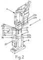
- FIG. 2 shows a device according to FIG Device 25 is provided for supporting a sheet metal part.
- the device 25 is how the foot or head part 2 or 4 modular, so that the support point in all three Directions is adjustable and a simple and rapid design and manufacturing respectively Maintenance is possible.
- Abstützbalken 26 An attached via shims 14 on a flat vertical surface of the foot part 3 Abstweilbalken 26 is constructed in two parts for this purpose, the attachment of the Abstützbalkens is analogous to the upper and the lower portion of the middle part over four screw connections 15a, 15b, 15c, 15d and four fitting pins 16a, 16b, 16c, 16d. of the Two-piece support beam 26 has a lower portion 27 and an upper portion 28th on, which are discontinued at the ends facing each other and by means of one each vertical surface of these paragraphs, normal to the mounting surface of the foot part 3rd aligned, and with the interposition of Shims 14 through each other Bolt 23 a, 23 b and fitting pins 24 a, 24 b are connected.
- a boom 29 for with a corresponding Support surface provided for the body panel viewing support body 30 is provided.
- the same formed horizontal top of the support beam 26 is in turn via shims 14 in analogous way by means of bolts 23a, 23b and fitting pins 24a, 24b with the boom 19 connected.
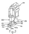
- Figure 3 is a modified embodiment of the device according to the invention 101, which can be used for particularly low clamping positions.
- the device 101 has a foot part 102, a middle part 103 and a head part 104.
- the middle and the head part 103, 104 are, except for the dimensions of the individual Components identical in construction as the like components 3, 4 of the devices according to Figures 1 and 2 and are therefore not explained in detail at this point.
- the foot part 102 is in the embodiment shown in Figure 3 integral with the lower portion 113 of the central portion 103 formed the attachment of the Foot part 103 on the mounting plate or the like. takes place, as in the embodiment according to Figures 1 and 2 by means of four bolts 105a, 105b, 105c, and four washers 107a, 107b, 107c, for adjusting the foot part with respect to the mounting plate in the Directions parallel to this serve.
- the factory provided in the foot part Height adjustment is realized in the embodiment shown by Shims 114, which below the foot in the region of the fastening screws 105a, 105b, 105c are arranged.
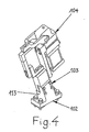
- FIG 4 an embodiment of the embodiment of Figure 3 is shown at which is formed integrally with the foot 103 formed lower portion 113 of the Middle part 103 is arranged inclined, this embodiment is particularly at Lack of space can be used advantageously.
- the inclination of the lower portion 113 can be natural be chosen arbitrarily. Both factory and customer adjustability of the foot and the head part remain unrestricted.
- FIG 6 is a modular device for holding and clamping of sheets for the Body production shown in the automotive industry.
- the modular design Device consists of a foot part 102, a middle part 103 and a head part 104.
- the Foot portion 102 is integral with the as in the embodiment shown in FIG formed lower portion 113 of the central portion 103.
- the foot part 102 can via four fastening screws 105 a, 105 b, 105 c, 105 d, which with a game through (not shown) mounting holes of the foot part 2 are performed, be connected with a mounting plate.
- the adjustment of the foot part 2 with respect to the Mounting plate via washers 107 a, 107 b, 107 c, 107 d, in which the Fixing screws 105a, 105b, 105c, 105d are stored without clearance and after Adjustment of the foot 102 to be welded to this.
- the middle part 103 and the foot part 102 are above flat connecting surfaces, which in present case are arranged vertically, and with the interposition of plane-parallel Plates (shims) 114 of standardized thickness with each other via fastening screws 115a, 115b, 115c, 115d and via fitting pins 116a, 116b.
- shims plane-parallel Plates
- the head part 104 has a holding element 117, which has a flat connecting surface which has an angle via shims 114, an adapter 122 and shims 114 119, which also has a flat connecting surface, is connected.
- the adapter piece 122 is over Fixing screws 123 a, 1234 b connected to the angle 119.
- the second planar connecting surface of the angle 119 is also by means of Fixing screws 125 and fitting pins (not shown) via plane-parallel shims 114 connected to the side surface of the central part 103.
- the holding element 117 also has a level connecting surface which over Shims 114 and corresponding Connecting screws and fitting pins with the clamping lever 120 of a pneumatic Clamping device 121 is connected, which in the illustrated embodiment is fastened by means of fastening screws on an adapter piece 122.
- the head part 104 as a unit solely by the replacement of shims 114 in the region below the adapter piece 122, ie between the foot part 102 and Middle part 103, between the middle part 103 and angle 119 and between angle 119 and Adapter piece 122 is arbitrarily adjustable in all three directions.
- Fig. 6 Due to the modular structure results, as mentioned in Fig. 1, a simple planning and Construction of devices according to the invention.
- Fig. 6 it can be seen that the length the foot part 102, the middle part 103, the adapter piece 122, the holding member 117 without special effort can be constructed and manufactured as desired.
- the Inclination of the angle 119 and the orientation of the connecting surfaces, especially those be arbitrarily aligned between the foot 102 and the middle part 103 to a corresponding adaptation to the complex shape of the to be held or edited Make sheet metal parts.
- FIG. 7 a modular device is shown, whose structure relating to foot 102 and Middle part 103 is analogous to that of FIG. 6.
- the head part 104 has a holding element 117, which has a flat connecting surface which is directly connected to an angle 119. This version will open an adjustment of the head portion 104 omitted in the Z direction.
- the second planar connecting surface of the angle 119 is also by means of Fixing screws 125 and fitting pins (not shown) via plane-parallel shims 114 connected to the side surface of the central part 103.
- the angle 119 is over vertical arranged fastening screws 126 attached to the upper part of the middle part 103.
- fastening screws 120a, 120b a Pin pulling cylinder 221 attached.
- the Stiftziehzylinder can of course arbitrary be oriented, for example, even horizontally.
- the head part 104 as a unit solely by the replacement of shims 114 in the area below the angle 119, that is, between the foot 102 and Middle part 103 and between the middle part 103 and angle 119 in the X and Y directions arbitrarily is adjustable.
- An alternative to the embodiment in FIG. 7 can be achieved by omitting the angle 119, however, the adjustability is lost in one of the directions X or Y, but through Arranging at least one horizontal shim 114 between middle part 103 and Holding element 117 is given an adjustment option in the Z direction.
Landscapes
- Engineering & Computer Science (AREA)
- Mechanical Engineering (AREA)
- Connection Of Plates (AREA)
- Pressure Welding/Diffusion-Bonding (AREA)
- Fats And Perfumes (AREA)
- Electrical Discharge Machining, Electrochemical Machining, And Combined Machining (AREA)
- Automatic Assembly (AREA)
- Devices For Conveying Motion By Means Of Endless Flexible Members (AREA)
- Valve-Gear Or Valve Arrangements (AREA)
- Manipulator (AREA)
- Manufacturing Of Electrical Connectors (AREA)
Claims (24)
- Dispositif modulaire de serrage et/ou de maintien et/ou d'usinage de composants pour le montage industriel, en particulier le montage de carrosseries pour la construction d'automobiles, composé d'une plaque de montage (6) sur laquelle peut être fixé au moins un support (2, 102) sur lequel peut être fixée une pièce intermédiaire verticale (3, 103) portant une pièce de tête réglable (4, 104) munie au moins d'un élément de maintien (17, 117) et/ou au moins d'un élément de serrage actionnable (18, 121) et/ou au moins d'un dispositif d'usinage (221) pour le composant, caractérisé en ce que la pièce intermédiaire verticale (3, 103) est constituée de deux pièces, un élément supérieur et un élément inférieur (12, 13) présentant chacun une surface de jonction plane reliée à l'autre de manière amovible par au moins une plaque à faces planes et parallèles (14, 114) d'épaisseur standard et en ce que l'élément de maintien (17, 117) de la pièce de tête et/ou l'élément de serrage actionnable (18) et/ou le dispositif d'usinage (221) est ou sont reliés de manière amovible avec l'élément de la pièce intermédiaire verticale (3, 103) opposé au support (2, 102) via respectivement au moins deux plaques à faces planes et parallèles (14, 114) d'épaisseur standard formant un angle entre elles et avec la/les plaque(s) à faces planes et parallèles (14, 114) placée(s) entre les surfaces de jonction des deux éléments de la pièce intermédiaire (3, 103).
- Dispositif modulaire de serrage et/ou'de maintien et/ou d'usinage de composants pour le montage industriel, en particulier le montage de carrosseries pour la construction d'automobiles, composé d'une plaque de montage (6) sur lequel peut être fixé au moins un support (2, 102) sur laquelle peut être fixée une pièce intermédiaire verticale (3, 103) portant une pièce de tête réglable (4, 104) munie au moins d'un élément de maintien (17, 117) et/ou au moins d'un élément de serrage actionnable (18, 121) et/ou au moins d'un dispositif d'usinage pour le composant, caractérisé en ce que la pièce intermédiaire verticale (3, 103) est constituée de deux pièces, un élément supérieur et un élément inférieur (12, 13) présentant chacun une surface de jonction plane reliée à l'autre de manière amovible par au moins une plaque à faces planes et parallèles (14, 114) d'épaisseur standard et en ce que l'élément de maintien (17, 117) de la pièce de tête et/ou l'élément de serrage actionnable (18) et/ou le dispositif d'usinage (221) est ou sont reliés de manière amovible avec l'élément de la pièce intermédiaire verticale (3, 103) opposé au support (2, 102) via au moins une plaque à faces planes et parallèles (14, 114) d'épaisseur standard formant un angle avec la/les plaque(s) à faces planes et parallèles (14, 114) placée(s) entre les surfaces de jonction des éléments (12, 13) de la pièce intermédiaire (3, 103).
- Dispositif selon la revendication 1, caractérisé en ce que l'élément de maintien (17, 117) de la pièce de tête (4, 104) est relié à celle-ci via une équerre d'assemblage (19, 119) présentant deux surfaces de jonction formant un angle, dont la première est reliée de manière amovible à l'élément de maintien (17, 117) via au moins une plaque à faces planes et parallèles (14, 114) d'épaisseur standard ou, le cas échéant, via un adaptateur (122) et la seconde à la pièce intermédiaire (3, 103) via au moins une autre plaque à faces planes et parallèles (14, 114) d'épaisseur standard.
- Dispositif selon la revendication 2, caractérisé en ce que l'élément de maintien (17, 117) de la pièce de tête (4, 104) est relié à celle-ci via une équerre d'assemblage (19, 119) présentant deux surfaces de jonction formant un angle, dont la première est reliée de manière amovible à l'élément de maintien (17, 117) via au moins une plaque à faces planes et parallèles (14, 114) d'épaisseur standard ou, le cas échéant, via un adaptateur (122) ou la seconde à la pièce intermédiaire (3, 103) via au moins une plaque à faces planes et parallèles (14, 114) d'épaisseur standard.
- Dispositif selon la revendication 1, caractérisé en ce que l'élément de serrage actionnable (18) présente une surface de jonction plane qui est reliée de manière amovible à un dispositif d'usinage (21) pouvant être alimenté au moyen d'un fluide via au moins une plaque à faces planes et parallèles (14) d'épaisseur standard et en ce que le dispositif d'usinage ou un adaptateur (22) y étant relié présente une autre surface de jonction plane - formant un angle avec la surface de jonction de l'élément de serrage (18) - reliée de manière amovible avec la pièce intermédiaire (3, 103) via au moins une autre plaque à faces planes et parallèles (14) d'épaisseur standard, les surfaces de jonction prévues sur la pièce de tête (4, 104) formant un angle droit avec les surfaces de jonction affectées l'une à l'autre prévues sur l'élément supérieur, respectivement l'élément inférieur de la pièce intermédiaire (3, 103).
- Dispositif selon revendication 5, caractérisé en ce que toujours deux surfaces de jonction formant un angle pour le montage de l'élément de maintien (17) sont parallèles à toujours deux surfaces de jonction formant un angle pour le montage de l'élément de serrage (18).
- Dispositif selon l'une des revendications 1 à 6, caractérisé en ce que le support (2, 102), par rapport à la plaque de montage (6) horizontale en substance, peut être fixé dans deux directions parallèles à la face supérieure de la plaque de montage (6) et que la pièce intermédiaire peut être fixée au support (2, 102) de façon à être réglable en hauteur, le réglage étant effectué par le fabricant et non modifiable
- Dispositif selon l'une des revendications 1 à 7, caractérisé en ce que le support (2, 102) est fixé sur la plaque de montage (6) de manière définitive (non modifiable) via des disques perforés soudables (7a, 7b, 7c, 7d, 107a, 107b, 107c, 107d) pour des boulons d'ancrage (5a, 5b, 5c, 5d, 105a, 105b, 105c, 105d) du support (2, 102).
- Dispositif selon les revendications 7 ou 8, caractérisé en ce que la pièce intermédiaire (3, 103) est réglable par rapport au support (2, 102) via une vis ajustable en hauteur (9) et fixée définitivement (non modifiable) au moyen d'un goujon d'assemblage (11) traversant le support (2, 102) et la pièce intermédiaire (3, 103).
- Dispositif selon l'une des revendications 1 à 9, caractérisé en ce que la pièce intermédiaire (3, 103) a la forme d'une tige à section rectangulaire et en ce que le support (2, 102) présente un creux rectangulaire (8) correspondant, le support (2, 102) étant en contact avec les bords de la pièce intermédiaire (3, 103) via les angles de ce creux.
- Dispositif selon la revendication 9, caractérisé en ce que la pièce intermédiaire (3, 103) n'est en contact avec le support (2, 102) que par l'intermédiaire de deux éléments partiels disposés à distance l'un au-dessus de l'autre.
- Dispositif selon l'une des revendications 1 à 11, caractérisé en ce que l'élément supérieur et l'élément inférieur (12, 13) de la partie intermédiaire (3, 103) présentent un décrochement au niveau de leurs extrémités tournées l'une vers l'autre et que ces décrochements peuvent être vissés l'un à l'autre via la/les plaque(s) à faces planes et parallèles (14, 114) à l'aide de raccords à vis (15a, 15b, 15c, 15d, 115a, 115b, 115c, 115d) et de goujons d'assemblages (16a, 16b, 16c, 16d, 116a, 116b), les surfaces de jonction étant verticales ou présentant au moins un composant vertical en position de fonctionnement.
- Dispositif selon l'une des revendications 1 à 12, caractérisé en ce que la deuxième surface de jonction plane de l'équerre(19, 119) peut être vissée à l'une des surfaces de jonction planes situées sur l'extrémité supérieure de la pièce intermédiaire (3, 103) via la/les plaque(s) à faces planes et parallèles (14, 114) à l'aide de raccords à vis (23a, 23b) et de goujons d'assemblage (24a, 24b), les surfaces de jonction planes étant horizontales ou présentant au moins un composant horizontal en position de fonctionnement.
- Dispositif selon l'une des revendications 1 à 12, caractérisé en ce que la deuxième surface de jonction plane de l'équerre(119) peut être vissée à l'une des surfaces de jonction planes situées sur l'extrémité supérieure de la pièce intermédiaire (103) via la/les plaque(s) à faces planes et parallèles (114) à l'aide de raccords à vis (125) et de goujons d'assemblage, les surfaces de jonction planes étant verticales ou présentant au moins un composant vertical en position de fonctionnement.
- Dispositif selon la revendication 13 ou 14, caractérisé en ce que les deux bras de l'équerre (19, 119) sont perpendiculaires en substance et que la première et la seconde surface de jonction forment un angle droit.
- Dispositif selon la revendication 13 ou 15, caractérisé en ce que la première surface de jonction plane de l'équerre (119) peut être reliée de manière amovible à l'une des surfaces de jonction planes de l'élément de maintien (117) via la/les plaque(s) à faces planes et parallèles (14) à l'aide de raccords à vis (20a, 20b) et de goujons d'assemblage (21a, 21 b), les surfaces de jonction planes étant verticales ou présentant au moins un composant vertical en position de fonctionnement et étant de préférence perpendiculaires aux surfaces de jonction de la pièce intermédiaire (3, 103).
- Dispositif selon la revendication 13 ou 15, caractérisé en ce que la première surface de jonction plane de l'équerre(119) peut être reliée de manière amovible à l'une des surfaces de jonction planes de l'élément de maintien (117) via la/les plaque(s) à faces planes et parallèles (114) ainsi que, le cas échéant, via un adaptateur (122) à l'aide de raccords à vis (120a, 120b, 123a, 123b) et de goujons d'assemblage (121a, 121b), les surfaces de jonction planes étant horizontales ou présentant au moins un composant horizontal en position de fonctionnement et étant de préférence perpendiculaires aux surfaces de jonction de la pièce intermédiaire (103).
- Dispositif selon l'une des revendications 5 à 17, caractérisé en ce qu'un système de commande pneumatique (21) est fixé sur un adaptateur allongé (22) présentant une surface de jonction plane qui peut être fixée sur une surface de jonction plane prévue sur l'extrémité supérieure de la pièce intermédiaire (3, 103) via la/les plaque(s) à faces planes et parallèles (14) à l'aide de raccords à vis et de goujons d'assemblage, les surfaces de jonction planes étant verticales ou présentant au moins un composant vertical en position de fonctionnement et étant de préférence perpendiculaires aux surfaces de jonction des éléments supérieur et inférieur de la pièce intermédiaire (3, 103).
- Dispositif selon la revendication 18, caractérisé en ce que l'élément de commande (20) du système de commande pneumatique (21) présente une surface de jonction plane qui peut être vissée sur la surface de jonction de l'élément de serrage (18) via au moins une plaque à faces planes et parallèles (14) à l'aide de raccords à vis (20a, 20b) et de goujons d'assemblage (21a, 21b), les surfaces de jonction étant perpendiculaires aux surfaces de jonction des éléments supérieur et inférieur de la pièce intermédiaire (3, 103).
- Dispositif selon l'une des revendications 1 à 19, caractérisé en ce que le support (102) et l'élément inférieur de la pièce intermédiaire (103) ne forment qu'une seule pièce.
- Dispositif selon la revendication 20, caractérisé en ce qu'au moins une plaque à faces planes et parallèles d'épaisseur standard (114) est placée entre le support (102) et la plaque de montage (6).
- Dispositif selon la revendication 21, caractérisé en ce que le support (102) est fixé sur la plaque de montage (6) au moyen de boulons de serrage (105a, 105b, 105c) que la/les plaque(s) à faces planes et parallèles(114) est/sont placée(s) dans la zone des boulons de serrage.
- Dispositif selon l'une des revendications précédentes, caractérisé en ce que le tronçon vertical du support (102) relié à l'élément inférieur (113) de la pièce intermédiaire (103) est incliné par rapport à la face supérieure de la plaque de montage (6).
- Processus pour le prémontage, respectivement préréglage et montage final, respectivement réglage final d'un dispositif de serrage et/ou de maintien et/ou d'usinage de composants selon l'une des revendications 1 à 23 pour le montage industriel, plus particulièrement pour le montage de carrosseries lors de la construction d'automobiles, avec une plaque de montage (6) sur laquelle est fixé au moins un support (2, 102), sur lequel est fixée une pièce intermédiaire verticale (3, 103) portant une pièce de tête réglable (4, 104) constituée au moins d'un élément de maintien (17, 117) et au moins d'un élément de serrage actionnable (18, 121), le support (2, 102) et la pièce de tête (4, 104) étant réglables, caractérisé en ce que l'élément de maintien (17, 117) et l'élément de serrage (18, 121) de la pièce de tête sont assemblés de manière amovible par le fabricant lors du prémontage par l'utilisation de plaques à faces planes et parallèles(14, 114) d'épaisseur standard, en ce que le support (2, 102) réglable dans trois directions lors du prémontage et du préréglage par le fabricant est assemblé à la pièce intermédiaire (3, 103), préréglé et fixé de manière définitive (non modifiable), et en ce que les éléments de serrage et de maintien (17, 117, 18, 121) de la pièce de tête (4, 104) réglables dans trois directions par le client lors du montage final et du réglage final sont ajustés le cas échéant en enlevant, en échangeant ou en rajoutant des plaques à faces planes et parallèles(14, 114) d'épaisseur standard via les assemblages amovibles.
Priority Applications (1)
| Application Number | Priority Date | Filing Date | Title |
|---|---|---|---|
| AT00106558T ATE301528T1 (de) | 1999-03-31 | 2000-03-27 | Vorrichtung zum spannen von bauteilen |
Applications Claiming Priority (2)
| Application Number | Priority Date | Filing Date | Title |
|---|---|---|---|
| AT0058099A AT409356B (de) | 1999-03-31 | 1999-03-31 | Vorrichtung zum spannen von bauteilen |
| AT58099 | 1999-03-31 |
Publications (3)
| Publication Number | Publication Date |
|---|---|
| EP1043116A2 EP1043116A2 (fr) | 2000-10-11 |
| EP1043116A3 EP1043116A3 (fr) | 2003-06-25 |
| EP1043116B1 true EP1043116B1 (fr) | 2005-08-10 |
Family
ID=3494354
Family Applications (1)
| Application Number | Title | Priority Date | Filing Date |
|---|---|---|---|
| EP00106558A Expired - Lifetime EP1043116B1 (fr) | 1999-03-31 | 2000-03-27 | Dispositif de serrage pour composants |
Country Status (4)
| Country | Link |
|---|---|
| EP (1) | EP1043116B1 (fr) |
| AT (2) | AT409356B (fr) |
| DE (1) | DE50010899D1 (fr) |
| ES (1) | ES2245626T3 (fr) |
Cited By (1)
| Publication number | Priority date | Publication date | Assignee | Title |
|---|---|---|---|---|
| DE102017103323A1 (de) | 2017-02-17 | 2018-08-23 | Techtory Automation Gmbh | Toleranzausgleichsvorrichtung für eine Spannvorrichtung |
Families Citing this family (7)
| Publication number | Priority date | Publication date | Assignee | Title |
|---|---|---|---|---|
| DE10023598A1 (de) * | 2000-05-15 | 2001-11-22 | Junker & Partner Gmbh | Trägerkopf für eine Halterungsvorrichtung zur Halterung eines Werkstücks |
| DE10310940B4 (de) * | 2003-03-13 | 2017-07-06 | Volkswagen Ag | Einstellbock für die Feineinstellung von Anschlägen |
| DE202006001505U1 (de) * | 2006-02-01 | 2007-06-14 | Staudinger, Karl | Halterung für eine Spanneinheit |
| DE102008053530A1 (de) * | 2008-10-28 | 2010-04-29 | De-Sta-Co Europe Gmbh | Spannvorrichtung |
| DE102011121584A1 (de) * | 2011-12-16 | 2013-06-20 | Audi Ag | Modulares Tragsystem zur Fixierung von Bauteilen |
| DE102013209111B4 (de) * | 2013-05-16 | 2024-01-11 | Fraunhofer-Gesellschaft zur Förderung der angewandten Forschung e.V. | Einspannvorrichtung, insbesondere zur Aufnahme und zum Einspannen eines Bauteils, sowie Einspannsystem mit einer solchen Einspannvorrichtung |
| WO2019201413A1 (fr) * | 2018-04-17 | 2019-10-24 | Multinorm D.O.O. | Appareil de réglage vertical modulaire pour positionner une pièce dans des systèmes de serrage |
Family Cites Families (9)
| Publication number | Priority date | Publication date | Assignee | Title |
|---|---|---|---|---|
| FR2679815A1 (fr) * | 1991-07-30 | 1993-02-05 | Vallemagne Cie | Dispositif de calage en vue du bridage de pieces sur table de machine-outil. |
| US5415383A (en) * | 1992-06-01 | 1995-05-16 | Ausilio; John S. | Clamp arm with slip plane positioning |
| FR2692509B1 (fr) * | 1992-06-22 | 1996-10-18 | Sagnial Expl Ets | Etau de serrage, de sciage et de tendage de materiaux en feuille. |
| DE29509049U1 (de) * | 1995-06-01 | 1995-10-26 | Thyssen Industrie | Vorrichtung zum Einspannen von Bauteilen, insbesondere von Blechen im Zuge einer Schweiß- oder Montagestraße |
| ES2185830T3 (es) * | 1996-04-29 | 2003-05-01 | Emil Bucher Gmbh & Co Modell U | Unidad de sujecion para un sistema modular de sujecion que sostiene piezas de trabajo con geometria compleja, asi como procedimiento para el ajuste de una longitud de base. |
| DE29622739U1 (de) * | 1996-04-29 | 1997-05-28 | Emil Bucher Gmbh & Co Modell U | Spanneinheit für Spannvorrichtungen, die Werkstücke mit komplizierter Geometrie halten |
| DE29717355U1 (de) * | 1997-09-29 | 1997-11-27 | Tuenkers Maschinenbau Gmbh | Bausatz zum modulartigen Aufbau einer aus drei Hauptmodulen aufgebauten Konsole |
| DE29717356U1 (de) * | 1997-09-29 | 1997-11-27 | Tuenkers Maschinenbau Gmbh | Bausatz zum modulartigen Aufbau einer aus drei Hauptmodulen aufgebauten Konsole |
| DE59801477D1 (de) * | 1997-12-17 | 2001-10-18 | Kuka Schweissanlagen Gmbh | Spanneinrichtung für werkstücke |
-
1999
- 1999-03-31 AT AT0058099A patent/AT409356B/de not_active IP Right Cessation
-
2000
- 2000-03-27 ES ES00106558T patent/ES2245626T3/es not_active Expired - Lifetime
- 2000-03-27 DE DE50010899T patent/DE50010899D1/de not_active Expired - Lifetime
- 2000-03-27 AT AT00106558T patent/ATE301528T1/de active
- 2000-03-27 EP EP00106558A patent/EP1043116B1/fr not_active Expired - Lifetime
Cited By (1)
| Publication number | Priority date | Publication date | Assignee | Title |
|---|---|---|---|---|
| DE102017103323A1 (de) | 2017-02-17 | 2018-08-23 | Techtory Automation Gmbh | Toleranzausgleichsvorrichtung für eine Spannvorrichtung |
Also Published As
| Publication number | Publication date |
|---|---|
| ATA58099A (de) | 2001-12-15 |
| EP1043116A3 (fr) | 2003-06-25 |
| DE50010899D1 (de) | 2005-09-15 |
| ES2245626T3 (es) | 2006-01-16 |
| AT409356B (de) | 2002-07-25 |
| ATE301528T1 (de) | 2005-08-15 |
| EP1043116A2 (fr) | 2000-10-11 |
Similar Documents
| Publication | Publication Date | Title |
|---|---|---|
| DE3026174C2 (de) | Vorrichtung zur Besfestigung eines Schließteils an einer Karosserie eines Kraftfahrzeuges | |
| DE10010709C1 (de) | Einstellvorrichtung für einen Cockpitquerträger | |
| EP1925535B1 (fr) | Traverse | |
| DE102009003151A1 (de) | Traganordnung für Solarmodule | |
| DE3927485A1 (de) | Vorrichtung bzw. montagebaugruppe zwischen motor- bzw. antriebseinheit und fahrgestell eines kraftfahrzeugs | |
| DE102017202405A1 (de) | Halteeinrichtung | |
| EP1251038A2 (fr) | Bloc avant avec support d'assemblage pour un véhicule | |
| EP1043116B1 (fr) | Dispositif de serrage pour composants | |
| DE102013209111B4 (de) | Einspannvorrichtung, insbesondere zur Aufnahme und zum Einspannen eines Bauteils, sowie Einspannsystem mit einer solchen Einspannvorrichtung | |
| DE19716805A1 (de) | Positionier-Schnellspannzylinder | |
| EP1613848A1 (fr) | Dispositif de fixation destine a un echangeur thermique et fixation d'echangeur thermique | |
| EP1903219B1 (fr) | Dispositif pour la fixation d'un composant sur un élément de support | |
| EP3536456B1 (fr) | Système de serrage | |
| EP3636363A2 (fr) | Module d'outil pour une installation d'outil à suivre | |
| DE102007045709B3 (de) | Betonschwelle und Verfahren zur Regulierung der Position von Schienen | |
| DE10205541C1 (de) | Spanneinrichtung zum Klemmen von Werkstücken aus Blech | |
| DE10007454C2 (de) | Toleranzausgleich-Element | |
| WO2008148774A1 (fr) | Élément de montage à fixer dans une ou plusieurs rainures en t | |
| DE202016006199U1 (de) | Vorrichtung zum Einsetzen in eine Decke | |
| EP3947236A1 (fr) | Système d'entraînement variable | |
| DE3925167C2 (fr) | ||
| DE2131917A1 (de) | Hoehenverstellbare auflagerung eines maschinengehaeuseteiles an einem auflagekoerper | |
| DE202018006268U1 (de) | Werkzeugmodul für eine Folgeverbund-Werkzeuganlage | |
| EP4263411A1 (fr) | Dispositif de fixation de rail pour des sections de rail de guidage d'un escalier roulant ou d'un trottoir roulant | |
| EP4066688A1 (fr) | Dispositif de fixation de plaques et système de fixation contenant ledit dispositif de fixation de plaques, ainsi que procédé |
Legal Events
| Date | Code | Title | Description |
|---|---|---|---|
| PUAI | Public reference made under article 153(3) epc to a published international application that has entered the european phase |
Free format text: ORIGINAL CODE: 0009012 |
|
| AK | Designated contracting states |
Kind code of ref document: A2 Designated state(s): AT BE CH CY DE DK ES FI FR GB GR IE IT LI LU MC NL PT SE |
|
| AX | Request for extension of the european patent |
Free format text: AL;LT;LV;MK;RO;SI |
|
| RAP1 | Party data changed (applicant data changed or rights of an application transferred) |
Owner name: TMS PRODUKTIONSSYSTEME GMBH |
|
| PUAL | Search report despatched |
Free format text: ORIGINAL CODE: 0009013 |
|
| AK | Designated contracting states |
Designated state(s): AT BE CH CY DE DK ES FI FR GB GR IE IT LI LU MC NL PT SE |
|
| AX | Request for extension of the european patent |
Extension state: AL LT LV MK RO SI |
|
| RIC1 | Information provided on ipc code assigned before grant |
Ipc: 7B 23Q 3/18 B Ipc: 7B 23Q 3/10 A Ipc: 7B 25B 5/00 B |
|
| 17P | Request for examination filed |
Effective date: 20030929 |
|
| AKX | Designation fees paid |
Designated state(s): AT DE ES FR |
|
| GRAP | Despatch of communication of intention to grant a patent |
Free format text: ORIGINAL CODE: EPIDOSNIGR1 |
|
| GRAS | Grant fee paid |
Free format text: ORIGINAL CODE: EPIDOSNIGR3 |
|
| GRAA | (expected) grant |
Free format text: ORIGINAL CODE: 0009210 |
|
| AK | Designated contracting states |
Kind code of ref document: B1 Designated state(s): AT DE ES FR |
|
| REF | Corresponds to: |
Ref document number: 50010899 Country of ref document: DE Date of ref document: 20050915 Kind code of ref document: P |
|
| REG | Reference to a national code |
Ref country code: ES Ref legal event code: FG2A Ref document number: 2245626 Country of ref document: ES Kind code of ref document: T3 |
|
| ET | Fr: translation filed | ||
| RAP2 | Party data changed (patent owner data changed or rights of a patent transferred) |
Owner name: TMS TRANSPORT- UND MONTAGESYSTEME GMBH |
|
| PLBE | No opposition filed within time limit |
Free format text: ORIGINAL CODE: 0009261 |
|
| STAA | Information on the status of an ep patent application or granted ep patent |
Free format text: STATUS: NO OPPOSITION FILED WITHIN TIME LIMIT |
|
| 26N | No opposition filed |
Effective date: 20060511 |
|
| PGFP | Annual fee paid to national office [announced via postgrant information from national office to epo] |
Ref country code: DE Payment date: 20140328 Year of fee payment: 15 |
|
| PGFP | Annual fee paid to national office [announced via postgrant information from national office to epo] |
Ref country code: AT Payment date: 20140326 Year of fee payment: 15 |
|
| REG | Reference to a national code |
Ref country code: DE Ref legal event code: R081 Ref document number: 50010899 Country of ref document: DE Owner name: TMS TURNKEY MANUFACTURING SOLUTIONS GMBH, AT Free format text: FORMER OWNER: TMS PRODUKTIONSSYSTEME GMBH, LINZ, AT Effective date: 20140709 |
|
| PGFP | Annual fee paid to national office [announced via postgrant information from national office to epo] |
Ref country code: ES Payment date: 20140428 Year of fee payment: 15 Ref country code: FR Payment date: 20140328 Year of fee payment: 15 |
|
| REG | Reference to a national code |
Ref country code: ES Ref legal event code: PC2A Owner name: TMS TURNKEY MANUFACTURING SOLUTIONS GMBH Effective date: 20140915 |
|
| REG | Reference to a national code |
Ref country code: FR Ref legal event code: CD Owner name: TMS TURNKEY MANUFACTURING SOLUTIONS GMBH, AT Effective date: 20141016 Ref country code: FR Ref legal event code: TP Owner name: TMS TURNKEY MANUFACTURING SOLUTIONS GMBH, AT Effective date: 20141016 |
|
| REG | Reference to a national code |
Ref country code: AT Ref legal event code: HC Ref document number: 301528 Country of ref document: AT Kind code of ref document: T Owner name: TMS TURNKEY MANUFACTURING SOLUTIONS GMBH, AT Effective date: 20141002 |
|
| REG | Reference to a national code |
Ref country code: DE Ref legal event code: R119 Ref document number: 50010899 Country of ref document: DE |
|
| REG | Reference to a national code |
Ref country code: AT Ref legal event code: MM01 Ref document number: 301528 Country of ref document: AT Kind code of ref document: T Effective date: 20150327 |
|
| REG | Reference to a national code |
Ref country code: FR Ref legal event code: ST Effective date: 20151130 |
|
| PG25 | Lapsed in a contracting state [announced via postgrant information from national office to epo] |
Ref country code: DE Free format text: LAPSE BECAUSE OF NON-PAYMENT OF DUE FEES Effective date: 20151001 |
|
| PG25 | Lapsed in a contracting state [announced via postgrant information from national office to epo] |
Ref country code: AT Free format text: LAPSE BECAUSE OF NON-PAYMENT OF DUE FEES Effective date: 20150327 Ref country code: FR Free format text: LAPSE BECAUSE OF NON-PAYMENT OF DUE FEES Effective date: 20150331 |
|
| REG | Reference to a national code |
Ref country code: ES Ref legal event code: FD2A Effective date: 20160426 |
|
| PG25 | Lapsed in a contracting state [announced via postgrant information from national office to epo] |
Ref country code: ES Free format text: LAPSE BECAUSE OF NON-PAYMENT OF DUE FEES Effective date: 20150328 |