EP1042519B1 - Injector for gas treatment of molten metals - Google Patents
Injector for gas treatment of molten metals Download PDFInfo
- Publication number
- EP1042519B1 EP1042519B1 EP98960964A EP98960964A EP1042519B1 EP 1042519 B1 EP1042519 B1 EP 1042519B1 EP 98960964 A EP98960964 A EP 98960964A EP 98960964 A EP98960964 A EP 98960964A EP 1042519 B1 EP1042519 B1 EP 1042519B1
- Authority
- EP
- European Patent Office
- Prior art keywords
- rotor
- cavity
- gas
- passages
- molten metal
- Prior art date
- Legal status (The legal status is an assumption and is not a legal conclusion. Google has not performed a legal analysis and makes no representation as to the accuracy of the status listed.)
- Expired - Lifetime
Links
Images


Classifications
-
- F—MECHANICAL ENGINEERING; LIGHTING; HEATING; WEAPONS; BLASTING
- F27—FURNACES; KILNS; OVENS; RETORTS
- F27D—DETAILS OR ACCESSORIES OF FURNACES, KILNS, OVENS, OR RETORTS, IN SO FAR AS THEY ARE OF KINDS OCCURRING IN MORE THAN ONE KIND OF FURNACE
- F27D27/00—Stirring devices for molten material
-
- B—PERFORMING OPERATIONS; TRANSPORTING
- B01—PHYSICAL OR CHEMICAL PROCESSES OR APPARATUS IN GENERAL
- B01F—MIXING, e.g. DISSOLVING, EMULSIFYING OR DISPERSING
- B01F23/00—Mixing according to the phases to be mixed, e.g. dispersing or emulsifying
- B01F23/20—Mixing gases with liquids
- B01F23/23—Mixing gases with liquids by introducing gases into liquid media, e.g. for producing aerated liquids
- B01F23/233—Mixing gases with liquids by introducing gases into liquid media, e.g. for producing aerated liquids using driven stirrers with completely immersed stirring elements
- B01F23/2331—Mixing gases with liquids by introducing gases into liquid media, e.g. for producing aerated liquids using driven stirrers with completely immersed stirring elements characterised by the introduction of the gas along the axis of the stirrer or along the stirrer elements
-
- B—PERFORMING OPERATIONS; TRANSPORTING
- B01—PHYSICAL OR CHEMICAL PROCESSES OR APPARATUS IN GENERAL
- B01F—MIXING, e.g. DISSOLVING, EMULSIFYING OR DISPERSING
- B01F23/00—Mixing according to the phases to be mixed, e.g. dispersing or emulsifying
- B01F23/20—Mixing gases with liquids
- B01F23/23—Mixing gases with liquids by introducing gases into liquid media, e.g. for producing aerated liquids
- B01F23/233—Mixing gases with liquids by introducing gases into liquid media, e.g. for producing aerated liquids using driven stirrers with completely immersed stirring elements
- B01F23/2336—Mixing gases with liquids by introducing gases into liquid media, e.g. for producing aerated liquids using driven stirrers with completely immersed stirring elements characterised by the location of the place of introduction of the gas relative to the stirrer
- B01F23/23364—Mixing gases with liquids by introducing gases into liquid media, e.g. for producing aerated liquids using driven stirrers with completely immersed stirring elements characterised by the location of the place of introduction of the gas relative to the stirrer the gas being introduced between the stirrer elements
-
- B—PERFORMING OPERATIONS; TRANSPORTING
- B01—PHYSICAL OR CHEMICAL PROCESSES OR APPARATUS IN GENERAL
- B01F—MIXING, e.g. DISSOLVING, EMULSIFYING OR DISPERSING
- B01F27/00—Mixers with rotary stirring devices in fixed receptacles; Kneaders
- B01F27/80—Mixers with rotary stirring devices in fixed receptacles; Kneaders with stirrers rotating about a substantially vertical axis
- B01F27/81—Mixers with rotary stirring devices in fixed receptacles; Kneaders with stirrers rotating about a substantially vertical axis the stirrers having central axial inflow and substantially radial outflow
- B01F27/811—Mixers with rotary stirring devices in fixed receptacles; Kneaders with stirrers rotating about a substantially vertical axis the stirrers having central axial inflow and substantially radial outflow with the inflow from one side only, e.g. stirrers placed on the bottom of the receptacle, or used as a bottom discharge pump
-
- B—PERFORMING OPERATIONS; TRANSPORTING
- B01—PHYSICAL OR CHEMICAL PROCESSES OR APPARATUS IN GENERAL
- B01F—MIXING, e.g. DISSOLVING, EMULSIFYING OR DISPERSING
- B01F27/00—Mixers with rotary stirring devices in fixed receptacles; Kneaders
- B01F27/80—Mixers with rotary stirring devices in fixed receptacles; Kneaders with stirrers rotating about a substantially vertical axis
- B01F27/94—Mixers with rotary stirring devices in fixed receptacles; Kneaders with stirrers rotating about a substantially vertical axis with rotary cylinders or cones
- B01F27/941—Mixers with rotary stirring devices in fixed receptacles; Kneaders with stirrers rotating about a substantially vertical axis with rotary cylinders or cones being hollow, perforated or having special stirring elements thereon
-
- C—CHEMISTRY; METALLURGY
- C22—METALLURGY; FERROUS OR NON-FERROUS ALLOYS; TREATMENT OF ALLOYS OR NON-FERROUS METALS
- C22B—PRODUCTION AND REFINING OF METALS; PRETREATMENT OF RAW MATERIALS
- C22B21/00—Obtaining aluminium
- C22B21/06—Obtaining aluminium refining
- C22B21/064—Obtaining aluminium refining using inert or reactive gases
-
- C—CHEMISTRY; METALLURGY
- C22—METALLURGY; FERROUS OR NON-FERROUS ALLOYS; TREATMENT OF ALLOYS OR NON-FERROUS METALS
- C22B—PRODUCTION AND REFINING OF METALS; PRETREATMENT OF RAW MATERIALS
- C22B9/00—General processes of refining or remelting of metals; Apparatus for electroslag or arc remelting of metals
- C22B9/05—Refining by treating with gases, e.g. gas flushing also refining by means of a material generating gas in situ
-
- B—PERFORMING OPERATIONS; TRANSPORTING
- B01—PHYSICAL OR CHEMICAL PROCESSES OR APPARATUS IN GENERAL
- B01F—MIXING, e.g. DISSOLVING, EMULSIFYING OR DISPERSING
- B01F23/00—Mixing according to the phases to be mixed, e.g. dispersing or emulsifying
- B01F23/20—Mixing gases with liquids
- B01F23/23—Mixing gases with liquids by introducing gases into liquid media, e.g. for producing aerated liquids
- B01F23/233—Mixing gases with liquids by introducing gases into liquid media, e.g. for producing aerated liquids using driven stirrers with completely immersed stirring elements
- B01F23/2331—Mixing gases with liquids by introducing gases into liquid media, e.g. for producing aerated liquids using driven stirrers with completely immersed stirring elements characterised by the introduction of the gas along the axis of the stirrer or along the stirrer elements
- B01F23/23311—Mixing gases with liquids by introducing gases into liquid media, e.g. for producing aerated liquids using driven stirrers with completely immersed stirring elements characterised by the introduction of the gas along the axis of the stirrer or along the stirrer elements through a hollow stirrer axis
-
- B—PERFORMING OPERATIONS; TRANSPORTING
- B01—PHYSICAL OR CHEMICAL PROCESSES OR APPARATUS IN GENERAL
- B01F—MIXING, e.g. DISSOLVING, EMULSIFYING OR DISPERSING
- B01F23/00—Mixing according to the phases to be mixed, e.g. dispersing or emulsifying
- B01F23/20—Mixing gases with liquids
- B01F23/23—Mixing gases with liquids by introducing gases into liquid media, e.g. for producing aerated liquids
- B01F23/233—Mixing gases with liquids by introducing gases into liquid media, e.g. for producing aerated liquids using driven stirrers with completely immersed stirring elements
- B01F23/2331—Mixing gases with liquids by introducing gases into liquid media, e.g. for producing aerated liquids using driven stirrers with completely immersed stirring elements characterised by the introduction of the gas along the axis of the stirrer or along the stirrer elements
- B01F23/23314—Mixing gases with liquids by introducing gases into liquid media, e.g. for producing aerated liquids using driven stirrers with completely immersed stirring elements characterised by the introduction of the gas along the axis of the stirrer or along the stirrer elements through a hollow stirrer element
-
- B—PERFORMING OPERATIONS; TRANSPORTING
- B01—PHYSICAL OR CHEMICAL PROCESSES OR APPARATUS IN GENERAL
- B01F—MIXING, e.g. DISSOLVING, EMULSIFYING OR DISPERSING
- B01F23/00—Mixing according to the phases to be mixed, e.g. dispersing or emulsifying
- B01F23/20—Mixing gases with liquids
- B01F23/23—Mixing gases with liquids by introducing gases into liquid media, e.g. for producing aerated liquids
- B01F23/233—Mixing gases with liquids by introducing gases into liquid media, e.g. for producing aerated liquids using driven stirrers with completely immersed stirring elements
- B01F23/2335—Mixing gases with liquids by introducing gases into liquid media, e.g. for producing aerated liquids using driven stirrers with completely immersed stirring elements characterised by the direction of introduction of the gas relative to the stirrer
- B01F23/23352—Mixing gases with liquids by introducing gases into liquid media, e.g. for producing aerated liquids using driven stirrers with completely immersed stirring elements characterised by the direction of introduction of the gas relative to the stirrer the gas moving perpendicular to the axis of rotation
Definitions
- This invention relates generally to the treatment of molten metals with gases prior to casting or other processes involving metal cooling and solidification, to remove dissolved gases (particularly hydrogen), non-metallic solid inclusions and unwanted metallic impurities prior to cooling and solidification of the metal. More particularly, the invention relates to gas injectors, and apparatus employing such injectors, used for the treatment of molten metals in this way.
- molten aluminum and aluminum alloys derived from alumina reduction cells or metal holding furnaces usually contain dissolved hydrogen, solid non-metallic inclusions (e.g. TiB 2 , aluminum/magnesium oxides, aluminum carbides, etc.) and various reactive elements, e.g. alkali and alkaline earth metals.
- solid non-metallic inclusions e.g. TiB 2 , aluminum/magnesium oxides, aluminum carbides, etc.
- various reactive elements e.g. alkali and alkaline earth metals.
- Non-metallic solid inclusions reduce metal cleanliness, and the reactive elements and inclusions create unwanted metal characteristics.
- This process is often referred to as "metal degassing," although it will be appreciated from the above description that it may be used for more than just degassing of the metal.
- the process is typically carried out in one of two ways: in the furnace, normally using one or more static gas injection tubes; or in-line, by passing the metal through a box situated in the trough normally provided between a holding furnace and the casting machine so that more effective gas injectors can be used.
- the process is inefficient and time consuming because large gas bubbles are generated, leading to poor gas/metal contact, poor metal stirring and high surface turbulence and splashing. Dross formation and metal loss result from the resulting surface turbulence, and poor metal stirring results in some untreated metal.
- the second method (as used in various currently available units) is more effective at introducing and using the gas. This is in part because the in-line method operates as a continuous process rather than a batch process.
- the gas bubbles must be in contact with the melt for a suitable period of time and this is achieved by providing a suitable depth of molten metal above the point of injection of the gas, and by providing a means of breaking up the gas into smaller bubbles and dispersing the smaller bubbles more effectively through the volume of the metal, for example by means of rotating dispersers or other mechanical or non-mechanical devices.
- Metal residence times in the containers in which such degassing operations are performed are often in excess of 200 seconds, and frequently in excess of 300 seconds.
- Effectiveness of degassing is frequently defined in terms of the hydrogen degassing reaction for aluminum alloys and an adequate reaction is generally considered to be one achieving at least 50% hydrogen removal (typically 50 to 60%). This results in the need for deep treatment boxes of large volume (often holding three or more tons of metal) which are unfortunately not self-draining when the metal treatment process is terminated. This gives rise to operational problems and the generation of waste because metal remains in the treatment boxes when the casting process is stopped for any reason and solidifies in the boxes if not removed or kept molten by heaters.
- the reservoir of a former metal or alloy in a box (unless it can be tipped and emptied) undesirably affects the composition of the next metal or alloy passed through the box until the reservoir of the former metal is depleted.
- the entry and exit sections of such degasser boxes generally have cross-sectional areas (measured in a vertical plane orientated transversely to the direction of metal flow) substantially less than the corresponding cross-sectional area of the degasser box itself in order to match the cross-sectional area of the metallurgical troughs used to feed metal to and remove metal from the degasser box.
- Modern degassers of this type generally use less than one litre of gas per kilogram (Kg) of metal treated. In spite of extensive development of dispersers to achieve greater mixing efficiency, such equipment remains large, with metal contents of at least 0.4 m 3 and frequently 1.5 m 3 or more being required.
- One or more dispersers such as the rotary dispersers previously mentioned may be used, but for effective degassing, at least 0.4 m 3 of metal must surround each disperser during operation.
- U.S. Patent 5,527,381 to Waite et al. describes a degasser in which the box-like structure of the earlier devices is replaced by a section of trough having approximately the same cross-sectional area as the metallurgical troughs feeding and removing metal from the degasser. This creates a degasser of smaller volume and one which retains little if any metal when the source of metal is interrupted after the degassing operation is completed (i.e. it is substantially self-draining along with the trough).
- the degasser uses several relatively small rotary gas injectors along the length of a trough section to achieve the equivalent of a continuous "plug" flow reactor, giving a high degassing efficiency.
- U.S. patent 2,743,914 issued on May 1, 1956 to Epprecht discloses a mixing apparatus for mixing gases and liquids.
- this device is not intended for introducing a gas into molten metal and it would be difficult to make such a structure from a refractory material, e.g. graphite, suitable for use with molten metals.
- the apparatus also relies on the production of a venturi effect by forcing a liquid through constricted passages. It is not at all clear that such a structure would be effective with molten metals which are of high density.
- European patent application 0 365 013 which was published on April 25, 1990 in the name of Showa Aluminum Corporation discloses a device for releasing and diffusing bubbles in a liquid, specifically a molten metal.
- this device is designed as an agitator and has a number of liquid agitating projections spaced around the periphery to creat a stirring action intended for a deep box degasser. The device is therefore not suitable for use in trough-like vessels of the type to which the present invention relates.
- all degassing . apparatus must deliver a certain minimum volume of gas per kilogram of metal, and in a trough-like vessel where the residence time of the metal in the region in which the gas is supplied is substantially less than in the deep box degassers, the amount of gas which each rotary injector must deliver is high and the ability to deliver a suitable amount of gas determines the effectiveness of an injector design.
- An object of the present invention is to provide a gas injector of the kind that may be used for in-line degassing of molten metal in a shallow trough, which injector has a reduced tendency to emit gas unevenly during normal use.
- Another object of the invention is to provide a molten metal degassing apparatus which can be operated efficiently and without substantial splashing of gas at the molten metal surface.
- Another object of the invention is to provide a gas injector and a molten metal degassing apparatus that can treat molten metal held in containers of shallow depth while achieving thorough degassing without undue splashing of the metal.
- Another object is to provide a method of degassing metal in a shallow trough-like vessel with little splashing and uneven metal treatment.
- an injector for injection gas under pressure into a molten metal.
- the injector includes a rotor that is rotatable about an axis of rotation, and has a cylindrical projection-free side surface, a bottom surface, and an internal cavity for receiving molten metal located centrally of the rotor with respect to the axis of rotation, a plurality of openings in the side surface spaced around the rotor for ejecting molten metal and gas from said rotor upon rotation of said rotor about said axis of rotation, at least one opening in the bottom surface communicating with the cavity permitting entry of molten metal into said cavity, a plurality of passages disposed in the rotor interconnecting the cavity and the openings in the side surface.
- each passage has an intermediate step formed by an internal surface that extends generally upwardly in a direction from said central cavity to said outer surface.
- Each said outlet of said gas passageway is positioned in said internal surface.
- a gas passageway for introducing gas into molten metal present within the rotor is also provided.
- the gas passageway lacking direct communication with the cavity, has at least one outlet opening into at least one of the plurality of passages.
- the cavity has an upper surface and each of the passages has an upper surface, wherein, in an operational orientation of the injector, at least radially outer parts of the upper surfaces of the passages are positioned higher in the rotor than the upper surface of said cavity, and wherein the at least one outlet is positioned in the at least one of the plurality of passages at position(s) located vertically higher than the upper surface of the cavity.
- a molten metal degassing apparatus including a trough for conveying molten metal from an inlet to an outlet, and at least one gas injector positioned within the trough submerged, in use, in the molten metal; wherein the at least one gas injector is an injector as defined above.
- a method of injecting gas into a molten metal includes the step of: furnishing an injector having a rotor that is rotatable about an axis of rotation, the rotor having a cylindrical projection-free side surface, a bottom surface, and an internal cavity, for receiving molten metal located centrally of the rotor with respect to the axis of rotation, a plurality of openings in the side surface spaced around the rotor for ejecting molten metal and gas from the rotor upon rotation of the rotor about the axis of rotation, at least one opening in the bottom surface communicating with the cavity permitting entry of molten metal into the cavity, a plurality of passages disposed in the rotor interconnecting the cavity and the openings in the side surface, said passages being open along the entire bottom surface of the rotor, each passage having an intermediate step formed by an internal surface that extends generally upwardly in a direction from said central cavity to said outer surface,
- the cavity has an upper surface and each of said passages has an upper surface, wherein, in an operational orientation of the injector, at least radially outer parts of the upper surfaces of the passages are positioned higher in the rotor than the upper surface of the cavity, and wherein the at least one outlet is positioned in the at least one of the plurality of passages at position(s) located in said internal surface vertically higher than the upper surface of said cavity.
- the rotor is then immersed in a quantity of molten metal, so that molten metal fills the cavity and the passages.
- Gas is supplied to the molten metal present within the rotor via the gas passageway; and the rotor is rotated to cause the gas to be broken into bubbles and a gas-metal mixture to be ejected from the openings in the side surface.
- the gas is not supplied to the cavity, but is supplied to the outlet in the at least one of the passages positioned vertically higher than the upper surface of the cavity.
- the cavity for receiving the molten metal has at least a portion on the axis of rotation that is free of obstructions and insertions, i.e. that is unoccupied free volume, and preferably is in the form of an empty cylindrical space centred on the axis of rotation.
- the gas injector of the present invention is similar to the injectors of the Waite et al. patent mentioned above, but it is distinguished by a lack of direct communication with the central cavity in the rotor and by at least one, and usually numerous, gas outlets opening into the passages interconnecting the central cavity with the side outlets.
- the injector of the present invention is believed to provide even gas distribution by avoiding a collection of gas which is believed to take place within the central cavity of the prior rotor.
- the design of the rotor of the present invention is believed to maintain (or even enhance) the metal pumping action created upon rotation of the rotor. When gas is delivered into the central cavity of the rotor, gas appears to be held in this area.
- the retained gas can eventually fill the entire cavity and impede the metal pumping action and at the same time create large bubbles that are released suddenly and unpredictably, causing splashing at the surface of the molten metal, particularly when the rotor is used in shallow troughs.
- the introduced gas is rapidly swept along the passages to the outlets by the outwardly flowing metal.
- the entire cavity can be filled with metal, which ensures that the pumping action of the metal (molten metal entering the cavity through the opening in the bottom wall to be pumped out through the passages by the rotation motion) is maximized.
- higher rates of gas flow can be achieved per rotor and the same number of rotors can degas metal having a lower residence time (higher metal flow) in the degassing section of the apparatus.
- the cavity in the rotor has an upper surface and each of the passages has an upper surface (at least in radially outer regions of the passages), such that, in the operational orientation of the injector, the upper surfaces of the passages are positioned higher in the rotor than the upper surface of the cavity, and the gas outlets are located in the passages at positions higher than the upper surface of the cavity.
- the gas emanating from the outlets not only has to move against the direction of metal flow through the passages, but also has to move downwardly against a considerable (given the difference in density between gas and molten metal) buoyancy force.
- the gas outlets provided in the passages preferably each face in a direction that is orientated at an angle with respect to the axis of rotation of the rotor towards the side surface of the rotor, i.e. the outlets do not face downwardly, but rather horizontally or at an angle between the vertical and the horizontal (by the term "face” used in connection with such outlets, we mean that the outlets tend to direct gas in the direction in which they "face”, at least when surrounded by air - i.e. if an outlet directs gas horizontally, it "faces" the horizontal).
- each passage with an intermediate step (an upward step when travelling in a direction from the central cavity to the side surface of the rotor) formed by an internal surface that extends parallel to, or at an angle to, the axis of rotation of the rotor, and positioning each opening of the gas passageway in the internal surface so that the openings face outwardly towards the side surface of the rotor.
- This not only has the effect of injecting the gas in a direction of travel towards the rotor outlets, but also provides a barrier against reverse movement of the gas along the passage to the central cavity.
- a bubble of gas must travel in a downward direction against the considerable buoyancy force acting upon it from the surrounding metal. The gas is therefore even less likely to travel to and accumulate in the central cavity.
- the injector of the present invention may be similar to the injectors shown in the Waite et al. patent. That is to say, the passages extend to the bottom face of the rotor and are open along the entire bottom face. The parts of the rotor between the passages form isolated downward wedge-like projections from the upper end of the rotor and these projections resemble, and are usually referred to, as "vanes.” Alternatively, the passages may extend only part way to the bottom surface and thus be closed at this surface, in which case the rotor does not have freestanding vanes, but rather closed vanes.
- the gas delivery outlets are preferably symmetrically disposed around the rotor, so that the passages are also symmetrically disposed.
- the rotor may have an upper surface that is flat, convex or conical and that is most preferably smooth and projection-free to avoid splashing or vortex formation at the surface.
- the rotor is preferably mounted at the lower end of a rotatable concentric shaft and the gas passageway preferably extends through the shaft into the rotor but not, as noted, into the cavity.
- the diameter of the rotor is 9 cm (3.5 inches) to 15.25 cm (6 inches), the rotor opening swept area (the area of the surface that the outlets sweep past as the rotor rotates) is preferably 60% or less.
- the number of passages (vanes) in the rotor is normally greater than 4, and preferably greater than 6, and the vanes within the rotor preferably come to an acute angle at the periphery of the central cavity.
- the injector is normally operated at a rotational speed within the range of 500 to 1200 rpm.
- the height of sides of rotor are preferably made as small as possible, preferably less than 10 cm.
- a molten metal degassing apparatus comprising: a trough-like container for conveying molten metal from an inlet to an outlet, and at least one gas injector positioned within the container submerged, in use, in the molten metal, wherein said at least one gas injector is as defined above according to the invention.
- the trough-like container has a width of less than 60 cm and preferably has a static to dynamic metal holdup of less than 30%, preferably less than 15% and optimally substantially zero.
- the dynamic metal holdup of the container is defined as the amount of metal in the treatment zone (the region around the injector(s), i.e. between the first and the last injectors, when there is more than one injector present in the apparatus) when the gas injectors are in operation, while the static metal holdup is defined as the amount of metal that remains in the treatment zone when the source of metal has been removed and the metal is allowed to drain naturally from the treatment zone.
- the trough-like container is normally positioned within a metal conveying trough, so the inlet and outlet have dimensions similar to that of the remainder of the trough.
- the trough may have a greater cross-section (depth), but this should be minimized.
- the trough depth is specified by the metal carrying capacity (level of metal under normal operating conditions) and is normally less than about 50 cm and preferably less than 30 cm.
- the number of injectors arranged in a row in the trough depends on the degree of degassing to be achieved. Usually, there are at least 2 such injectors.
- the injectors are placed so that the bottom face of an injector is generally less than about 2 cm from the bottom of the trough, more preferably less than about 0.5 cm from the trough bottom.
- the injectors of the present invention can be positioned closer to the bottom wall of the trough-like container than the conventional injector, so a greater degassing effect can be achieved due to the extra depth of molten metal through which the gas bubbles must rise when exiting the injector.
- gas is kept out of the cavity of the rotor by designing the rotor in the manner indicated above and supplying the gas only to the passages and not to the cavity itself.
- Figures 1 and 2 show an embodiment of a rotary gas injector 10 which does not form part of the present invention.
- the injector consists of a smooth faced rotor 11 attached to a bottom end of a cylindrical shaft 12.
- the rotor 11 is in the form of an upright lower cylindrical portion 13, having an outer surface forming a side face 14, and an upper conical upper portion 15 provided with a smooth surface 16.
- the lower cylindrical portion 13 is provided with a centrally-located cylindrical cavity 18, open at a bottom surface 21 of the rotor 11 where the lower end of the cavity consequently forms an opening in the bottom surface.
- the cavity 18 extends upwardly from the bottom surface of the rotor to an upper cavity surface 19, located at the same horizontal level as an upper edge 20 of the lower cylindrical portion 13 where it joins the conical upper portion 15.
- passages 22 extend radially from the central cavity 18 to openings forming outlets 23 positioned in the outer face 14 of the lower portion of the rotor 13.
- the passages 22 are defined between generally triangular wedge-like solid sections of the rotor body forming vanes 25.
- the passages 22 are open at the bottom surface 21 of the lower portion of the rotor and extend upwardly to the same extent as the cavity 18, terminating in upper surfaces 26.
- a gas passageway 30 terminates at its lower end at a location 31 within the conical upper portion 15 of the rotor 11, so that it does not extend into the cylindrical cavity 18, i.e. it does not penetrate the upper cavity surface 19.
- a series of smaller gas passageways 32 extend outwardly and downwardly from the lower end 31 of the gas passageway 30 to openings forming outlets 35 in upper surfaces 26 of the passages 22.
- the injector 10 is immersed in molten metal and rotated at a suitable speed. Gas is forced into the passageway 30 at sufficient pressure to emerge from outlets 35. As the injector rotates, molten metal within the central cavity 18 is caused to move along passages 22 to emerge from outlets 23. Air bubbles emerging from outlets 35 are entrained within the metal and are moved to the outlets 23. A region of high mechanical shear is created at the outer surface 14 of the rotor 11 where jets of molten metal emerging from the outlets 23 encounter relatively static molten metal surrounding the rotor. As the gas bubbles entrained in the jets pass through the high shear region, they are broken down into bubbles of extremely small size and are efficiently dispersed over a wide area by the metal jets.
- the trough in which the rotors are installed is filled to its normal operating level with molten metal, and the rotors are rotated at high speed (e.g. 500 to 1200 rpm).
- This action causes metal within the central cylindrical cavity 18 and passages 22 to flow radially outwardly through the side openings 23. Fresh metal is then drawn into the central cavity.
- Gas is supplied by the gas passageway 30 to one or more of the injectors and is delivered to the passages 22 as gas bubbles in the metal without flowing directly into the central cylindrical cavity 18.
- the metal flowing through the passages carries the bubbles to the outer face of the rotor where, as noted above, the high rotational speed shears the bubbles into finer bubbles which are then dispersed by the horizontally moving metal.
- the gas is dispersed with little turbulence, making the gas injector highly effective for the trough-like degasser vessel.
- a rotor of the present invention when viewed from the top, appears to have a continuous circular outline, with no projections, vanes or other devices extending radially beyond the upper conical portion 15 that agitate the surrounding metal to cause excessive turbulence in the trough.
- the gas is not delivered to the central cavity, so that there is no tendency for it to collect there, and hence no tendency to reduce the pumping efficiency or generate turbulence, even at high gas delivery rates.
- FIGs 3, 4 and 5 show a preferred embodiment of the rotary gas injector of the present invention.
- the injector has many of the same general features as the embodiment of Figures 1 and 2. However, this embodiment differs in the following ways.
- the central cavity 18 has an upper surface 19 positioned below the edge 20 where the lower cylindrical portion 13 joins the upper conical portion 15. Nevertheless, the passages 22 extend upwardly to their upper surfaces 26 positioned at the level of the edge 20. Therefore, a vertical radially outwardly-facing step 38 is formed between the upper surface 19 of the central cavity 18 and the upper surfaces 26 of the radial passages 22.
- Axial gas passageway 30 in the cylindrical shaft 12 continues into the rotor 11 for a short distance, terminating at a location 31 such that the passageway does not extend to the upper end 19 of the cylindrical cavity 18.
- a series of small horizontal gas passageways 32 connect the end of the gas vertical passageway 30 with each of the gas outlets 35, so that gas flowing into the gas injector through passageway 30 is distributed directly into the passages 22 and not to the centrally located cylindrical cavity 18.
- the outlets 35 are positioned in the vertical step 38 short distance above the upper end 19 of the cavity.
- FIG. 6 shows a further preferred embodiment of the rotary gas injector of the present invention.
- the injector has the same general features as in the preceding embodiments.
- the upper surface 19 of the centrally located cylindrical cavity 18 in this embodiment is defined by a horizontal baffle plate 40, having the same diameter as the central cavity 18, fixed between the inner edges of the triangular vanes 25.
- a gas passageway 30 emerges at its lower end into the space 41 above the baffle plate 40. Gas entering this space is forced between the upper ends of the vanes 25 and thus directly into the passages 22 positioned between the vanes.
- This embodiment therefore works in much the same way as the embodiment of Figs. 3, 4 and 5, except that the gas outlets 35 of that embodiment occupy essentially the entire vertical surface of the step 38.
- This embodiment is of interest because it amounts to a way of converting injectors of prior US patent 5,527,381 into injectors according to the present invention, i.e. by attaching baffle plates within the central cavity 18 at the towards the upper end of the cavity.
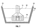
- FIG. 7 shows a rotary injector 10 of the present invention within a cross-section of a metallurgical trough 50 which forms a metal container for degassing operations carried out according to the present invention.
- troughs are generally elongated troughs fabricated from metal and lined with a refractory material that is resistant to molten metal.
- the trough 50 in the present invention is used as a portion of a longer metal delivery trough located between a source of metal (such a holding furnace) and a sink for metal (such as a DC casting machine or continuous casting machine for plate or rod).
- a normal metal level 52 which is the metal level in the trough when it is connected to the source and sink of metal for which it is designed, and is operated at a safe metal level (to prevent accidental metal spills, for example).
- the normal metal level is generally close to a top edge 53 of the trough for economic reasons.
- Figure 8 shows a complete degasser unit according to a preferred form of the present invention taken in longitudinal section along the centre line of the rotor shown in Figure 7.
- the degasser unit as illustrated consists of four rotary gas injectors 10 provided in series along the central longitudinal axis of the metallurgical trough section. However, the number of injectors may be greater or less than this number. Typically from 2 to 10 injectors may be used, preferably 4 to 8 injectors. The distance between the centre-line of the first injector and the last injector of the series is defined as the "treatment section" length illustrated by arrow 54.
- the trough 57 depicted in Figure 8 is shown with a deeper section 50 in the area of the injectors 10.
- the metal will drain (generally in the direction of metal flow (arrow 56) unless alternate draining procedures are used).
- an amount of metal shown by the level 55 will be retained in this section.
- This is referred to as the "metal holdup" and is defined as the ratio of the volume of metal that remains in the degasser trough after the metal has naturally drained out and the amount present during normal operations. This can be determined practically by determining the amount of metal within the "treatment section" as defined above during normal operation and after the metal had drained from the trough as much as possible by natural drainage.
- this would be the ratio of the cross sectional area of the trough below line 55 times the distance between the first and final rotors, and the cross-sectional area of the trough below line 52 times the same distance.
- this ratio should be less than 30%, more preferably less than 15%.
- Most preferably the ratio is zero indicating that the treatment section does not have a deeper section such as illustrated in Figure 8 and therefore drains completely by natural drainage after the metal source is interrupted. Such an embodiment is illustrated in Figure 9.
- a degasser based on the injector embodiment of Figures 3,4 and 5 was modelled using a water model, in which the gas bubbles could be observed directly and the surface turbulence measured.
- a rotor having a diameter of 4.5 inches was used and it was operated at 800 rpm.
- prior art rotors were tested, in which the gas was delivered by a single outlet to the centre of the centrally located cylindrical cavity.
- the prior art rotors had diameters of 4, 4.5 and 5 inches and were also operated at the same speed. All rotors delivered the same flow rate of gas (nitrogen was used) at a flow rate of 137 litre/minute.
- This flow rate was about three time higher than the typical gas delivery rate when the rotor was used in molten metal and was required to correctly compensate for the gas expansion which occurs at the metal temperatures experienced in the actual degasser of the present type.
- the relative surface turbulence measured by a surface contact device, was determined and is shown plotted versus rotor diameter in Figure 10.
- the prior art turbulence is shown as a segmented line 60; and the present invention by a point 61.
- the surface turbulence increases with the diameter of the rotor, but the rotor of the present invention shows improvement over a prior art rotor of equivalent size.
- FIGS 11A and 11B The bubble generation by the present rotor and prior art device is shown in Figures 11A and 11B. These Figures show that bubbles in the prior art injector are retained in the central region of the rotor (Fig. 11(A)), whereas in the injector of the present invention (Fig. 11(B), the bubbles are fully dispersed and, as a result, turbulence and uneven pumping action are avoided.
Landscapes
- Chemical & Material Sciences (AREA)
- Engineering & Computer Science (AREA)
- Chemical Kinetics & Catalysis (AREA)
- Mechanical Engineering (AREA)
- Manufacturing & Machinery (AREA)
- Materials Engineering (AREA)
- Metallurgy (AREA)
- Organic Chemistry (AREA)
- General Engineering & Computer Science (AREA)
- Manufacture And Refinement Of Metals (AREA)
- Turbine Rotor Nozzle Sealing (AREA)
- Waste-Gas Treatment And Other Accessory Devices For Furnaces (AREA)
Applications Claiming Priority (3)
| Application Number | Priority Date | Filing Date | Title |
|---|---|---|---|
| US997899 | 1997-12-24 | ||
| US08/997,899 US6056803A (en) | 1997-12-24 | 1997-12-24 | Injector for gas treatment of molten metals |
| PCT/CA1998/001152 WO1999034024A1 (en) | 1997-12-24 | 1998-12-11 | Injector for gas treatment of molten metals |
Publications (2)
| Publication Number | Publication Date |
|---|---|
| EP1042519A1 EP1042519A1 (en) | 2000-10-11 |
| EP1042519B1 true EP1042519B1 (en) | 2003-04-02 |
Family
ID=25544529
Family Applications (1)
| Application Number | Title | Priority Date | Filing Date |
|---|---|---|---|
| EP98960964A Expired - Lifetime EP1042519B1 (en) | 1997-12-24 | 1998-12-11 | Injector for gas treatment of molten metals |
Country Status (10)
| Country | Link |
|---|---|
| US (1) | US6056803A (es) |
| EP (1) | EP1042519B1 (es) |
| JP (1) | JP2002500273A (es) |
| AU (1) | AU747623B2 (es) |
| CA (1) | CA2315045C (es) |
| DE (2) | DE69813022T2 (es) |
| ES (1) | ES2192800T3 (es) |
| NO (1) | NO20003271L (es) |
| WO (1) | WO1999034024A1 (es) |
| ZA (1) | ZA9811782B (es) |
Families Citing this family (15)
| Publication number | Priority date | Publication date | Assignee | Title |
|---|---|---|---|---|
| FR2815642B1 (fr) * | 2000-10-20 | 2003-07-11 | Pechiney Rhenalu | Dispositif rotatif de dispersion de gaz pour le traitement d'un bain de metal liquide |
| FR2816706B1 (fr) * | 2000-11-13 | 2003-01-10 | Cogema | Canne de mesure de niveau d'un bain en fusion |
| AU2002301811B2 (en) * | 2001-11-07 | 2007-08-23 | Sumitomo Chemical Company, Limited | Aluminum hydroxide aggregated particles, process for producing the same, vessel used therefor, and process for producing aluminum hydroxide powder |
| GB2396310A (en) | 2002-12-21 | 2004-06-23 | Foseco Int | Rotary device with vanes for dispersing a gas in a molten metal |
| JP5318326B2 (ja) * | 2006-02-06 | 2013-10-16 | 株式会社神戸製鋼所 | ガス吹込みノズル装置およびそれを備えたガス吹込み設備 |
| WO2008008956A2 (en) * | 2006-07-13 | 2008-01-17 | Pyrotek, Inc. | Impellar for dispersing gas into molten metal |
| US7785394B2 (en) * | 2007-02-23 | 2010-08-31 | Alcoa Inc. | System and method for in-line molten metal processing using salt reactant in a deep box degasser |
| RS51225B (sr) * | 2007-07-05 | 2010-12-31 | Foseco International Limited | Rotacioni uređaj za mešanje i tretman istopljenog metala |
| US9127332B2 (en) * | 2008-03-11 | 2015-09-08 | Pyrotek, Inc. | Molten aluminum refining and gas dispersion system |
| JP5702598B2 (ja) * | 2010-12-28 | 2015-04-15 | 株式会社エディプラス | 攪拌用回転体および攪拌装置 |
| CZ2012446A3 (cs) * | 2012-07-02 | 2013-08-28 | Jap Trading, S. R. O. | Rotacní zarízení k rafinaci kovové taveniny |
| CN108291267A (zh) | 2015-12-09 | 2018-07-17 | 特诺瓦南非私人有限公司 | 操作顶部浸没式喷枪炉的方法 |
| FR3096987B1 (fr) | 2019-06-07 | 2021-08-27 | Constellium Issoire | Dispositif pour piéger l’hydrogène |
| FI130400B (en) * | 2019-10-28 | 2023-08-14 | Smidth As F L | ROTORS FOR SELF-SUPPLING FLOTATION CELLS |
| KR20240074761A (ko) | 2021-09-15 | 2024-05-28 | 사니슈어, 인크. | 저용량 자기 혼합 시스템 |
Family Cites Families (61)
| Publication number | Priority date | Publication date | Assignee | Title |
|---|---|---|---|---|
| US1921377A (en) * | 1932-09-17 | 1933-08-08 | Dow Chemical Co | Electrolytic apparatus |
| US2393685A (en) * | 1942-12-14 | 1946-01-29 | Mathieson Alkali Works | Electrolytic cell |
| US2743914A (en) * | 1950-09-27 | 1956-05-01 | American Instr Co Inc | Gas-liquid mixing apparatus |
| US2629688A (en) * | 1950-10-28 | 1953-02-24 | Dow Chemical Co | Electrolytic apparatus for production of magnesium |
| US3227547A (en) * | 1961-11-24 | 1966-01-04 | Union Carbide Corp | Degassing molten metals |
| SE307627B (es) * | 1967-02-09 | 1969-01-13 | J Oestberg | |
| US3849119A (en) * | 1971-11-04 | 1974-11-19 | Aluminum Co Of America | Treatment of molten aluminum with an impeller |
| US3767382A (en) * | 1971-11-04 | 1973-10-23 | Aluminum Co Of America | Treatment of molten aluminum with an impeller |
| FR2160720A1 (es) * | 1971-11-23 | 1973-07-06 | Kocks Gmbh Friedrich | |
| US3743263A (en) * | 1971-12-27 | 1973-07-03 | Union Carbide Corp | Apparatus for refining molten aluminum |
| US3870511A (en) * | 1971-12-27 | 1975-03-11 | Union Carbide Corp | Process for refining molten aluminum |
| US3839019A (en) * | 1972-09-18 | 1974-10-01 | Aluminum Co Of America | Purification of aluminum with turbine blade agitation |
| CH583781A5 (es) * | 1972-12-07 | 1977-01-14 | Feichtinger Heinrich Sen | |
| US3917242A (en) * | 1973-05-18 | 1975-11-04 | Southwire Co | Apparatus for fluxing and filtering of molten metal |
| US3871872A (en) * | 1973-05-30 | 1975-03-18 | Union Carbide Corp | Method for promoting metallurgical reactions in molten metal |
| US3972709A (en) * | 1973-06-04 | 1976-08-03 | Southwire Company | Method for dispersing gas into a molten metal |
| US3968022A (en) * | 1974-10-17 | 1976-07-06 | Hooker Chemicals & Plastics Corporation | Electrolytic cell seal |
| US4067731A (en) * | 1975-07-18 | 1978-01-10 | Southwire Company | Method of treating molten metal |
| US4058448A (en) * | 1976-06-23 | 1977-11-15 | Muzhzhavlev Konstantin Dmitrie | Diaphragmless electrolyzer for producing magnesium and chlorine |
| US4040610A (en) * | 1976-08-16 | 1977-08-09 | Union Carbide Corporation | Apparatus for refining molten metal |
| NO142830C (no) * | 1978-02-28 | 1980-10-29 | Trondhjems Mek Verksted As | Anordning for fordeling av en gass i et vaeskemedium |
| GR71466B (es) * | 1978-03-06 | 1983-05-30 | Alcan Res & Dev | |
| US4203581A (en) * | 1979-03-30 | 1980-05-20 | Union Carbide Corporation | Apparatus for refining molten aluminum |
| IL61062A (en) * | 1979-09-27 | 1985-05-31 | Ishizuka Hiroshi | Apparatus for electrolytic production of magnesium metal from its chloride |
| JPS5938815B2 (ja) * | 1980-08-05 | 1984-09-19 | 昭和アルミニウム株式会社 | 液中における気泡の微細化放出装置 |
| FR2491954A1 (fr) * | 1980-10-14 | 1982-04-16 | Pechiney Aluminium | Dispositif de traitement d'un bain de metal liquide par injection de gaz |
| CA1171384A (en) * | 1980-12-11 | 1984-07-24 | Hiroshi Ishizuka | Electrolytic cell for magnesium chloride |
| JPS581025A (ja) * | 1981-05-27 | 1983-01-06 | Sumitomo Light Metal Ind Ltd | 溶融金属の処理装置 |
| FR2512067B1 (fr) * | 1981-08-28 | 1986-02-07 | Pechiney Aluminium | Dispositif rotatif de dispersion de gaz pour le traitement d'un bain de metal liquide |
| FR2514370B1 (fr) * | 1981-10-14 | 1989-09-29 | Pechiney Aluminium | Dispositif pour le traitement, au passage, d'un courant de metal ou alliage liquide a base d'aluminium ou de magnesium |
| JPS58161788A (ja) * | 1982-03-16 | 1983-09-26 | Hiroshi Ishizuka | MgCl↓2用電解装置 |
| US4514269A (en) * | 1982-08-06 | 1985-04-30 | Alcan International Limited | Metal production by electrolysis of a molten electrolyte |
| NO155447C (no) * | 1984-01-25 | 1987-04-01 | Ardal Og Sunndal Verk | Anordning ved anlegg for behandling av en vaeske, f.eks. en aluminiumssmelte. |
| JPS60200923A (ja) * | 1984-03-23 | 1985-10-11 | Showa Alum Corp | 気泡の微細化分散装置 |
| US4930986A (en) * | 1984-07-10 | 1990-06-05 | The Carborundum Company | Apparatus for immersing solids into fluids and moving fluids in a linear direction |
| FR2568267B1 (fr) * | 1984-07-27 | 1987-01-23 | Pechiney Aluminium | Poche de chloruration d'alliages d'aluminium destinee a eliminer le magnesium |
| DE3564449D1 (en) * | 1984-11-29 | 1988-09-22 | Foseco Int | Rotary device, apparatus and method for treating molten metal |
| WO1986006749A1 (fr) * | 1985-05-13 | 1986-11-20 | Maytain, Christian | Procede de degazage d'une matiere en fusion et dispositif de mise en oeuvre du procede |
| DE3532956A1 (de) * | 1985-09-14 | 1987-03-19 | Metallgesellschaft Ag | Verfahren und vorrichtung zur herstellung von lithiummetall hoher reinheit durch schmelzflusselektrolyse |
| JPS6274030A (ja) * | 1985-09-27 | 1987-04-04 | Showa Alum Corp | アルミニウム溶湯の処理方法 |
| US4673434A (en) * | 1985-11-12 | 1987-06-16 | Foseco International Limited | Using a rotary device for treating molten metal |
| JPS62205235A (ja) * | 1986-03-05 | 1987-09-09 | Showa Alum Corp | 溶融金属の処理装置 |
| FR2604107B1 (fr) * | 1986-09-22 | 1988-11-10 | Pechiney Aluminium | Dispositif rotatif de mise en solution d'elements d'alliage et de dispersion de gaz dans un bain d'aluminium |
| US4714494A (en) * | 1986-12-08 | 1987-12-22 | Aluminum Company Of America | Trough shear diffusor apparatus for fluxing molten metal and method |
| GB8804267D0 (en) * | 1988-02-24 | 1988-03-23 | Foseco Int | Treating molten metal |
| AU614590B2 (en) * | 1988-03-30 | 1991-09-05 | Toho Titanium Co., Ltd. | Electrolytic cell for recovery of metal |
| JPH0233780B2 (ja) * | 1988-04-08 | 1990-07-30 | Nippon Pillar Packing | Yojukinzokunofujunbutsujokyoyokaitennozuru |
| CA1305609C (en) * | 1988-06-14 | 1992-07-28 | Peter D. Waite | Treatment of molten light metals |
| US4954167A (en) * | 1988-07-22 | 1990-09-04 | Cooper Paul V | Dispersing gas into molten metal |
| US4898367A (en) * | 1988-07-22 | 1990-02-06 | The Stemcor Corporation | Dispersing gas into molten metal |
| US5013490A (en) * | 1988-10-21 | 1991-05-07 | Showa Aluminum Corporation | Device for releasing and diffusing bubbles into liquid |
| FR2652018B1 (fr) * | 1989-09-20 | 1994-03-25 | Pechiney Rhenalu | Dispositif de traitement au moyen de gaz d'un bain liquide d'aluminium de grande surface maintenu a l'etat stationnaire dans un four. |
| FR2669041B1 (fr) * | 1990-11-09 | 1994-02-04 | Sfrm | Procede pour le traitement d'un metal en fusion et son transfert dans un espace recepteur et systeme pour la mise en óoeuvre de ce procede. |
| US5143357A (en) * | 1990-11-19 | 1992-09-01 | The Carborundum Company | Melting metal particles and dispersing gas with vaned impeller |
| US5198180A (en) * | 1991-02-19 | 1993-03-30 | Praxair Technology, Inc. | Gas dispersion apparatus with rotor and stator for molten aluminum refining |
| US5158737A (en) * | 1991-04-29 | 1992-10-27 | Altec Engineering, Inc. | Apparatus for refining molten aluminum |
| US5160693A (en) * | 1991-09-26 | 1992-11-03 | Eckert Charles E | Impeller for treating molten metals |
| US5527381A (en) * | 1994-02-04 | 1996-06-18 | Alcan International Limited | Gas treatment of molten metals |
| US5678807A (en) * | 1995-06-13 | 1997-10-21 | Cooper; Paul V. | Rotary degasser |
| DE19703062C1 (de) * | 1997-01-28 | 1998-03-26 | Conradty Mechanical & Electric | Vorrichtung zur Dispergierung von Gasen in einer Metallschmelze |
| GB0004688D0 (en) * | 2000-02-28 | 2000-04-19 | Radley Smith Philip J | Bracelet |
-
1997
- 1997-12-24 US US08/997,899 patent/US6056803A/en not_active Expired - Fee Related
-
1998
- 1998-12-11 DE DE69813022T patent/DE69813022T2/de not_active Expired - Fee Related
- 1998-12-11 ES ES98960964T patent/ES2192800T3/es not_active Expired - Lifetime
- 1998-12-11 JP JP2000526676A patent/JP2002500273A/ja not_active Withdrawn
- 1998-12-11 WO PCT/CA1998/001152 patent/WO1999034024A1/en active IP Right Grant
- 1998-12-11 CA CA002315045A patent/CA2315045C/en not_active Expired - Fee Related
- 1998-12-11 DE DE1042519T patent/DE1042519T1/de active Pending
- 1998-12-11 AU AU16565/99A patent/AU747623B2/en not_active Ceased
- 1998-12-11 EP EP98960964A patent/EP1042519B1/en not_active Expired - Lifetime
- 1998-12-22 ZA ZA9811782A patent/ZA9811782B/xx unknown
-
2000
- 2000-06-22 NO NO20003271A patent/NO20003271L/no not_active Application Discontinuation
Also Published As
| Publication number | Publication date |
|---|---|
| EP1042519A1 (en) | 2000-10-11 |
| WO1999034024A1 (en) | 1999-07-08 |
| DE1042519T1 (de) | 2001-06-07 |
| US6056803A (en) | 2000-05-02 |
| ES2192800T3 (es) | 2003-10-16 |
| DE69813022D1 (de) | 2003-05-08 |
| JP2002500273A (ja) | 2002-01-08 |
| CA2315045C (en) | 2005-02-15 |
| DE69813022T2 (de) | 2003-10-16 |
| AU1656599A (en) | 1999-07-19 |
| AU747623B2 (en) | 2002-05-16 |
| ZA9811782B (en) | 2000-06-22 |
| CA2315045A1 (en) | 1999-07-08 |
| NO20003271D0 (no) | 2000-06-22 |
| NO20003271L (no) | 2000-08-23 |
Similar Documents
| Publication | Publication Date | Title |
|---|---|---|
| EP0832304B1 (en) | Method and apparatus for continuous in-line gas treatment of molten metals | |
| US5656236A (en) | Apparatus for gas treatment of molten metals | |
| EP1042519B1 (en) | Injector for gas treatment of molten metals | |
| EP0347108B1 (en) | Treatment of molten light metals | |
| US3792848A (en) | Device for improving reactions between two components of a metallurgical melt | |
| JPS6049700B2 (ja) | 液体金属浴処理用回転式ガス拡散装置 | |
| JP2002500273A5 (es) | ||
| KR910007167B1 (ko) | 액체로의 기포 방출 및 분산장치 | |
| US20030205854A1 (en) | Process and apparatus for adding particulate solid material to molten metal | |
| US6602318B2 (en) | Process and apparatus for cleaning and purifying molten aluminum | |
| AU2002229433A1 (en) | Treatment of molten metal with a particulate agent using a mixing impeller | |
| US4240618A (en) | Stirrer for metallurgical melts | |
| EP4006471A1 (en) | Metal melting device, screen plate for melting metal, and method for melting metal | |
| JPH0563529B2 (es) | ||
| JPH02115324A (ja) | 液体中への気泡放出、分散装置 | |
| GB1578570A (en) | Stirrer for metallurgical melts | |
| JPH0768590B2 (ja) | 液体中への気泡放出、分散装置 |
Legal Events
| Date | Code | Title | Description |
|---|---|---|---|
| PUAI | Public reference made under article 153(3) epc to a published international application that has entered the european phase |
Free format text: ORIGINAL CODE: 0009012 |
|
| 17P | Request for examination filed |
Effective date: 20000626 |
|
| AK | Designated contracting states |
Kind code of ref document: A1 Designated state(s): DE ES FR GB IT NL |
|
| 17Q | First examination report despatched |
Effective date: 20001127 |
|
| DET | De: translation of patent claims | ||
| GRAG | Despatch of communication of intention to grant |
Free format text: ORIGINAL CODE: EPIDOS AGRA |
|
| GRAG | Despatch of communication of intention to grant |
Free format text: ORIGINAL CODE: EPIDOS AGRA |
|
| GRAH | Despatch of communication of intention to grant a patent |
Free format text: ORIGINAL CODE: EPIDOS IGRA |
|
| GRAH | Despatch of communication of intention to grant a patent |
Free format text: ORIGINAL CODE: EPIDOS IGRA |
|
| GRAH | Despatch of communication of intention to grant a patent |
Free format text: ORIGINAL CODE: EPIDOS IGRA |
|
| GRAA | (expected) grant |
Free format text: ORIGINAL CODE: 0009210 |
|
| AK | Designated contracting states |
Designated state(s): DE ES FR GB IT NL |
|
| PG25 | Lapsed in a contracting state [announced via postgrant information from national office to epo] |
Ref country code: NL Free format text: LAPSE BECAUSE OF FAILURE TO SUBMIT A TRANSLATION OF THE DESCRIPTION OR TO PAY THE FEE WITHIN THE PRESCRIBED TIME-LIMIT Effective date: 20030402 Ref country code: IT Free format text: LAPSE BECAUSE OF FAILURE TO SUBMIT A TRANSLATION OF THE DESCRIPTION OR TO PAY THE FEE WITHIN THE PRESCRIBED TIME-LIMIT;WARNING: LAPSES OF ITALIAN PATENTS WITH EFFECTIVE DATE BEFORE 2007 MAY HAVE OCCURRED AT ANY TIME BEFORE 2007. THE CORRECT EFFECTIVE DATE MAY BE DIFFERENT FROM THE ONE RECORDED. Effective date: 20030402 |
|
| REG | Reference to a national code |
Ref country code: GB Ref legal event code: FG4D |
|
| REF | Corresponds to: |
Ref document number: 69813022 Country of ref document: DE Date of ref document: 20030508 Kind code of ref document: P |
|
| NLV1 | Nl: lapsed or annulled due to failure to fulfill the requirements of art. 29p and 29m of the patents act | ||
| REG | Reference to a national code |
Ref country code: ES Ref legal event code: FG2A Ref document number: 2192800 Country of ref document: ES Kind code of ref document: T3 |
|
| ET | Fr: translation filed | ||
| PG25 | Lapsed in a contracting state [announced via postgrant information from national office to epo] |
Ref country code: GB Free format text: LAPSE BECAUSE OF NON-PAYMENT OF DUE FEES Effective date: 20031211 |
|
| PLBE | No opposition filed within time limit |
Free format text: ORIGINAL CODE: 0009261 |
|
| STAA | Information on the status of an ep patent application or granted ep patent |
Free format text: STATUS: NO OPPOSITION FILED WITHIN TIME LIMIT |
|
| 26N | No opposition filed |
Effective date: 20040105 |
|
| GBPC | Gb: european patent ceased through non-payment of renewal fee |
Effective date: 20031211 |
|
| PGFP | Annual fee paid to national office [announced via postgrant information from national office to epo] |
Ref country code: FR Payment date: 20061220 Year of fee payment: 9 |
|
| PGFP | Annual fee paid to national office [announced via postgrant information from national office to epo] |
Ref country code: ES Payment date: 20061226 Year of fee payment: 9 |
|
| PGFP | Annual fee paid to national office [announced via postgrant information from national office to epo] |
Ref country code: DE Payment date: 20070131 Year of fee payment: 9 |
|
| PG25 | Lapsed in a contracting state [announced via postgrant information from national office to epo] |
Ref country code: DE Free format text: LAPSE BECAUSE OF NON-PAYMENT OF DUE FEES Effective date: 20080701 |
|
| REG | Reference to a national code |
Ref country code: FR Ref legal event code: ST Effective date: 20081020 |
|
| REG | Reference to a national code |
Ref country code: ES Ref legal event code: FD2A Effective date: 20071212 |
|
| PG25 | Lapsed in a contracting state [announced via postgrant information from national office to epo] |
Ref country code: FR Free format text: LAPSE BECAUSE OF NON-PAYMENT OF DUE FEES Effective date: 20071231 Ref country code: ES Free format text: LAPSE BECAUSE OF NON-PAYMENT OF DUE FEES Effective date: 20071212 |