EP1041749B1 - Optisches FM Übertragungssystem - Google Patents
Optisches FM Übertragungssystem Download PDFInfo
- Publication number
- EP1041749B1 EP1041749B1 EP00106313A EP00106313A EP1041749B1 EP 1041749 B1 EP1041749 B1 EP 1041749B1 EP 00106313 A EP00106313 A EP 00106313A EP 00106313 A EP00106313 A EP 00106313A EP 1041749 B1 EP1041749 B1 EP 1041749B1
- Authority
- EP
- European Patent Office
- Prior art keywords
- signal
- frequency
- optical
- band
- harmonic
- Prior art date
- Legal status (The legal status is an assumption and is not a legal conclusion. Google has not performed a legal analysis and makes no representation as to the accuracy of the status listed.)
- Expired - Lifetime
Links
Images

Classifications
-
- H—ELECTRICITY
- H04—ELECTRIC COMMUNICATION TECHNIQUE
- H04B—TRANSMISSION
- H04B10/00—Transmission systems employing electromagnetic waves other than radio-waves, e.g. infrared, visible or ultraviolet light, or employing corpuscular radiation, e.g. quantum communication
- H04B10/50—Transmitters
- H04B10/516—Details of coding or modulation
-
- H—ELECTRICITY
- H03—ELECTRONIC CIRCUITRY
- H03D—DEMODULATION OR TRANSFERENCE OF MODULATION FROM ONE CARRIER TO ANOTHER
- H03D9/00—Demodulation or transference of modulation of modulated electromagnetic waves
-
- H—ELECTRICITY
- H04—ELECTRIC COMMUNICATION TECHNIQUE
- H04B—TRANSMISSION
- H04B10/00—Transmission systems employing electromagnetic waves other than radio-waves, e.g. infrared, visible or ultraviolet light, or employing corpuscular radiation, e.g. quantum communication
- H04B10/50—Transmitters
-
- H—ELECTRICITY
- H04—ELECTRIC COMMUNICATION TECHNIQUE
- H04B—TRANSMISSION
- H04B10/00—Transmission systems employing electromagnetic waves other than radio-waves, e.g. infrared, visible or ultraviolet light, or employing corpuscular radiation, e.g. quantum communication
- H04B10/50—Transmitters
- H04B10/501—Structural aspects
- H04B10/503—Laser transmitters
- H04B10/504—Laser transmitters using direct modulation
-
- H—ELECTRICITY
- H04—ELECTRIC COMMUNICATION TECHNIQUE
- H04B—TRANSMISSION
- H04B10/00—Transmission systems employing electromagnetic waves other than radio-waves, e.g. infrared, visible or ultraviolet light, or employing corpuscular radiation, e.g. quantum communication
- H04B10/50—Transmitters
- H04B10/516—Details of coding or modulation
- H04B10/548—Phase or frequency modulation
-
- H—ELECTRICITY
- H04—ELECTRIC COMMUNICATION TECHNIQUE
- H04B—TRANSMISSION
- H04B2210/00—Indexing scheme relating to optical transmission systems
- H04B2210/517—Optical NRZ to RZ conversion, or vice versa
Definitions
- the present invention relates to an optical transmission system used for optical communication, CATV, optical measurement, mobile communication and the like, and also relates to a voltage controlled oscillator used for the optical transmission system.
- multi-channel signals are electrically multiplexed by a plurality of subcarriers having different frequencies to obtain AM signals, and the AM signals are converted into an optical signal by directly modulating a semiconductor laser or the like and transmitted via an optical fiber.
- the modem for the video optical transmission of the AM signals is simple in structure and low in cost; however, the receiver requires high optical input power to obtain a C/N ratio (carrier-to-noise ratio) for ensuring desired video quality.
- the intensity levels of audio and data signals to be transmitted change significantly depending on the movement of terminals; therefore, a high dynamic range is required to cope with the signal change.
- transmission is apt to be adversely affected by distortion due to reflected waves during optical conversion at the semiconductor laser or in the middle of transmission via the optical fiber, thereby causing a problem.
- an amplifier having excellent linearity is required for an AM signal amplifier.
- a system has been proposed wherein AM signals multiplexed by subcarriers so as to enhance resistance against distortion and noise are converted into an FM signal as a whole and transmitted optically.
- the modulation index is required to be increased to obtain a desired C/N ratio in optical transmission.
- a system has also been proposed wherein the frequency of a semiconductor laser is modulated directly to obtain an FM signal having a high modulation index.
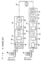
- FIG. 6 is a view showing the configuration of a conventional FM signal optical transmission system.
- the AM/FM converter 62 of a transmitter 61 directly modulates a semiconductor laser 41 by using multi-channel AM video signals and outputs an optical frequency-modulated signal.
- Optical amplitude modulation and oscillation frequency modulation are carried out simultaneously by directly modulating the semiconductor laser 41 by using AM signals 30.
- this optical signal is multiplexed with the light of a local oscillation light source 42 having an oscillation frequency slightly different from that of the optical signal, input to a photodiode 44, and optically heterodyne-detected, thereby obtaining an FM-modulated signal having a wideband (1 to 6 GH for example) as a beat signal for the two lasers.
- An electric/optic converter 63 directly modulates a transmission semiconductor laser 69 by using a semiconductor laser drive amplifier 68 to convert the FM-modulated signal into an optical signal, and the optical signal is transmitted via an optical fiber 72 (Patent Publication No. 2700622 for example).
- the optical signal is amplified by an optical amplifier or the like, and transmitted to individual receivers via optical branching devices. Only one receiver 73 is shown here.
- an optic/electric converter 75 converts the optical signal into an electric signal by using a photo-detector 76, amplifies the electric signal by using a preamplifier 77, and then an FM demodulator 74 demodulates the electric signal into the original AM signals 31.
- This FM demodulator 74 is a delay-type demodulation circuit comprising high-speed logic ICs 51 and 53 (AND gates for example), a delay device 52 and a low-pass filter 54 via a limiter amplifier 50, and is capable of carrying out wideband demodulation.
- AM signals are converted directly into an electrical FM signal; however, if the modulation index at the FM demodulator is increased (the degree of modulation ⁇ 10%), distortion occurs at the FM modulator, and this distortion deteriorates the quality of the signal, whereby it is impossible to carry out satisfactory optical transmission.
- the demodulator also uses a plurality of expensive high-speed logic ICs; therefore, this causes a problem in practical utility when it is assumed to be used for subscriber systems.
- EP 0503 512 A2 describes an AM/FM-converter which includes a broadband VCO to produce an FM-modulated signal. A band is selected by a low-pass filter from said FM-modulated signal. This band is converted down to a frequency range compatible with transmitter and receiver components used in system.
- EP 0 461 937 A2 describes a multiplexer to produce a frequency multiplexed (FDM) signal and the conversion into an optical signal.
- the present invention is intended to provide an FM signal optical transmission system and an FM signal optical transmitter having a simple configuration, low distortion and excellent reception sensitivity, and also to provide a voltage controlled oscillator at low cost in order to attain the FM signal optical transmission system and the FM signal optical transmitter.
- the 1st invention of the present invention is an FM signal optical transmitter comprising a signal processor for outputting an FM signal having a band including a fundamental oscillation frequency and plural higher-order harmonic components of said fundamental oscillation frequency, a band-pass filter for taking out only the predetermined-order harmonic signal component from said FM signal output from said signal processor, a frequency converter for shifting the taken-out harmonic signal component to the lower frequency side or the higher frequency side, and an electric/optic converter for converting the output signal of said frequency converter into an optical signal.
- the 2nd invention of the present invention is an FM signal optical transmitter comprising a signal processor for outputting an FM signal having a band including a fundamental oscillation frequency and plural higher-order harmonic components of said fundamental oscillation frequency, a band-pass filter for taking out only the predetermined-order harmonic signal component from said FM signal output from said signal processor, a frequency multiplier that directly multiplies the taken-out harmonic signal component or shifts said harmonic signal component to the lower frequency side or the higher frequency side and then multiplies the shifted signal, and an electric/optic converter that directly converts the frequency-multiplied signal into an optical signal or shifts said frequency-multiplied signal to the lower frequency side or the higher frequency side and then converts the shifted signal into an optical signal, wherein the modulation degree of said frequency-multiplied signal is raised to a predetermined modulation degree at the time of multiplication.
- the application also relates to an FM signal optical transmitter in accordance with said 1st or 2nd inventions, (corresponding to claim 3) wherein said signal processor for outputting said FM signal is a voltage controlled oscillator in accordance with said 1st or 2nd inventions, and said modulated voltage is formed of plural subcarrier-multiplexed signals.
- the application concerns an FM signal optical transmitter in accordance with said 1st invention, (corresponding to claim 4) wherein a predetermined harmonic carrier wave component is extracted from some harmonic components at the output of said signal processor, and the extracted harmonic carrier wave component is used as a reference frequency source required when frequency conversion is carried by said frequency converter.
- the application also concerns (an FM signal optical transmitter in accordance with said 2nd invention,) (corresponding to claim 4) wherein said frequency shifting is carried out by a frequency converter, a predetermined harmonic carrier wave component is extracted from some harmonic components at the output of said signal processor, and the extracted harmonic carrier wave component is used as a reference frequency source required when frequency conversion is carried by said frequency converter.
- the application also relates to an FM signal optical transmission system comprising said FM signal optical transmitter in accordance with any one of claims 1 to 4 (corresponding to claim 5) and further comprising an optic/electric converter that receives an optical signal transmitted from said FM signal optical transmitter and converts said optical signal into an electric signal, and an FM demodulator for demodulating an FM signal converted into said electric signal.
- an FM modulator is used to convert AM signals into an FM signal and comprises a voltage controlled oscillator and a phase modulator.
- the FM signal may be synthesized indirectly from the AM signals or phase-modulated signals instead of direct conversion into the FM signal.
- a semiconductor laser is used as an electric/optic converter.
- an ordinary optical fiber is used as an optical fiber.
- an ordinary fiber having a core diameter of about 10 to 300 ⁇ m is available for example. Both multi-mode and single-mode optical fibers can be used.
- a frequency converter converts a frequency to a higher-frequency side or a lower-frequency side by using the frequency mixing action of a non-linear circuit device, just like a frequency multiplier.
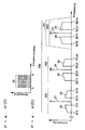
- FIG. 1 is a view showing the configuration of an FM signal optical transmission system in accordance with a first embodiment of the present invention.
- the present optical transmission system comprises a transmitter 1 and a receiver 13.
- the transmitter 1 is provided with an FM converter 2 comprising a voltage controlled oscillator 4, a band-pass filter 5 and a frequency converter 7, and an electric/optic converter 3 comprising a wideband amplifier 8 and a semiconductor laser 9.
- the receiver 13 is provided with an optic/electric converter 15 comprising a photo-detector (PD) 16 and a preamplifier 17, and an FM demodulator 14 comprising a limiter amplifier 50, a branching device 51, a delay circuit 52, a mixer 53 and a low-pass filter 54.
- An optical signal from the transmitter 1 is transmitted via an optical fiber 12 and input to the receiver 13.
- the transmitter 1 corresponds to the FM signal optical transmitter of the present invention. This also applies to the following embodiments in the same way.
- FIG. 2 is a conceptual view showing signal spectra and illustrating the operation of the optical transmission system in accordance with the present embodiment.
- the above-mentioned voltage controlled oscillator 4 may be an oscillator comprising a varactor or a reactance transistor, or a digital oscillator comprising a multivibrator.
- AM signals 20, i.e., multi-channel, subcarrier-multiplexed video signals, as shown in FIG. 2 (a) are converted into an FM-converted signal 200 shown in FIG. 2 (b) by this voltage controlled oscillator 4.
- This FM-converted signal 200 is obtained when an FM signal 201 for each channel of the multi-channel, subcarrier-multiplexed video signals, centered at the fundamental carrier frequency f0 of the voltage controlled oscillator 4, undergoes narrow-band FM modulation having a low degree of modulation to the extent that sidebands other than first sidebands 22 and 23 do not appear significantly. Therefore, as shown in FIG.
- the first sidebands 22 and 23 of the fundamental carrier wave component appear at regions each being f1 away from the FM carrier wave 21 (frequency f0), and at the same time the harmonic spectra 202 and 203 (frequencies 2f0, 3f0, ...) of the fundamental carrier wave are also output simultaneously.
- nth-order harmonic component an integer (n ⁇ 2), for example
- n an integer (n ⁇ 2), for example
- output from the output stage of the voltage controlled oscillator 4 and selected by the band-pass filter 5 has a fundamental oscillation frequency and an input fluctuation voltage level not overlapping the (n - 1)th-order and (n + 1)th-order harmonic components on the frequency axis each other
- This FM signal 200 is input to the band-pass filter 5 having a frequency selection characteristic 251 centered at the third harmonic frequency 3f0 shown in FIG. 2 (b), and this third harmonic spectrum 203 is selected and taken out as an output.
- a band-pass filter for passing the third harmonic is taken as an example of the band-pass filter 5; however, the order of the harmonic to be selected is not limited to this; any order may be selected depending on the output level and a desired degree of modulation of the harmonic from the voltage controlled oscillator 4.
- This third-order harmonic spectrum 203 has a degree of modulation three times as high as that of the FM signal 201.
- This third-order harmonic signal is down-converted by the frequency converter 7 such as a mixer to the lower-frequency side, i.e., into a band wherein optical transmission is possible.
- This FM signal having an increased degree of modulation is converted into an optical signal by the semiconductor laser 9 via the wideband amplifier 8, input to the optical fiber 12, and transmitted.
- the optical signal transmitted by the optical fiber 12 is input to the receiver 13.
- the optical signal input to the receiver 13 is converted into an electric signal by the optic/electric converter 15 provided with the photo-detector 16 formed of a photo-detecting device, such as a photodiode or an avalanche photodiode, and the preamplifier 17, amplified to have a desired signal intensity, and demodulated into the original AM signals 31 by the FM demodulator 14.
- the FM demodulator 14 can have one of several configurations, a delay line type having excellent linearity in a wideband or a pulse count type is desirable.
- the delay line type is described, which comprises the branching device 51, the mixer 53 and the delay circuit 52.
- the mixer 53 may be formed of a wideband balance-type mixer. Furthermore, as shown in FIG.
- the limiter amplifier 50 for level adjustment may be connected at the front stage of the branching device 51, and the low-pass filter 54 may be connected at the rear stage of the mixer 53 as necessary in the FM demodulator 14.
- the FM demodulator 14 is not limited to the above-mentioned configuration but may be formed of a circuit having a frequency discrimination function, such as a double-tuning frequency discriminator, a Foster-Seeley discriminator, a ratio detector or the like.
- Either the upper sideband or the lower sideband of the FM signal converted by the transmitter 1 may be transmitted.
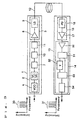
- FIG. 3 is a view showing the configurations of the transmitter 1 and the receiver 13 of an FM signal optical transmission system in accordance with a second embodiment of the present invention.
- This embodiment differs from the first embodiment shown in FIG. 1 in that a frequency multiplier 10 and a frequency converter 11 are provided after a frequency converter 7.
- the components represented in the figure by the same numerals are the same as those shown in FIG. 1.
- the receiver 13 is the same as that of the first embodiment, and its explanation is omitted.
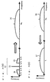
- an FM-converted signal 61 including a carrier wave (herein, f0 for convenience) is N-multiplied (N: integer) by the frequency multiplier 10 as shown in FIG. 4 (a), whereby a multiplied signal 36 is obtained and the FM modulation degree is increased and the desired modulation degree can be obtained; next, the N-multiplied signal 36 is shifted by the frequency converter 11 to the lower frequency side as shown in FIG. 4 (b), whereby an FM signal 37 having an optical transmittable band can be obtained.
- a band-pass filter may be inserted as necessary at the rear stage of the frequency multiplier 10 or the frequency converter 11 to carry out spurious suppression.
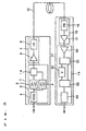
- FIG. 5 is a view showing the configuration of an FM signal optical transmission system in accordance with a third embodiment of the present invention.
- This embodiment differs from the first embodiment (FIG. 1) of the present invention in that a band-pass filter 6 is provided at the output of the voltage controlled oscillator 4 in parallel with the band-pass filter 5, whereby a branched signal from the voltage controlled oscillator 4 is input to the band-pass filter 6, and its output signal is input to a frequency converter 18.
- the band-pass filter 6 has a narrow-band-pass characteristic of selecting only the harmonic frequency portion of the fundamental carrier frequency f0 in the FM signal 200 (see FIG. 2) from the voltage controlled oscillator 4.
- the band-pass filter 6 selects a second-order harmonic spectrum 202 not including sideband components 25 and 26. This second-order harmonic spectrum 202 is used as the local oscillation source of the frequency converter 18.
- the band-pass filter 6 used to select the second-order harmonic is taken as an example; however, without being limited to this, it may be possible to have a characteristic wherein a higher-order harmonic around the local oscillation frequency required for carrying out shifting to the optical transmission band is selected.
- the present invention typically relates to an FM signal optical transmitter for converting multi-channel AM signals into an FM signal, and also relates to an FM signal optical transmission system including the FM signal optical transmitter, wherein plural subcarrier-multiplexed signals are narrow-band-FM-modulated by a voltage controlled oscillator including the fundamental carrier wave and higher-order harmonics as the output, and the FM carrier wave component of the higher-order harmonics of the fundamental carrier wave is selectively taken out by a band-rejection filter, shifted to the lower frequency side by a frequency converter, converted into an optical signal and transmitted.
- the subcarrier-multiplexed signals of the present invention are not limited to AM signals; the signals may be any given modulated signals, such as phase-modulated, FM-modulated or digitally modulated signals.
- the shifting is carried out to the lower frequency side before multiplication in the above-mentioned embodiment; however, if optical processing is possible, the shifting may be carried out to the higher frequency side. Alternatively, if optical processing is possible, the shifting may not be carried out.
- the shifting is carried out to the lower frequency side after multiplication, if optical processing is possible, the shifting may be carried out to the higher frequency side. Alternatively, if optical processing is possible, the shifting may not be carried out.
- plural subcarrier-multiplexed signals are narrow-band-FM-modulated by a voltage controlled oscillator including the fundamental carrier wave and higher-order harmonics as the output, and the FM carrier wave component of the higher-order harmonics of the fundamental carrier wave is selectively taken out by a band-rejection filter, shifted to the lower frequency side by a frequency converter, converted into an optical signal and transmitted, whereby an FM signal capable of being transmitted via an optical fiber can be generated by using a simple configuration, thereby having the advantages of excellent stability and reliability and low cost.
Landscapes
- Physics & Mathematics (AREA)
- Electromagnetism (AREA)
- Engineering & Computer Science (AREA)
- Computer Networks & Wireless Communication (AREA)
- Signal Processing (AREA)
- Power Engineering (AREA)
- Optics & Photonics (AREA)
- Optical Communication System (AREA)
Claims (5)
- Optischer FM-Signal-Sender (1), der umfasst:gekennzeichnet dadurch, dass das Bandpassfilter (5) nur eine harmonische Signalkomponente (203) vorgegebener Ordnung aus dem von der Signalverarbeitungseinrichtung ausgegebenen FM-Signal entfernt,eine Signalverarbeitungseinrichtung, die ein FM-Signal ausgibt, das ein Band (200) hat, das eine Grundschwingungsfrequenz (21) und mehrere harmonische Komponenten (24, 27) höherer Ordnung der Grundschwingungsfrequenz einschließt, undein Bandpassfilter (5),
durch einen Frequenzwandler (7), der die entfernte harmonische Signalkomponente zur niederfrequenten Seite oder höherfrequenten Seite verschiebt, und
einen elektrooptischen Wandler (3), der das Ausgangssignal des Frequenzwandlers in ein optisches Signal umwandelt. - Optischer FM-Signal-Sender (1), der umfasst:gekennzeichnet dadurch, dass das Bandpassfilter (5) nur eine harmonische Signalkomponente (61) vorgegebener Ordnung aus dem von der Signalverarbeitungseinrichtung ausgegebenen FM-Signal entfernt,eine Signalverarbeitungseinrichtung, die ein FM-Signal ausgibt, das ein Band (200) hat, das eine Grundschwingungsfrequenz (21) und mehrere harmonische Komponenten (24, 27) höherer Ordnung der Grundschwingungsfrequenz einschließt, undein Bandpassfilter (5),
durch einen Frequenzvervielfacher (10), der die entfernte harmonische Signalkomponente (61) direkt vervielfacht oder die harmonische Signalkomponente (61) zur niederfrequenten Seite oder zur höherfrequenten Seite verschiebt und das verschobene Signal (36) dann vervielfacht, und
einen elektrooptischen Wandler, der das frequenzvervielfachte Signal direkt in ein optisches Signal umwandelt oder das frequenzvervielfachte Signal (36) zur niederfrequenten Seite oder höherfrequenten Seite verschiebt und das verschobene Signal dann in ein optisches Signal umwandelt, wobei der Modulationsgrad des frequenzvervielfachten Signals (36) bei der Vervielfachung auf einen vorgegebenen Modulationsgrad erhöht wird. - Optischer FM-Signal-Sender (1) nach Anspruch 1 oder 2, wobei die Signalverarbeitungseinrichtung zum Ausgeben des FM-Signals ein spannungsgesteuerter Oszillator ist.
- Optischer FM-Signal-Sender (1) nach einem der Ansprüche 1-3, wobei eine vorgegebene harmonische Trägerwellenkomponente (z. B. 27) aus den harmonischen Komponenten am Ausgang der Signalverarbeitungseinrichtung extrahiert wird, und
die extrahierte harmonische Trägerwellenkomponente (z. B. 27) als eine Bezugsfrequenzquelle verwendet wird, die erforderlich ist, wenn Frequenzwandlung durch den Frequenzwandler (18) ausgeführt wird. - Optisches FM-Signal-Sendesystem, das umfasst:einen optischen FM-Signal-Sender (1) nach einem der Ansprüche 1 bis 4, einen optoelektrischen Wandler (15), der ein optisches Signal empfängt, das von dem optischen FM-Signal-Sender (1) gesendet wird, und das optische Signal in ein elektrisches Signal umwandelt, sowie einen FM-Demodulator (14), der ein in das elektrische Signal (31) umgewandeltes FM-Signal demoduliert.
Priority Applications (1)
| Application Number | Priority Date | Filing Date | Title |
|---|---|---|---|
| EP05000949A EP1524784A3 (de) | 1999-03-31 | 2000-03-23 | Spannungsgesteuerter Oszillator |
Applications Claiming Priority (2)
| Application Number | Priority Date | Filing Date | Title |
|---|---|---|---|
| JP9333499 | 1999-03-31 | ||
| JP9333499 | 1999-03-31 |
Related Child Applications (1)
| Application Number | Title | Priority Date | Filing Date |
|---|---|---|---|
| EP05000949A Division EP1524784A3 (de) | 1999-03-31 | 2000-03-23 | Spannungsgesteuerter Oszillator |
Publications (2)
| Publication Number | Publication Date |
|---|---|
| EP1041749A1 EP1041749A1 (de) | 2000-10-04 |
| EP1041749B1 true EP1041749B1 (de) | 2005-10-26 |
Family
ID=14079382
Family Applications (2)
| Application Number | Title | Priority Date | Filing Date |
|---|---|---|---|
| EP05000949A Withdrawn EP1524784A3 (de) | 1999-03-31 | 2000-03-23 | Spannungsgesteuerter Oszillator |
| EP00106313A Expired - Lifetime EP1041749B1 (de) | 1999-03-31 | 2000-03-23 | Optisches FM Übertragungssystem |
Family Applications Before (1)
| Application Number | Title | Priority Date | Filing Date |
|---|---|---|---|
| EP05000949A Withdrawn EP1524784A3 (de) | 1999-03-31 | 2000-03-23 | Spannungsgesteuerter Oszillator |
Country Status (3)
| Country | Link |
|---|---|
| US (2) | US6658216B1 (de) |
| EP (2) | EP1524784A3 (de) |
| DE (1) | DE60023386T2 (de) |
Families Citing this family (9)
| Publication number | Priority date | Publication date | Assignee | Title |
|---|---|---|---|---|
| US6658216B1 (en) * | 1999-03-31 | 2003-12-02 | Matsushita Electric Industrial Co., Ltd. | Voltage controlled oscillator, FM signal optical transmitter, FM signal optical receiver and FM signal optical transmission system |
| US7346279B1 (en) * | 2002-03-25 | 2008-03-18 | Forster Energy Llc | Optical transceiver using heterodyne detection and a transmitted reference clock |
| WO2005006600A1 (ja) * | 2003-07-11 | 2005-01-20 | Nippon Telegraph And Telephone Corporation | 光信号送信機及び光信号伝送システム |
| US7554324B2 (en) * | 2003-10-28 | 2009-06-30 | Honeywell International Inc. | Turbine blade proximity sensor and control system |
| JP2005277713A (ja) * | 2004-03-24 | 2005-10-06 | Toshiba Corp | 光伝送システムとその光送信装置 |
| JP5098569B2 (ja) * | 2007-10-25 | 2012-12-12 | ヤマハ株式会社 | 帯域拡張再生装置 |
| JP5870754B2 (ja) * | 2012-02-27 | 2016-03-01 | 富士通株式会社 | 光信号送信装置及び光信号送信方法 |
| RU2628121C1 (ru) * | 2016-10-11 | 2017-08-15 | Компания АМОТЕК ТЕКНОЛОДЖИ ОЮ, рег. N 14113251 | Способ построения широкодиапазонного преобразователя частоты радиосигналов и устройство для его осуществления |
| JP7541254B2 (ja) * | 2020-12-28 | 2024-08-28 | 日本電信電話株式会社 | 光送信装置及び信号検出方法 |
Family Cites Families (12)
| Publication number | Priority date | Publication date | Assignee | Title |
|---|---|---|---|---|
| US3469214A (en) * | 1966-08-26 | 1969-09-23 | Matsushita Electric Industrial Co Ltd | Reactance transistor circuit configuration |
| JPH0448889A (ja) | 1990-06-15 | 1992-02-18 | Nec Corp | 光catv分配方式 |
| US5128755B1 (en) * | 1990-07-25 | 1999-03-23 | Wireless Technology Inc | Wireless real time video system and method of making the same |
| US5212579A (en) | 1991-03-11 | 1993-05-18 | General Instrument Corporation | Method and apparatus for communicating amplitude modulated signals over an optical communication path |
| GB9510127D0 (en) * | 1995-05-20 | 1995-08-02 | West End System Corp | CATV Data transmission system |
| US6016426A (en) * | 1996-10-10 | 2000-01-18 | Mvs, Incorporated | Method and system for cellular communication with centralized control and signal processing |
| US5903196A (en) * | 1997-04-07 | 1999-05-11 | Motorola, Inc. | Self centering frequency multiplier |
| JPH1141171A (ja) | 1997-07-18 | 1999-02-12 | Hitachi Cable Ltd | 光伝送システム |
| US6268777B1 (en) * | 1997-11-20 | 2001-07-31 | Applied Micro Circuits Corporation | Single inductor fully integrated differential voltage controlled oscillator with automatic amplitude adjustment and on-chip varactor |
| EP0932268B1 (de) * | 1998-01-27 | 2006-08-16 | Matsushita Electric Industrial Co., Ltd. | Optischer FM-Signal-Sender |
| US6091940A (en) * | 1998-10-21 | 2000-07-18 | Parkervision, Inc. | Method and system for frequency up-conversion |
| US6658216B1 (en) * | 1999-03-31 | 2003-12-02 | Matsushita Electric Industrial Co., Ltd. | Voltage controlled oscillator, FM signal optical transmitter, FM signal optical receiver and FM signal optical transmission system |
-
2000
- 2000-03-20 US US09/531,341 patent/US6658216B1/en not_active Expired - Fee Related
- 2000-03-23 DE DE60023386T patent/DE60023386T2/de not_active Expired - Fee Related
- 2000-03-23 EP EP05000949A patent/EP1524784A3/de not_active Withdrawn
- 2000-03-23 EP EP00106313A patent/EP1041749B1/de not_active Expired - Lifetime
-
2003
- 2003-08-19 US US10/642,669 patent/US20040037571A1/en not_active Abandoned
Also Published As
| Publication number | Publication date |
|---|---|
| US20040037571A1 (en) | 2004-02-26 |
| US6658216B1 (en) | 2003-12-02 |
| EP1524784A2 (de) | 2005-04-20 |
| DE60023386T2 (de) | 2006-04-27 |
| DE60023386D1 (de) | 2005-12-01 |
| EP1041749A1 (de) | 2000-10-04 |
| EP1524784A3 (de) | 2005-06-15 |
Similar Documents
| Publication | Publication Date | Title |
|---|---|---|
| US7869668B2 (en) | Method for generating carrier residual signal and its device | |
| US6556327B1 (en) | Signal converter, optical transmitter and optical fiber transmission system | |
| US20030002120A1 (en) | System and method for generating analog transmission signals | |
| US7650084B2 (en) | Optical heterodyne receiver and method of extracting data from a phase-modulated input optical signal | |
| JP4332616B2 (ja) | 変調された光の信号処理方法およびその装置 | |
| JP3072259B2 (ja) | 低バイアス・ヘテロダイン光ファイバ通信リンク | |
| US6643470B1 (en) | FM signal converter, FM signal optical transmitter and FM signal optical receiver | |
| US6731922B1 (en) | Optical image reject down converter | |
| EP1041749B1 (de) | Optisches FM Übertragungssystem | |
| JP3467507B2 (ja) | 光搬送波を用いた高周波信号伝送方法および高周波信号伝送装置 | |
| JPH02162330A (ja) | 偏波ダイバシティ光受信方法とその装置および中間周波数安定化方法 | |
| US20020075539A1 (en) | Wavelength division multiplex optical transmitter, wavelength division multiplex optical receiver, optical transmission device, and optical transmission system and method | |
| US5923458A (en) | Frequency modulator | |
| US6452706B1 (en) | FM signal optical transmission apparatus and FM signal optical reception apparatus | |
| JP2007506318A (ja) | 光位相ロックドループ用の光電圧制御発振器 | |
| US5973820A (en) | FM modulation device | |
| JP2000349560A (ja) | 電圧制御発振器、fm信号光送信器、fm信号光受信器及びfm信号光伝送システム | |
| US7653318B2 (en) | Photonic phase locked loop detector/discriminator | |
| JP3863463B2 (ja) | 信号伝送方法および信号伝送システム | |
| US20080002984A1 (en) | Optical Transmission System Using Ossb-Modulation and Signal Trasmission Method Thereof | |
| US5134721A (en) | Noise eliminating device for angle-modulated wave | |
| US6594056B1 (en) | Receiver for use in a transmission system for spectral-coded data as well as a method | |
| JP2006287410A (ja) | 光送信装置、光受信装置及び光伝送システム | |
| JP3782599B2 (ja) | Fm信号光伝送装置 | |
| JP3168735B2 (ja) | コヒーレント光伝送装置 |
Legal Events
| Date | Code | Title | Description |
|---|---|---|---|
| PUAI | Public reference made under article 153(3) epc to a published international application that has entered the european phase |
Free format text: ORIGINAL CODE: 0009012 |
|
| 17P | Request for examination filed |
Effective date: 20000808 |
|
| AK | Designated contracting states |
Kind code of ref document: A1 Designated state(s): DE FR GB |
|
| AX | Request for extension of the european patent |
Free format text: AL;LT;LV;MK;RO;SI |
|
| AKX | Designation fees paid |
Free format text: DE FR GB |
|
| 17Q | First examination report despatched |
Effective date: 20040716 |
|
| GRAP | Despatch of communication of intention to grant a patent |
Free format text: ORIGINAL CODE: EPIDOSNIGR1 |
|
| RTI1 | Title (correction) |
Free format text: FM OPTICAL TRANSMISSION SYSTEM |
|
| RIN1 | Information on inventor provided before grant (corrected) |
Inventor name: IIDA, MASANORI Inventor name: ASAKURA, HIROYUKI Inventor name: ADACHI, HISASHI |
|
| GRAS | Grant fee paid |
Free format text: ORIGINAL CODE: EPIDOSNIGR3 |
|
| GRAA | (expected) grant |
Free format text: ORIGINAL CODE: 0009210 |
|
| AK | Designated contracting states |
Kind code of ref document: B1 Designated state(s): DE FR GB |
|
| REG | Reference to a national code |
Ref country code: GB Ref legal event code: FG4D |
|
| REF | Corresponds to: |
Ref document number: 60023386 Country of ref document: DE Date of ref document: 20051201 Kind code of ref document: P |
|
| ET | Fr: translation filed | ||
| PLBE | No opposition filed within time limit |
Free format text: ORIGINAL CODE: 0009261 |
|
| STAA | Information on the status of an ep patent application or granted ep patent |
Free format text: STATUS: NO OPPOSITION FILED WITHIN TIME LIMIT |
|
| 26N | No opposition filed |
Effective date: 20060727 |
|
| PGFP | Annual fee paid to national office [announced via postgrant information from national office to epo] |
Ref country code: DE Payment date: 20070315 Year of fee payment: 8 |
|
| PGFP | Annual fee paid to national office [announced via postgrant information from national office to epo] |
Ref country code: GB Payment date: 20070321 Year of fee payment: 8 |
|
| PGFP | Annual fee paid to national office [announced via postgrant information from national office to epo] |
Ref country code: FR Payment date: 20070308 Year of fee payment: 8 |
|
| GBPC | Gb: european patent ceased through non-payment of renewal fee |
Effective date: 20080323 |
|
| REG | Reference to a national code |
Ref country code: FR Ref legal event code: ST Effective date: 20081125 |
|
| PG25 | Lapsed in a contracting state [announced via postgrant information from national office to epo] |
Ref country code: DE Free format text: LAPSE BECAUSE OF NON-PAYMENT OF DUE FEES Effective date: 20081001 |
|
| PG25 | Lapsed in a contracting state [announced via postgrant information from national office to epo] |
Ref country code: FR Free format text: LAPSE BECAUSE OF NON-PAYMENT OF DUE FEES Effective date: 20080331 |
|
| PG25 | Lapsed in a contracting state [announced via postgrant information from national office to epo] |
Ref country code: GB Free format text: LAPSE BECAUSE OF NON-PAYMENT OF DUE FEES Effective date: 20080323 |