EP1041363B1 - Verfahren und Vorrichtung zum Anbringen eines Massstabes - Google Patents
Verfahren und Vorrichtung zum Anbringen eines Massstabes Download PDFInfo
- Publication number
- EP1041363B1 EP1041363B1 EP00105635A EP00105635A EP1041363B1 EP 1041363 B1 EP1041363 B1 EP 1041363B1 EP 00105635 A EP00105635 A EP 00105635A EP 00105635 A EP00105635 A EP 00105635A EP 1041363 B1 EP1041363 B1 EP 1041363B1
- Authority
- EP
- European Patent Office
- Prior art keywords
- scale
- mounting surface
- carrier
- scale carrier
- spacer
- Prior art date
- Legal status (The legal status is an assumption and is not a legal conclusion. Google has not performed a legal analysis and makes no representation as to the accuracy of the status listed.)
- Expired - Lifetime
Links
- 238000000034 method Methods 0.000 title claims abstract description 11
- 239000000758 substrate Substances 0.000 title 1
- 125000006850 spacer group Chemical group 0.000 claims abstract description 38
- 239000000853 adhesive Substances 0.000 claims abstract description 10
- 230000001070 adhesive effect Effects 0.000 claims abstract description 10
- 239000012790 adhesive layer Substances 0.000 claims description 8
- 238000004026 adhesive bonding Methods 0.000 claims description 2
- 238000006073 displacement reaction Methods 0.000 claims 1
- 239000011888 foil Substances 0.000 claims 1
- 239000002313 adhesive film Substances 0.000 description 5
- 238000003825 pressing Methods 0.000 description 3
- 241000668842 Lepidosaphes gloverii Species 0.000 description 2
- 229910000831 Steel Inorganic materials 0.000 description 2
- 239000002390 adhesive tape Substances 0.000 description 2
- 239000000969 carrier Substances 0.000 description 2
- 230000005484 gravity Effects 0.000 description 2
- 239000010959 steel Substances 0.000 description 2
- 241000446313 Lamella Species 0.000 description 1
- 229910052782 aluminium Inorganic materials 0.000 description 1
- XAGFODPZIPBFFR-UHFFFAOYSA-N aluminium Chemical compound [Al] XAGFODPZIPBFFR-UHFFFAOYSA-N 0.000 description 1
- 230000008878 coupling Effects 0.000 description 1
- 238000010168 coupling process Methods 0.000 description 1
- 238000005859 coupling reaction Methods 0.000 description 1
- 230000001419 dependent effect Effects 0.000 description 1
- 230000000694 effects Effects 0.000 description 1
- 239000011521 glass Substances 0.000 description 1
- 238000013507 mapping Methods 0.000 description 1
- 238000005259 measurement Methods 0.000 description 1
- 229910052751 metal Inorganic materials 0.000 description 1
- 239000002184 metal Substances 0.000 description 1
- 210000002023 somite Anatomy 0.000 description 1
Images


Classifications
-
- G—PHYSICS
- G01—MEASURING; TESTING
- G01D—MEASURING NOT SPECIALLY ADAPTED FOR A SPECIFIC VARIABLE; ARRANGEMENTS FOR MEASURING TWO OR MORE VARIABLES NOT COVERED IN A SINGLE OTHER SUBCLASS; TARIFF METERING APPARATUS; MEASURING OR TESTING NOT OTHERWISE PROVIDED FOR
- G01D5/00—Mechanical means for transferring the output of a sensing member; Means for converting the output of a sensing member to another variable where the form or nature of the sensing member does not constrain the means for converting; Transducers not specially adapted for a specific variable
- G01D5/26—Mechanical means for transferring the output of a sensing member; Means for converting the output of a sensing member to another variable where the form or nature of the sensing member does not constrain the means for converting; Transducers not specially adapted for a specific variable characterised by optical transfer means, i.e. using infrared, visible, or ultraviolet light
- G01D5/32—Mechanical means for transferring the output of a sensing member; Means for converting the output of a sensing member to another variable where the form or nature of the sensing member does not constrain the means for converting; Transducers not specially adapted for a specific variable characterised by optical transfer means, i.e. using infrared, visible, or ultraviolet light with attenuation or whole or partial obturation of beams of light
- G01D5/34—Mechanical means for transferring the output of a sensing member; Means for converting the output of a sensing member to another variable where the form or nature of the sensing member does not constrain the means for converting; Transducers not specially adapted for a specific variable characterised by optical transfer means, i.e. using infrared, visible, or ultraviolet light with attenuation or whole or partial obturation of beams of light the beams of light being detected by photocells
- G01D5/347—Mechanical means for transferring the output of a sensing member; Means for converting the output of a sensing member to another variable where the form or nature of the sensing member does not constrain the means for converting; Transducers not specially adapted for a specific variable characterised by optical transfer means, i.e. using infrared, visible, or ultraviolet light with attenuation or whole or partial obturation of beams of light the beams of light being detected by photocells using displacement encoding scales
- G01D5/34707—Scales; Discs, e.g. fixation, fabrication, compensation
Definitions
- the invention relates to a method for attaching a scale or scale carrier according to the preamble of claim 1 and a device designed for this purpose according to the preamble of claim 6.
- the invention is therefore based on the object of specifying a method and a device, with the / relatively relatively intrinsically stable scales or mecanicbandraj can be easily adhered to a body glued.
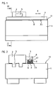
- FIGS. 1 and 2 show a coordinate measuring machine with a machine bed 1 and a carriage 2.
- the carriage 2 is displaceable in the longitudinal direction X along a linear guide 3.
- a length measuring device consisting of a scale 4 and a scanning head 5 is used.
- the scale 4 is a metal strip which is fastened in a form-fitting manner in a groove 6 of a scale carrier 7.
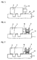
- the scale carrier 7 is provided on its underside 7.1 with a double-sided adhesive film 8.
- the adhesive film 8 with the adhesive layers 8.1 and 8.2 is shown enlarged in Figure 4.
- the scanning head 5 continuously scan the pitch 4.1 of the scale 4
- the scale carrier 7 must be aligned parallel to the direction of travel X of the scanning head 5 and thus the carriage 2 aligned.
- This alignment can only take place in a state in which the holding force of the adhesive 8.2 between the scale carrier 7 and the mounting surface 1.1 of the bed 1 is not yet effective, ie the adhesive 8.2 with this surface 1.1 still has no contact.
- this is placed on the acreage 1.1 by means of spacers 9.
- the spacers 9 have the function to keep the scale carrier 7 parallel spaced from the acreage 1.1 to move it easily defined on the cropping area 1.1 and thus to align.
- FIGS. 3 and 4 show a first mounting state of the scale carrier 7.
- the relatively self-stable scale carrier 7 is held at a plurality of spaced apart in the measuring direction X bodies by the spacers 9 at a distance to the cultivation area 1.1.
- the adhesive layer 8. 2 of the adhesive film 8 applied to the scale carrier 7 does not touch the mounting surface 1.1 at any point.
- the spacers 9 are in fact designed so that they embrace the scale carrier 7 laterally, so that it is held without play transverse to the measuring direction X and at a small distance to the cultivation area 1.1. Over the entire length of the scale carrier 7, the spacers 9 are distributed so that the deflection between two spacers 9 remains so low that the adhesive layer does not touch the cultivation area 8.1 1.1.
- the spacer 9 can hold the scale carrier 7 only by clamping or, as shown in Figure 4, alternatively or additionally, a pad 10 may be provided on the spacer 9, on which the scale carrier 7 with an adhesive-free area of its bottom 7.1 rests.
- the spacer 9 shown in Figure 4 is H-shaped.
- at least one of the legs of the spacer 9 is designed to be resiliently pivotable transversely to the measuring direction X.
- the right leg is pivotable about a joint 9.1, so that this leg of the spacer 9 can be spread for easy recording of the scale carrier 7.
- the spacers 9 may include magnets 17 to adhere slidably on magnetic mounting surfaces 1.1 ( Figure 4), or they may include connection options for vacuum hoses to adhere by means of vacuum on the mounting surface 1.1 slidably. Due to these possibilities, the scale carrier 7 can also be aligned on vertical cultivation surfaces or suspended.
- the scale carrier 7 can also be held magnetically or by vacuum on the spacers 9, wherein then in the aligned state, the magnetic force or the vacuum is deliberately reduced to cancel the coupling of spacer 9 and scale carrier 7 and the scale carrier 7 with the cultivation area 1.1 in contact and thus stick.
- the scale 4 can already be fastened during the alignment on the scale carrier 7, or can only be inserted into the groove 6 of the scale carrier 7 after the gluing.
- the described measures can also be used for aligning and mounting a scale 4 itself.
- the scale 4 can be a steel strip, a steel strip or a glass lamella.
- the adhesive film 8 may alternatively or additionally be provided on the mounting surface 1.1. Instead of the adhesive film 8, another adhesive layer can be provided continuously or interrupted.
Landscapes
- Physics & Mathematics (AREA)
- General Physics & Mathematics (AREA)
- Length-Measuring Instruments Using Mechanical Means (AREA)
- Length Measuring Devices With Unspecified Measuring Means (AREA)
- A Measuring Device Byusing Mechanical Method (AREA)
- Auxiliary Devices For And Details Of Packaging Control (AREA)
- Electrical Discharge Machining, Electrochemical Machining, And Combined Machining (AREA)
Applications Claiming Priority (2)
| Application Number | Priority Date | Filing Date | Title |
|---|---|---|---|
| DE19914311A DE19914311A1 (de) | 1999-03-29 | 1999-03-29 | Verfahren und Vorrichtung zum Anbringen eines Maßstabes |
| DE19914311 | 1999-03-29 |
Publications (3)
| Publication Number | Publication Date |
|---|---|
| EP1041363A2 EP1041363A2 (de) | 2000-10-04 |
| EP1041363A3 EP1041363A3 (de) | 2001-11-28 |
| EP1041363B1 true EP1041363B1 (de) | 2006-06-07 |
Family
ID=7902879
Family Applications (1)
| Application Number | Title | Priority Date | Filing Date |
|---|---|---|---|
| EP00105635A Expired - Lifetime EP1041363B1 (de) | 1999-03-29 | 2000-03-16 | Verfahren und Vorrichtung zum Anbringen eines Massstabes |
Country Status (6)
| Country | Link |
|---|---|
| US (1) | US6349481B1 (enExample) |
| EP (1) | EP1041363B1 (enExample) |
| JP (1) | JP4681708B2 (enExample) |
| AT (1) | ATE329233T1 (enExample) |
| DE (2) | DE19914311A1 (enExample) |
| ES (1) | ES2265819T3 (enExample) |
Families Citing this family (25)
| Publication number | Priority date | Publication date | Assignee | Title |
|---|---|---|---|---|
| DE10056947A1 (de) * | 2000-11-17 | 2002-05-23 | Optolab Licensing Gmbh | Verfahren und Anordnung zur Montage von Messsystemen |
| DE10059308A1 (de) * | 2000-11-29 | 2002-06-13 | Heidenhain Gmbh Dr Johannes | Verfahren zur Montage eines Längenmessgerät und entsprechendes Längenmessgerät |
| DE10204611B4 (de) | 2002-02-05 | 2007-04-05 | Dr. Johannes Heidenhain Gmbh | Verfahren und Vorrichtung zum Anbringen eines Maßstabes oder Maßstabträgers |
| US6612047B1 (en) * | 2002-02-19 | 2003-09-02 | Acu-Rite, Inc. | Length measuring device |
| DE10229888B4 (de) * | 2002-07-03 | 2010-09-30 | Dr. Johannes Heidenhain Gmbh | Vorrichtung und Verfahren zum Anbringen eines Maßstabs oder Maßstabträgers oder einer Maßstabführung sowie Maßstab, Maßstabträger oder Maßstabführung oder Schutzband dafür |
| DE10229885B4 (de) * | 2002-07-03 | 2010-06-24 | Dr. Johannes Heidenhain Gmbh | Verfahren und Vorrichtung zum Anbringen eines Maßstabs oder Maßstabträgers oder einer Maßstabführung |
| DE10236381A1 (de) | 2002-08-08 | 2004-02-19 | Dr. Johannes Heidenhain Gmbh | Längenmesseinrichtung |
| DE10243021A1 (de) * | 2002-09-17 | 2004-03-25 | Ina-Schaeffler Kg | Führungsschiene eines Linearwälzlagers |
| DE10249884B4 (de) * | 2002-10-25 | 2010-11-18 | Dr. Johannes Heidenhain Gmbh | Geschütztes Längenmeßsystem |
| DE10262008B4 (de) | 2002-10-25 | 2010-08-19 | Dr. Johannes Heidenhain Gmbh | Längenmeßsystem |
| US20040123684A1 (en) * | 2002-12-17 | 2004-07-01 | Excel Precision Corporation | Digital scale for linear or rotary stage |
| US20060174721A1 (en) * | 2002-12-17 | 2006-08-10 | Excel Precision Corporation | Digital scale for linear or rotary stage |
| JP4230810B2 (ja) * | 2003-04-24 | 2009-02-25 | 株式会社ミツトヨ | 測長装置 |
| DE10341297B3 (de) * | 2003-09-04 | 2005-07-07 | Dorma Gmbh + Co. Kg | Codierte Absolutpositions-Messung für in Schienen geführte Elemente |
| EP1621847B1 (de) | 2004-07-23 | 2013-07-17 | Dr. Johannes Heidenhain GmbH | Bauteil, insbesondere Sensor, und Verfahren zum Verkleben des Bauteils |
| EP1788360B1 (en) * | 2005-11-21 | 2008-07-30 | Fagor, S.Coop. | Readhead for a measuring device. |
| JP5108289B2 (ja) * | 2005-12-06 | 2012-12-26 | 株式会社ミツトヨ | 変位測定装置用スケール |
| DE102007031976A1 (de) * | 2007-07-10 | 2009-01-15 | Dr. Johannes Heidenhain Gmbh | Längenmesseinrichtung |
| DE102009044917A1 (de) * | 2009-09-23 | 2011-04-07 | Dr. Johannes Heidenhain Gmbh | Längenmesseinrichtung |
| DE102011120708B4 (de) | 2011-12-12 | 2018-10-04 | Novoferm Tormatic Gmbh | Verfahren zum Betrieb einer Antriebseinheit eines automatisierten Tores oder dergleichen |
| JP2015231882A (ja) * | 2014-06-09 | 2015-12-24 | 株式会社ミツトヨ | テープスケール接着治具及びテープスケール接着方法 |
| JP6712827B2 (ja) * | 2016-01-07 | 2020-06-24 | ハイデンハイン株式会社 | リニアエンコーダ |
| PT3248730T (pt) * | 2016-05-27 | 2021-09-15 | Univ Del Pais Vasco Euskal Herriko Unibertsitatea Upv/Ehu | Dispositivo e método para arrefecimento e lubrificação de ferramentas em processos de usinagem |
| ES2699201T3 (es) * | 2016-06-29 | 2019-02-07 | Heidenhain Gmbh Dr Johannes | Dispositivo de montaje y procedimiento para retraer una cinta en una ranura de un soporte de cinta métrica |
| EP3477263B1 (de) * | 2017-10-26 | 2019-12-11 | Dr. Johannes Heidenhain GmbH | Anordnung mit einem an einem träger befestigten massstab |
Family Cites Families (22)
| Publication number | Priority date | Publication date | Assignee | Title |
|---|---|---|---|---|
| DE2623526C2 (de) | 1976-05-26 | 1978-03-09 | Dr. Johannes Heidenhain Gmbh, 8225 Traunreut | Gekapselte Meßeinrichtung |
| DE2900113C2 (de) | 1979-01-03 | 1985-08-29 | Dr. Johannes Heidenhain Gmbh, 8225 Traunreut | Längenmeßeinrichtung mit längsverschieblichem Maßstab |
| DE3008384A1 (de) | 1980-03-05 | 1981-09-10 | Dr. Johannes Heidenhain Gmbh, 8225 Traunreut | Messeinrichtung |
| US4549353A (en) * | 1982-07-28 | 1985-10-29 | Mitutoyo Mfg. Co., Ltd. | Displacement measuring instrument |
| DE3302643C2 (de) | 1983-01-27 | 1987-01-08 | Dr. Johannes Heidenhain Gmbh, 8225 Traunreut | Spanneinrichtung für eine Längenmeßeinrichtung |
| DE3315214A1 (de) | 1983-04-27 | 1984-10-31 | Dr. Johannes Heidenhain Gmbh, 8225 Traunreut | Laengen- oder winkelmesseinrichtung |
| US4569137A (en) * | 1983-06-07 | 1986-02-11 | Mitutoyo Mfg. Co., Ltd. | Linear scale type displacement measuring device and main scale attaching method thereof |
| DE3503144C1 (de) | 1985-01-31 | 1985-11-28 | Dr. Johannes Heidenhain Gmbh, 8225 Traunreut | Freitragende Massverkoerperung |
| GB8820777D0 (en) | 1988-09-02 | 1988-10-05 | Renishaw Plc | Tape scale applicator |
| DE3918490C1 (enExample) | 1989-06-07 | 1990-09-27 | Dr. Johannes Heidenhain Gmbh, 8225 Traunreut, De | |
| JP2627193B2 (ja) * | 1989-07-21 | 1997-07-02 | ソニー・プレシジョン・テクノロジー株式会社 | スケール装置 |
| EP0506649B1 (de) * | 1991-03-25 | 1995-04-19 | RSF-Elektronik Gesellschaft m.b.H. | Längenmesssystem |
| JP2550316Y2 (ja) * | 1992-12-28 | 1997-10-08 | 株式会社東京精密 | 光学読取り式リニアスケール装置 |
| DE4406798C2 (de) | 1994-03-02 | 1997-11-27 | Heidenhain Gmbh Dr Johannes | Positionsmeßeinrichtung |
| DE4406799C2 (de) | 1994-03-02 | 1997-11-06 | Heidenhain Gmbh Dr Johannes | Positionsmeßeinrichtung |
| ATE161327T1 (de) * | 1994-05-06 | 1998-01-15 | Heidenhain Gmbh Dr Johannes | Temperatur-kompensierte positionsmesseinrichtung |
| DE19526517C2 (de) * | 1995-07-20 | 2000-08-24 | Zeiss Carl Jena Gmbh | Anordnung zur Befestigung einer Längenmeßeinrichtung |
| EP0836078B1 (de) | 1996-10-11 | 2002-12-18 | Dr. Johannes Heidenhain GmbH | Massstab einer Längenmesseinrichtung sowie Verfahren zur Anbringung eines Massstabs |
| ES2160294T3 (es) * | 1996-11-11 | 2001-11-01 | Heidenhain Gmbh Dr Johannes | Dispositivo de medicion de longitudes. |
| DE19700367C2 (de) * | 1997-01-08 | 1999-07-01 | Zeiss Carl Jena Gmbh | Verfahren und Montagevorrichtung zum gerichteten Anbringen eines Maßbandes |
| DE19724732A1 (de) * | 1997-06-12 | 1998-12-17 | Heidenhain Gmbh Dr Johannes | Längenmeßsystem mit modular aufgebautem Maßstab |
| DE19802036B4 (de) * | 1998-01-21 | 2006-11-30 | Dr. Johannes Heidenhain Gmbh | Verfahren und Vorrichtung zur mechanischen Justage von Teilungsträgern |
-
1999
- 1999-03-29 DE DE19914311A patent/DE19914311A1/de not_active Withdrawn
-
2000
- 2000-03-16 ES ES00105635T patent/ES2265819T3/es not_active Expired - Lifetime
- 2000-03-16 EP EP00105635A patent/EP1041363B1/de not_active Expired - Lifetime
- 2000-03-16 AT AT00105635T patent/ATE329233T1/de not_active IP Right Cessation
- 2000-03-16 DE DE50012879T patent/DE50012879D1/de not_active Expired - Lifetime
- 2000-03-28 JP JP2000089457A patent/JP4681708B2/ja not_active Expired - Fee Related
- 2000-03-29 US US09/537,625 patent/US6349481B1/en not_active Expired - Fee Related
Also Published As
| Publication number | Publication date |
|---|---|
| DE50012879D1 (de) | 2006-07-20 |
| EP1041363A2 (de) | 2000-10-04 |
| ATE329233T1 (de) | 2006-06-15 |
| ES2265819T3 (es) | 2007-03-01 |
| US6349481B1 (en) | 2002-02-26 |
| EP1041363A3 (de) | 2001-11-28 |
| JP4681708B2 (ja) | 2011-05-11 |
| JP2000292101A (ja) | 2000-10-20 |
| DE19914311A1 (de) | 2000-10-05 |
Similar Documents
| Publication | Publication Date | Title |
|---|---|---|
| EP1041363B1 (de) | Verfahren und Vorrichtung zum Anbringen eines Massstabes | |
| DE3623506C2 (enExample) | ||
| DE10229888B4 (de) | Vorrichtung und Verfahren zum Anbringen eines Maßstabs oder Maßstabträgers oder einer Maßstabführung sowie Maßstab, Maßstabträger oder Maßstabführung oder Schutzband dafür | |
| DE3813897C2 (enExample) | ||
| EP0169189B2 (de) | Lineares Messsystem | |
| EP0671606A2 (de) | Positionsmesseinrichtung | |
| DE3346583A1 (de) | Vorrichtung zum arbeiten auf bogenfoermigem material | |
| DE19700367C2 (de) | Verfahren und Montagevorrichtung zum gerichteten Anbringen eines Maßbandes | |
| EP0681159B1 (de) | Temperatur-kompensierte Positionsmesseinrichtung | |
| EP1390285B1 (de) | Einrichtung zum anbringen eines codebandes an einer tragstruktur eines aufzuges | |
| DE3340677C2 (de) | Zeichen- oder Graviereinrichtung | |
| DE3808443A1 (de) | Verfahren und vorrichtung zum ankleben von biegeschlaffen strangartigen profilen | |
| DE10229885B4 (de) | Verfahren und Vorrichtung zum Anbringen eines Maßstabs oder Maßstabträgers oder einer Maßstabführung | |
| EP0782697B1 (de) | Anordnung zur formschlüssigen aufnahme eines massstabs | |
| CH631337A5 (de) | Vorrichtung zum schutz der gonaden. | |
| DE102018133683A1 (de) | Gerät und Verfahren zum Positionieren von Materiallagen, insbesondere Fasern, auf einem Formwerkzeug | |
| DE19504929C2 (de) | Verfahren und Gerät zur Einmessung von Randfliesen beim Fliesenlegen | |
| DE102022106067B4 (de) | Klebevorrichtung und Verfahren zum Ankleben einer Rohrleitung auf einem plattenförmigen Bauteil | |
| DE102008044499B4 (de) | Anreißvorrichtung insbesondere für die Verlegung von Fertigparkett | |
| DE102016203509A1 (de) | Vorrichtung und Verfahren zum Anbringen einer Maßverkörperung | |
| DE102007033574A1 (de) | Längenmesseinrichtung | |
| EP0557782A1 (de) | Vorrichtung zum Auftragen von Kleber auf Bodenplatten | |
| DE3226415C2 (de) | Lehre zum Anpassen von Bauteilen wie z.B. Zier-, Kalk- und Verkleidungsleisten od.dgl. an unebene Wandoberflächen | |
| AT402631B (de) | Verfahren zum auftragen von klebeetiketten verfahren zum auftragen von klebeetiketten | |
| DE68906881T2 (de) | Bandmassanbringvorrichtung. |
Legal Events
| Date | Code | Title | Description |
|---|---|---|---|
| PUAI | Public reference made under article 153(3) epc to a published international application that has entered the european phase |
Free format text: ORIGINAL CODE: 0009012 |
|
| AK | Designated contracting states |
Kind code of ref document: A2 Designated state(s): AT BE CH CY DE DK ES FI FR GB GR IE IT LI LU MC NL PT SE |
|
| AX | Request for extension of the european patent |
Free format text: AL;LT;LV;MK;RO;SI |
|
| PUAL | Search report despatched |
Free format text: ORIGINAL CODE: 0009013 |
|
| AK | Designated contracting states |
Kind code of ref document: A3 Designated state(s): AT BE CH CY DE DK ES FI FR GB GR IE IT LI LU MC NL PT SE |
|
| AX | Request for extension of the european patent |
Free format text: AL;LT;LV;MK;RO;SI |
|
| 17P | Request for examination filed |
Effective date: 20020528 |
|
| AKX | Designation fees paid |
Free format text: AT BE CH CY DE DK ES FI FR GB GR IE IT LI LU MC NL PT SE |
|
| GRAP | Despatch of communication of intention to grant a patent |
Free format text: ORIGINAL CODE: EPIDOSNIGR1 |
|
| GRAS | Grant fee paid |
Free format text: ORIGINAL CODE: EPIDOSNIGR3 |
|
| GRAA | (expected) grant |
Free format text: ORIGINAL CODE: 0009210 |
|
| AK | Designated contracting states |
Kind code of ref document: B1 Designated state(s): AT BE CH CY DE DK ES FI FR GB GR IE IT LI LU MC NL PT SE |
|
| PG25 | Lapsed in a contracting state [announced via postgrant information from national office to epo] |
Ref country code: IT Free format text: LAPSE BECAUSE OF FAILURE TO SUBMIT A TRANSLATION OF THE DESCRIPTION OR TO PAY THE FEE WITHIN THE PRESCRIBED TIME-LIMIT;WARNING: LAPSES OF ITALIAN PATENTS WITH EFFECTIVE DATE BEFORE 2007 MAY HAVE OCCURRED AT ANY TIME BEFORE 2007. THE CORRECT EFFECTIVE DATE MAY BE DIFFERENT FROM THE ONE RECORDED. Effective date: 20060607 Ref country code: IE Free format text: LAPSE BECAUSE OF FAILURE TO SUBMIT A TRANSLATION OF THE DESCRIPTION OR TO PAY THE FEE WITHIN THE PRESCRIBED TIME-LIMIT Effective date: 20060607 Ref country code: FI Free format text: LAPSE BECAUSE OF FAILURE TO SUBMIT A TRANSLATION OF THE DESCRIPTION OR TO PAY THE FEE WITHIN THE PRESCRIBED TIME-LIMIT Effective date: 20060607 |
|
| REG | Reference to a national code |
Ref country code: GB Ref legal event code: FG4D Free format text: NOT ENGLISH |
|
| REG | Reference to a national code |
Ref country code: CH Ref legal event code: EP Ref country code: CH Ref legal event code: NV Representative=s name: TROESCH SCHEIDEGGER WERNER AG |
|
| GBT | Gb: translation of ep patent filed (gb section 77(6)(a)/1977) |
Effective date: 20060607 |
|
| REG | Reference to a national code |
Ref country code: IE Ref legal event code: FG4D Free format text: LANGUAGE OF EP DOCUMENT: GERMAN |
|
| REF | Corresponds to: |
Ref document number: 50012879 Country of ref document: DE Date of ref document: 20060720 Kind code of ref document: P |
|
| PG25 | Lapsed in a contracting state [announced via postgrant information from national office to epo] |
Ref country code: DK Free format text: LAPSE BECAUSE OF FAILURE TO SUBMIT A TRANSLATION OF THE DESCRIPTION OR TO PAY THE FEE WITHIN THE PRESCRIBED TIME-LIMIT Effective date: 20060907 Ref country code: SE Free format text: LAPSE BECAUSE OF FAILURE TO SUBMIT A TRANSLATION OF THE DESCRIPTION OR TO PAY THE FEE WITHIN THE PRESCRIBED TIME-LIMIT Effective date: 20060907 |
|
| PG25 | Lapsed in a contracting state [announced via postgrant information from national office to epo] |
Ref country code: PT Free format text: LAPSE BECAUSE OF FAILURE TO SUBMIT A TRANSLATION OF THE DESCRIPTION OR TO PAY THE FEE WITHIN THE PRESCRIBED TIME-LIMIT Effective date: 20061107 |
|
| REG | Reference to a national code |
Ref country code: ES Ref legal event code: FG2A Ref document number: 2265819 Country of ref document: ES Kind code of ref document: T3 |
|
| PLBE | No opposition filed within time limit |
Free format text: ORIGINAL CODE: 0009261 |
|
| STAA | Information on the status of an ep patent application or granted ep patent |
Free format text: STATUS: NO OPPOSITION FILED WITHIN TIME LIMIT |
|
| EN | Fr: translation not filed | ||
| 26N | No opposition filed |
Effective date: 20070308 |
|
| BERE | Be: lapsed |
Owner name: DR. JOHANNES HEIDENHAIN G.M.B.H. Effective date: 20070331 |
|
| PG25 | Lapsed in a contracting state [announced via postgrant information from national office to epo] |
Ref country code: BE Free format text: LAPSE BECAUSE OF NON-PAYMENT OF DUE FEES Effective date: 20070331 |
|
| PG25 | Lapsed in a contracting state [announced via postgrant information from national office to epo] |
Ref country code: MC Free format text: LAPSE BECAUSE OF NON-PAYMENT OF DUE FEES Effective date: 20070331 |
|
| PG25 | Lapsed in a contracting state [announced via postgrant information from national office to epo] |
Ref country code: GR Free format text: LAPSE BECAUSE OF FAILURE TO SUBMIT A TRANSLATION OF THE DESCRIPTION OR TO PAY THE FEE WITHIN THE PRESCRIBED TIME-LIMIT Effective date: 20060908 Ref country code: FR Free format text: LAPSE BECAUSE OF FAILURE TO SUBMIT A TRANSLATION OF THE DESCRIPTION OR TO PAY THE FEE WITHIN THE PRESCRIBED TIME-LIMIT Effective date: 20070309 |
|
| PG25 | Lapsed in a contracting state [announced via postgrant information from national office to epo] |
Ref country code: FR Free format text: LAPSE BECAUSE OF FAILURE TO SUBMIT A TRANSLATION OF THE DESCRIPTION OR TO PAY THE FEE WITHIN THE PRESCRIBED TIME-LIMIT Effective date: 20060607 |
|
| PG25 | Lapsed in a contracting state [announced via postgrant information from national office to epo] |
Ref country code: CY Free format text: LAPSE BECAUSE OF FAILURE TO SUBMIT A TRANSLATION OF THE DESCRIPTION OR TO PAY THE FEE WITHIN THE PRESCRIBED TIME-LIMIT Effective date: 20060607 Ref country code: LU Free format text: LAPSE BECAUSE OF NON-PAYMENT OF DUE FEES Effective date: 20070316 |
|
| PGFP | Annual fee paid to national office [announced via postgrant information from national office to epo] |
Ref country code: AT Payment date: 20100311 Year of fee payment: 11 |
|
| PGFP | Annual fee paid to national office [announced via postgrant information from national office to epo] |
Ref country code: NL Payment date: 20100315 Year of fee payment: 11 |
|
| REG | Reference to a national code |
Ref country code: NL Ref legal event code: V1 Effective date: 20111001 |
|
| PG25 | Lapsed in a contracting state [announced via postgrant information from national office to epo] |
Ref country code: AT Free format text: LAPSE BECAUSE OF NON-PAYMENT OF DUE FEES Effective date: 20110316 |
|
| PG25 | Lapsed in a contracting state [announced via postgrant information from national office to epo] |
Ref country code: NL Free format text: LAPSE BECAUSE OF NON-PAYMENT OF DUE FEES Effective date: 20111001 |
|
| PGFP | Annual fee paid to national office [announced via postgrant information from national office to epo] |
Ref country code: CH Payment date: 20150319 Year of fee payment: 16 Ref country code: ES Payment date: 20150326 Year of fee payment: 16 |
|
| PGFP | Annual fee paid to national office [announced via postgrant information from national office to epo] |
Ref country code: GB Payment date: 20150319 Year of fee payment: 16 |
|
| PGFP | Annual fee paid to national office [announced via postgrant information from national office to epo] |
Ref country code: DE Payment date: 20160321 Year of fee payment: 17 |
|
| REG | Reference to a national code |
Ref country code: CH Ref legal event code: PL |
|
| GBPC | Gb: european patent ceased through non-payment of renewal fee |
Effective date: 20160316 |
|
| PG25 | Lapsed in a contracting state [announced via postgrant information from national office to epo] |
Ref country code: GB Free format text: LAPSE BECAUSE OF NON-PAYMENT OF DUE FEES Effective date: 20160316 Ref country code: CH Free format text: LAPSE BECAUSE OF NON-PAYMENT OF DUE FEES Effective date: 20160331 Ref country code: LI Free format text: LAPSE BECAUSE OF NON-PAYMENT OF DUE FEES Effective date: 20160331 |
|
| REG | Reference to a national code |
Ref country code: ES Ref legal event code: FD2A Effective date: 20170428 |
|
| PG25 | Lapsed in a contracting state [announced via postgrant information from national office to epo] |
Ref country code: ES Free format text: LAPSE BECAUSE OF NON-PAYMENT OF DUE FEES Effective date: 20160317 |
|
| REG | Reference to a national code |
Ref country code: DE Ref legal event code: R119 Ref document number: 50012879 Country of ref document: DE |
|
| PG25 | Lapsed in a contracting state [announced via postgrant information from national office to epo] |
Ref country code: DE Free format text: LAPSE BECAUSE OF NON-PAYMENT OF DUE FEES Effective date: 20171003 |