EP0841540B1 - Längenmesseinrichtung - Google Patents
Längenmesseinrichtung Download PDFInfo
- Publication number
- EP0841540B1 EP0841540B1 EP97119509A EP97119509A EP0841540B1 EP 0841540 B1 EP0841540 B1 EP 0841540B1 EP 97119509 A EP97119509 A EP 97119509A EP 97119509 A EP97119509 A EP 97119509A EP 0841540 B1 EP0841540 B1 EP 0841540B1
- Authority
- EP
- European Patent Office
- Prior art keywords
- housing
- mounting block
- measuring device
- measuring direction
- length measuring
- Prior art date
- Legal status (The legal status is an assumption and is not a legal conclusion. Google has not performed a legal analysis and makes no representation as to the accuracy of the status listed.)
- Expired - Lifetime
Links
Images


Classifications
-
- G—PHYSICS
- G01—MEASURING; TESTING
- G01D—MEASURING NOT SPECIALLY ADAPTED FOR A SPECIFIC VARIABLE; ARRANGEMENTS FOR MEASURING TWO OR MORE VARIABLES NOT COVERED IN A SINGLE OTHER SUBCLASS; TARIFF METERING APPARATUS; MEASURING OR TESTING NOT OTHERWISE PROVIDED FOR
- G01D5/00—Mechanical means for transferring the output of a sensing member; Means for converting the output of a sensing member to another variable where the form or nature of the sensing member does not constrain the means for converting; Transducers not specially adapted for a specific variable
- G01D5/26—Mechanical means for transferring the output of a sensing member; Means for converting the output of a sensing member to another variable where the form or nature of the sensing member does not constrain the means for converting; Transducers not specially adapted for a specific variable characterised by optical transfer means, i.e. using infrared, visible, or ultraviolet light
- G01D5/32—Mechanical means for transferring the output of a sensing member; Means for converting the output of a sensing member to another variable where the form or nature of the sensing member does not constrain the means for converting; Transducers not specially adapted for a specific variable characterised by optical transfer means, i.e. using infrared, visible, or ultraviolet light with attenuation or whole or partial obturation of beams of light
- G01D5/34—Mechanical means for transferring the output of a sensing member; Means for converting the output of a sensing member to another variable where the form or nature of the sensing member does not constrain the means for converting; Transducers not specially adapted for a specific variable characterised by optical transfer means, i.e. using infrared, visible, or ultraviolet light with attenuation or whole or partial obturation of beams of light the beams of light being detected by photocells
- G01D5/347—Mechanical means for transferring the output of a sensing member; Means for converting the output of a sensing member to another variable where the form or nature of the sensing member does not constrain the means for converting; Transducers not specially adapted for a specific variable characterised by optical transfer means, i.e. using infrared, visible, or ultraviolet light with attenuation or whole or partial obturation of beams of light the beams of light being detected by photocells using displacement encoding scales
- G01D5/34707—Scales; Discs, e.g. fixation, fabrication, compensation
Definitions
- the invention relates to a length measuring device for measuring the relative position mutually movable objects according to the preamble of the claim 1 and a method for assembling a length measuring device according to the preamble of claim 15.
- Such a length measuring device - from which our invention is based - is described for example in DE 36 25 795 A1. That is the benchmark load-bearing housing is sealed on the two end faces using mounting blocks. Each of the mounting blocks is parallel on the front to the measuring direction aligned screws attached to the housing. The assembly blocks are rigidly attached to a machine bed with additional screws.
- the housing is made of a material whose coefficient of expansion differs from the machine bed. With changes in temperature leads therefore, the housing made a different length change than the machine bed between the two mounting blocks.
- These different changes in length cause a considerable tensile or compressive stress between the mounting block and the housing used by the front rope Screws must be included.
- the screws have to therefore be relatively strong, which has the consequence that relative to the housing lots of material to accommodate the bore and the screw thread must be provided.
- the size of the length measuring device is relative large.
- the document US 4 649 648 A shows a length measuring device with a housing, spherical projections are formed at the front ends thereof. These ledges are fitted into recesses in mounting blocks and are fastened with screws and a cover plate and the mounting blocks are on a machine part attached.
- EP 0 418 212 A2 there is another generic length measuring device described with mounting blocks arranged on the front.
- the mounting blocks are made in a continuous manner transverse to the measuring direction Bores inserted pins.
- the disadvantage here is that for the pens Fits must be provided and a removal after pinning the mounting blocks is difficult.
- a cover is provided which is attached to the housing by means of a holder connected is.
- the holder consists of an element with a measuring direction running threaded hole and is in a cross to the measuring direction leading milled in the housing.
- the lid placed on the face and a screw through a hole in the lid inserted at the front.
- the screw engages in the threaded hole of the element in and by tightening the screw, the lid is attached to the case drawn.
- the housing is attached to the machine bed by fastening elements arranged independently of the cover, which in Interact in the form of sliding guides with the housing. Between Slideways and the housing is only one when viewed in the measuring direction non-positive connection provided. This connection ensures no reproducible measurements, since the housing is relative in practice moves to the sliding guides, especially with temperature changes and vibrations.
- the invention has for its object to provide a length measuring device the front ends of which are sealed by mounting blocks, which is easy to manufacture and with which an accurate and reproducible position measurement is guaranteed.
- the invention is intended to provide a method for assembling a length measuring device specified that is easy to carry out and that an accurate and reproducible position measurement of the length measuring device guaranteed.
- the advantages of the invention are in particular that a simple face processing of the tubular housing and a simple Mounting of the mounting blocks on the housing is made possible. Still allowed the design of the length measuring device a simple change of Scanning unit by quickly removing the mounting blocks. The assembly blocks can be easily and reproducibly removed after removal Housing are attached.
- the length measuring device can at one measuring object, e.g. a machine table over the mounting blocks like this be fixed that their expansion behavior with temperature fluctuations is identical to the expansion behavior of the machine table.
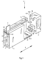
- Figures 1 and 2 show a first example of a designed according to the invention Length measuring device. It consists of a well-known tubular, rectangular housing 1 made of aluminum. In this case 1 is a scale 2, for example made of glass or glass ceramic, attached. The coding 3 of the scale 2 is in operation by a scanning unit 4 scanned. For position measurement, the housing 1 is mounted on mounting blocks 5 on a first object and the scanning unit 4 on a through sealing elements 6 engaging driver 7 on a second object attached.
- the coding 3 can be an incremental division or an absolute one Be a code that is photoelectric, inductive, capacitive or magnetic is designed to be scanned.
- the driver 7 engages through one in the measuring direction X extending slot 8 of the housing 1, the sealing elements 6 in the shown Example roof-like arranged elastic resiliently lying against each other Sealing lips 6.1 and 6.2 are.
- the two front openings of the housing 1 are each by means of a mounting block 5 sealed. For reasons of clarity in the examples described below only one of these assembly blocks 5 shown.
- the end of the housing 1, not shown, is preferably sealed with an identical mounting block 5. Likewise, in the following examples the scale 2 and the scanning unit 4 are not shown.
- the mounting block 5 has a mounting opening 9, via which an attachment can take place on one of the two objects, the relative position of which the length measuring device is to be measured.
- the attachment is in the simplest Case with a large screw through the mounting hole 9 of the mounting block 5 in a threaded bore of the first Property is led.
- An insert part 10 is formed on the mounting block 5.
- This insert part 10 is a projection pointing towards the front opening of the housing 1 a constriction 10.1.
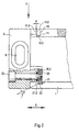
- the housing 1 Corresponding to this is the housing 1 with a Provide recess 11.
- the recess 11 runs largely vertically to the measuring direction X and is a kind of precisely fitting guide for the insert 10.
- the insert part 10 positively engages in the recess 11, as shown in the assembled state in Figure 2.
- the constriction 10.1 of the insert 10 forms transverse to the measuring direction X surfaces 10.2 the surfaces 11.2 which also run transversely to the measuring direction X. Interact recess 11 in the assembled state in a form-fitting manner.
- These surfaces 11.2 of the recess 11 are a kind of undercut on Housing 1.
- the mounting block 5 is relative locked to housing 1 in measuring direction X. This ensures that the assembly blocks 5, when the assembly on the first object is complete, the housing 1 take along in measuring direction X, which means that the housing 1 in the event of temperature changes has the same expansion behavior as the first Object.
- the housing 1 thus adapts to the linear expansion and shrinkage of the first object, e.g. of the machine table made of gray cast iron on.
- the mounting block 5 is mounted on the housing 1 in all of the invention Examples in a simple way by introducing the Mounting block 5 to an end face of the housing 1 and by simple Hooking the insert part 10 into the recess 11 with a relative movement of the mounting block 5 perpendicular to the measuring direction X.
- the insert 10 has surfaces 10.3, the sealing elements 6 are adapted and these surfaces are in the assembled state 10.3 in contact with the sealing elements 6 and effect a seal in this area.
- the insert part 10 can also clamp the sealing element 6 cause by the insert 10 on surfaces of the Housing 1 is pressed.
- At least one of the two surfaces 10.2 and 11.2 does not run exactly at right angles to the measuring direction X, but is somewhat inclined, as can be seen in FIG. 2 is.
- the surface 10.2 of the housing 1 is slightly inclined to when hooking a pressure force acting transversely to the hooking movement between the end faces of the housing 1 and the mounting block 5 to achieve.
- the angle of inclination of the surface 11.2 relative to the normal of the Measuring direction X is shown with ⁇ and is approximately 1 °.
- the direction of the Hooking movement during the assembly of the mounting block 5 on the housing 1 is shown in Figures 1 and 2 with Y. During this hooking movement the surface 10.2 is supported on the inclined surface 11.2, whereby the mounting block 5 to the end faces of the housing 1 in the X direction is pushed.
- a further insert part 20 is additionally attached to the mounting block 5.
- This insert part 20 is also a projection, which is in a recess 21st of the housing 1 engages. Just like the insert 10, so are also on Insert 20 surfaces 20.2 and 21 recesses 21.2 provided on the recess, which run transverse to the measuring direction X and one acting in the measuring direction X. positive locking between the mounting block 5 and the Ensure housing 1.
- the insert 20 is one in the example shown Washer, which has a screw 22 relative to the mounting block 5 in the measuring direction X can be moved. By tightening the screw 22 the two surfaces 20.2 and 21.2 pressed together and the front Surface of the mounting block 5 is on the opposite end Surface of the housing 1 drawn.
- the insert part 20 has an annular cutting edge 23 which extends into the recess 21 of the housing 1 presses and is supported on the mounting block 5.
- the ring cutter 23 also ensures a secure locking of the mounting block 5 transverse to the measuring direction X. This lock is also a Positive locking.
- the angle ⁇ (in relation to the measuring direction X) of the cutting edge 23 is chosen so that when tightening the screw 22 of the mounting block 5 is pushed into the correct position, that is, based on the figure 2 downwards in the Y direction and therefore compulsory because of the angle ⁇ also to the housing 1.
- the penetration of the washer 23 an electrical contact in the housing 1 and in the mounting block 5 between the anodized housing 1 and the anodized mounting block 5.
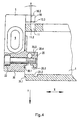
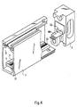
- FIGS. 4, and 5 A second particularly advantageous exemplary embodiment is shown in FIGS. 4, and 5.
- the surfaces 10.2 do not run exactly perpendicular to the X direction but slightly inclined.
- the angle of inclination is marked with ⁇ .
- This has the advantage that between the mounting block 5 and the two legs 1.1 and 1.2 of the housing 1 also a positive Connection exists, which holds the two legs 1.1 and 1.2 together.
- the two legs 1.1 and 1.2 spread apart by the interaction of the inclined surface 10.2 with the surface 11.2 prevented.
- the surface 11.2 can have the same angle of inclination ⁇ , which ensures a good positive fit.
- the further insert part 20 also integrally formed on the mounting block 5.
- the insert 20 is Slidable in the measuring direction X relative to the mounting block 5 via a joint 20.3.
- the joint 20.3 is formed by a weak point joint, by a slot 20.4 between the mounting block 5 and the insert 20 was introduced.
- insert 20 engages in the recess 21 of the housing 1 and the two surfaces 21.2 and 20.2 pressed together by actuating the screw 22.
- the two faces 21.2 and 20.2 form a positive connection acting in the measuring direction X.
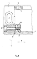
- FIG. 5 shows the fully assembled assembly block 5.
- FIG. 6 shows an addition to the second embodiment.
- the housing 1 and the mounting block 5 have already been described above.
- a contact element 40 which is an electrical conductive connection between the scale 2 and the mounting block 5 guaranteed.
- the scale 2 is usually on a surface of the housing 1 by means of a elastic adhesive layer 31 attached. This adhesive layer 31 is electrical insulating.
- the scale 2 consists of glass or glass ceramic and is thus electrically isolated.
- On the surface of scale 2 is the Coding 3 applied from chrome.
- the scanning unit 4 (FIG. 1) is supported usually via ball bearings or sliding shoes on the surface of the Scale 2 resilient.
- a layer 32 must be removed over the entire length of the scale 2 Chrome applied to the scale surface, which is the markings the coding 3 electrically connects to each other.
- This electrically conductive Layer 32 is at least at one scale end over the contact element 30 electrically connected to the mounting block 5.
- This Contact element 30 provides the electrical connection of layer 32 to one Reference potential since the electrically conductive mounting block 5 on one Machine part is attached electrically conductive and this machine part in turn is connected to the reference potential (earth, ground).
- the reference potential earth, ground
- the contact element 30 is pressed.
- the pressing creates a mechanical connection as well as at the same time an electrically conductive connection because the insulating anodized layer in the Hole is scratched.
- the contact element 30 can also be screwed or rivets are attached to the mounting block 5.
- the contact element 40 is a simple sheet metal part made of electrically conductive Material that is in the assembled state of the mounting block 5 on the Surface of the layer 32 is supported resiliently.
- the use of the contact element 40 is particularly advantageous for electrically non-conductive scales 2 can be used.
- the scale consists of electrically conductive material and this is electrically insulating in the housing 1 fastened, the contact element 40 can also advantageously be used here, by electrically connecting the scale to the mounting block 5.
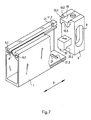
- the third exemplary embodiment according to FIGS. 7 and 8 shows a length measuring device with a mounting block 5 on which the insert 10 the mounting block 5 is screwed.
- the insert 20 is on the assembly block 5 integrally formed and has the projection that into the recess 21 engages in one piece on the mounting block 5.
- Form the insert part 10 and the recess 11 corresponds to the first example.
- the insert part is 10 screwed to the mounting block 5 and otherwise as in the first Example executed.
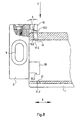
- the insert 20 is made in several parts.
- a first one Part 20.6 is formed on the mounting block 5.
- This part 20.4 reaches in the measuring direction X looks into an intermediate part 20.5 and this Intermediate part 20.5 in the recess 21.
- the intermediate part 20.5 is fixed to the housing 1.
- This one too Embodiments act across the measurement direction X surfaces together to form fit between the mounting block 5 and the To reach housing 1, the mounting block 5 with the housing 1 in Measuring direction X locked and fixed to each other.
- the insert part 10 integrally formed on the mounting block 5 and acts with the recess 11 together in the housing 1 according to the examples described above.
- the further insert part 20 is screwed onto the mounting block 5 and has a projection with a surface 20.2 transverse to the measuring direction X, the cooperates with a corresponding surface 21.2 of the housing 1, to positively lock the mounting block 5 on the housing 1.
- a screw 24 which is transverse to Measuring direction X is screwed through the housing 1 and the insert 20.
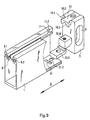
- Insert part 10 and the recess 11 executed as already explained.
- a fuse is provided, which consists of the insert 20.
- the insert 20 is formed as a projection on the mounting block 5 and has a bore running transversely to the measuring direction X.
- a corresponding bore is provided through which the insert part 20 screwed to the mounting block 5 transversely to the measuring direction X via the screw 25 becomes.
- the backup takes place with the insert part 20, which is screwed onto the mounting block 5 and form-fitting engages in a recess 21 of the housing 1.
- the fixation transversely to the measuring direction X takes place through the surfaces 20.2 and 21.2.
- the insert part 10 and the recess 11 is in accordance with the other embodiments designed.
- a secure seal can be made between the front End of the housing 1 and the mounting block 5, a sealing material, for example a sealing washer or a sealing ring can be introduced.
Landscapes
- Physics & Mathematics (AREA)
- General Physics & Mathematics (AREA)
- Length Measuring Devices With Unspecified Measuring Means (AREA)
- A Measuring Device Byusing Mechanical Method (AREA)
Description
- Figur 1
- eine erste Längenmeßeinrichtung;
- Figur 2
- einen Schnitt der Längenmeßeinrichtung nach Figur 1;
- Figur 3
- eine zweite Längenmeßeinrichtung;
- Figur 4
- einen Schnitt der Längenmeßeinrichtung nach Figur 3 während der Montage;
- Figur 5
- einen Schnitt der Längenmeßeinrichtung nach Figur 3 im fertig montierten Zustand;
- Figur 6
- die zweite Längenmeßeinrichtung mit einem Kontaktelement;
- Figur 7
- eine dritte Längenmeßeinrichtung;
- Figur 8
- einen Schnitt der Längenmeßeinrichtung nach Figur 7;
- Figur 9
- eine vierte Längenmeßeinrichtung;
- Figur 10
- einen Schnitt der vierten Längenmeßeinrichtung;
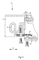
- Figur 11
- einen Schnitt einer fünften Längenmeßeinrichtung;
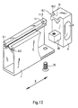
- Figur 12
- eine sechste Längenmeßeinrichtung;
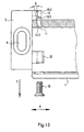
- Figur 13
- einen Schnitt der Längenmeßeinrichtung nach Figur 12 und
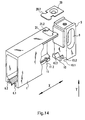
- Figur 14
- eine siebte Längenmeßeinrichtung.
Claims (16)
- Längenmeßeinrichtung mit einem in Meßrichtung (X) verlaufend innerhalb eines rohrförmigen Gehäuses (1) angeordneten Maßstab (2) und einer innerhalb des Gehäuses längsverschiebbaren Abtasteinheit (4) zur Abtastung des Maßstabes (2), wobei jedes der stirnseitigen Enden des Gehäuses (1) durch einen Montageblock (5) abgeschlossen ist, mit dem das Gehäuse (1) an einem zu messenden Objekt befestigbar ist, dadurch gekennzeichnet, daß an dem Montageblock (5) zumindest ein Einsatzteil (10, 20) befestigt oder angeformt ist, das in eine Aussparung (11, 21) des Gehäuses (1) eingreift und durch diesen Eingriff der Montageblock (5) gegenüber dem Gehäuse (1) in Meßrichtung (X) formschlüssig arretiert ist.
- Längenmeßeinrichtung nach Anspruch 1, dadurch gekennzeichnet, daß das Einsatzteil (10) einen Vorsprung mit einer Aussparung (10.1) aufweist, durch die quer zur Meßrichtung (X) verlaufende Flächen (10.2) gebildet werden, die mit ebenfalls quer zur Meßrichtung (X) verlaufenden Flächen (11.2) der Aussparung (11) des Gehäuses (1) formschlüssig zusammenwirken.
- Längenmeßeinrichtung nach einem der Ansprüche 1 oder 2, dadurch gekennzeichnet, daß die Aussparung (11) im Gehäuse (1) quer zur Meßrichtung (X) verläuft und eine quer zur Meßrichtung (X) verlaufende Führung des Einsatzteiles (10) bei der Montage bildet.
- Längenmeßeinrichtung nach Anspruch 3, dadurch gekennzeichnet, daß das Gehäuse (1) einen in Meßrichtung (X) verlaufenden Schlitz (8) aufweist, der über ein Dichtelement abgedichtet ist, und daß die Aussparung (11) außerhalb des abgedichteten Hohlraumes des Gehäuses (1) angeordnet ist.
- Längenmeßeinrichtung nach einem der Ansprüche 1 bis 4, dadurch gekennzeichnet, daß das Gehäuse (1) einen in Meßrichtung (X) verlaufenden Schlitz (8) aufweist und beidseitig des Schlitzes (8) ein Schenkel (1.1, 1.2) des Gehäuses (1) verläuft, daß weiterhin in jedem dieser Schenkel (1.2, 1.2) eine quer zur Meßrichtung (X) verlaufende Aussparung (11) eingebracht ist, in die jeweils ein Einsatzteil (10) oder ein Bereich eines gemeinsamen Einsatzteiles (10) formschlüssig eingreift, wobei der Formschluß in Meßrichtung (X) sowie in zumindest eine quer dazu verlaufende Richtung wirkt.
- Längenmeßeinrichtung nach einem der Ansprüche 2 bis 4, dadurch gekennzeichnet, daß zumindest eine der beiden Flächen (10.2, 11.2) mit einem kleinen Winkel () von etwa 1° zur Normalen der Meßrichtung (X) derart geneigt ist, daß beim Einhaken des Einsatzteiles (10) durch das Zusammenwirken der beiden Flächen (10.2, 11.2) der Montageblock (5) an die stirnseitig abzudichtende Fläche des Gehäuses (1) gedrängt wird.
- Längenmeßeinrichtung nach Anspruch 4, dadurch gekennzeichnet, daß das Einsatzteil (10) eine Fläche (10.3) aufweist, die quer zur Meßrichtung (X) verläuft und mit dem Dichtelement (6) in Kontakt steht.
- Längenmeßeinrichtung nach Anspruch 1, dadurch gekennzeichnet, daß mehrere Einsatzteile (10, 20) am Montageblock (5) vorgesehen sind, die in Aussparungen (11, 21) des Gehäuses (1) formschlüssig eingreifen.
- Längenmeßeinrichtung nach Anspruch 8, dadurch gekennzeichnet, daß eines der Einsatzteile (20) am Montageblock (5) in Meßrichtung (X) verschiebbar oder verschwenkbar gelagert ist und durch Verschiebung des Einsatzteiles (20) eine in Meßrichtung (X) wirkende Verspannung zwischen dem Montageblock (5) und dem Gehäuse (1) erzielt wird.
- Längenmeßeinrichtung nach Anspruch 9, dadurch gekennzeichnet, daß das Einsatzteil (20) einen Vorsprung (23) aufweist, der in die Aussparung (21) des Gehäuses (1) eingreift und einen quer zur Meßrichtung (X) wirkenden Formschluß bildet.
- Längenmeßeinrichtung nach Anspruch 10, dadurch gekennzeichnet, daß der Vorsprung eine Ringschneide (23) ist.
- Längenmeßeinrichtung nach einem der vorhergehenden Ansprüche, dadurch gekennzeichnet, daß am Montageblock (5) eine Fläche (30.1) angeordnet ist, die mit einer Fläche (31.1) des Gehäuses (1) zusammenwirkt und einen quer zur Meßrichtung (X) wirkenden Formschluß bildet.
- Längenmeßeinrichtung nach einem der vorhergehenden Ansprüche, dadurch gekennzeichnet, daß am Montageblock (5) ein elektrisch leitendes Kontaktelement (40) angebracht ist, das einen elektrischen Kontakt zwischen dem Maßstab (2) und dem Montageblock (5) herstellt.
- Längenmeßeinrichtung nach Anspruch 13, dadurch gekennzeichnet, daß das Kontaktelement (40) ein federndes Teil ist, das federnd an einer elektrisch leitenden Oberfläche des Maßstabes (2) aufliegt.
- Verfahren zur Montage einer Längenmeßeinrichtung, die ein rohrförmiges Gehäuse (1) mit einem Maßstab (2) aufweist, dadurch gekennzeichnet, daß ein Montageblock (5) nach folgendem Verfahrensschritt an einer stirnseitigen Öffnung des Gehäuses (1) montiert wird: Einhaken eines am Montageblock (5) angebrachten Einsatzteiles (10, 20) in eine quer zur Meßrichtung (X) verlaufende Aussparung (11, 21) und Bewegung des Montageblockes (5) quer zur Meßrichtung (X).
- Verfahren nach Anspruch 15, dadurch gekennzeichnet, daß während der Bewegung des Montageblockes (5) quer zur Meßrichtung (X) ein am Montageblock (5) angebrachtes Kontaktelement (30) mit einer Oberfläche des Maßstabes (2) in elektrisch leitenden Kontakt gebracht wird.
Applications Claiming Priority (4)
| Application Number | Priority Date | Filing Date | Title |
|---|---|---|---|
| DE19646464 | 1996-11-11 | ||
| DE19646464 | 1996-11-11 | ||
| DE19711753 | 1997-03-21 | ||
| DE19711753A DE19711753A1 (de) | 1996-11-11 | 1997-03-21 | Längenmeßeinrichtung |
Publications (3)
| Publication Number | Publication Date |
|---|---|
| EP0841540A2 EP0841540A2 (de) | 1998-05-13 |
| EP0841540A3 EP0841540A3 (de) | 1999-11-03 |
| EP0841540B1 true EP0841540B1 (de) | 2001-08-22 |
Family
ID=26031167
Family Applications (1)
| Application Number | Title | Priority Date | Filing Date |
|---|---|---|---|
| EP97119509A Expired - Lifetime EP0841540B1 (de) | 1996-11-11 | 1997-11-07 | Längenmesseinrichtung |
Country Status (5)
| Country | Link |
|---|---|
| US (1) | US5832616A (de) |
| EP (1) | EP0841540B1 (de) |
| JP (1) | JP3550005B2 (de) |
| AT (1) | ATE204646T1 (de) |
| ES (1) | ES2160294T3 (de) |
Families Citing this family (13)
| Publication number | Priority date | Publication date | Assignee | Title |
|---|---|---|---|---|
| DE19912310B4 (de) * | 1999-03-19 | 2007-11-29 | Dr. Johannes Heidenhain Gmbh | Positionsmeßeinrichtung |
| DE19914311A1 (de) * | 1999-03-29 | 2000-10-05 | Heidenhain Gmbh Dr Johannes | Verfahren und Vorrichtung zum Anbringen eines Maßstabes |
| DE10056947A1 (de) * | 2000-11-17 | 2002-05-23 | Optolab Licensing Gmbh | Verfahren und Anordnung zur Montage von Messsystemen |
| DE10204611B4 (de) * | 2002-02-05 | 2007-04-05 | Dr. Johannes Heidenhain Gmbh | Verfahren und Vorrichtung zum Anbringen eines Maßstabes oder Maßstabträgers |
| US6612047B1 (en) * | 2002-02-19 | 2003-09-02 | Acu-Rite, Inc. | Length measuring device |
| DE102006004898A1 (de) * | 2006-02-03 | 2007-08-09 | Dr. Johannes Heidenhain Gmbh | Abtastsystem einer Positionsmesseinrichtung |
| JP2009180525A (ja) * | 2008-01-29 | 2009-08-13 | Mitsutoyo Corp | 測定装置 |
| DE102009043293A1 (de) * | 2009-09-29 | 2011-03-31 | Dr. Johannes Heidenhain Gmbh | Längenmesseinrichtung |
| DE102012203193A1 (de) * | 2012-03-01 | 2013-09-05 | Dr. Johannes Heidenhain Gmbh | Längenmesseinrichtung |
| DE102012203220A1 (de) * | 2012-03-01 | 2013-09-05 | Dr. Johannes Heidenhain Gmbh | Längenmesseinrichtung |
| US9791254B2 (en) * | 2014-12-27 | 2017-10-17 | Mitutoyo Corporation | Scale fixating device |
| EP3276310B1 (de) * | 2016-07-27 | 2018-09-19 | Dr. Johannes Heidenhain GmbH | Längenmesseinrichtung |
| ES2693900T3 (es) * | 2016-08-02 | 2018-12-14 | Dr. Johannes Heidenhain Gmbh | Dispositivo de medición de la longitud |
Family Cites Families (13)
| Publication number | Priority date | Publication date | Assignee | Title |
|---|---|---|---|---|
| US4198757A (en) * | 1976-07-09 | 1980-04-22 | Dr. Johannes Heidenhain Gmbh | Fastening apparatus for longitudinal measuring system |
| DE2853771C2 (de) * | 1978-12-13 | 1986-08-28 | Dr. Johannes Heidenhain Gmbh, 8225 Traunreut | Längenmeßeinrichtung |
| DE3302643C2 (de) * | 1983-01-27 | 1987-01-08 | Dr. Johannes Heidenhain Gmbh, 8225 Traunreut | Spanneinrichtung für eine Längenmeßeinrichtung |
| DE3316082A1 (de) * | 1983-05-03 | 1984-11-08 | Dr. Johannes Heidenhain Gmbh, 8225 Traunreut | Messeinrichtung |
| US4649648A (en) * | 1984-08-31 | 1987-03-17 | Sony Magnescale Incorporation | Linear scale |
| JPS6358107A (ja) * | 1986-08-28 | 1988-03-12 | Sony Magnescale Inc | スケ−ル装置の保持機構 |
| US4991311A (en) * | 1986-08-28 | 1991-02-12 | Sony Corporation | Mounting structure for magnetic linear scale unit |
| DE3719409A1 (de) * | 1987-06-11 | 1988-12-22 | Heidenhain Gmbh Dr Johannes | Positionsmesseinrichtung |
| DE3850762T3 (de) * | 1987-10-14 | 1999-09-30 | Linear System S.R.L., Monza | Optischer Massstab. |
| DE3820331A1 (de) * | 1988-06-15 | 1989-12-21 | Heidenhain Gmbh Dr Johannes | Sicherungsvorrichtung fuer eine messeinrichtung |
| DD276726A1 (de) * | 1988-11-07 | 1990-03-07 | Zeiss Jena Veb Carl | Laengenmesssystem mit havariesicherung |
| JPH02241984A (ja) * | 1989-03-15 | 1990-09-26 | Mitsubishi Electric Corp | 回転角度検出装置 |
| DE4406799C2 (de) * | 1994-03-02 | 1997-11-06 | Heidenhain Gmbh Dr Johannes | Positionsmeßeinrichtung |
-
1997
- 1997-11-07 AT AT97119509T patent/ATE204646T1/de not_active IP Right Cessation
- 1997-11-07 EP EP97119509A patent/EP0841540B1/de not_active Expired - Lifetime
- 1997-11-07 ES ES97119509T patent/ES2160294T3/es not_active Expired - Lifetime
- 1997-11-10 JP JP30748097A patent/JP3550005B2/ja not_active Expired - Lifetime
- 1997-11-12 US US08/967,866 patent/US5832616A/en not_active Expired - Lifetime
Also Published As
| Publication number | Publication date |
|---|---|
| EP0841540A3 (de) | 1999-11-03 |
| ATE204646T1 (de) | 2001-09-15 |
| ES2160294T3 (es) | 2001-11-01 |
| JPH10221002A (ja) | 1998-08-21 |
| EP0841540A2 (de) | 1998-05-13 |
| JP3550005B2 (ja) | 2004-08-04 |
| US5832616A (en) | 1998-11-10 |
Similar Documents
| Publication | Publication Date | Title |
|---|---|---|
| DE19739298C1 (de) | Vorrichtung zur Befestigung eines Entfernungssensors an einem Kraftfahrzeug | |
| EP0841540B1 (de) | Längenmesseinrichtung | |
| DE69405589T2 (de) | Scheibenbremse mit erhöhter sicherheit | |
| EP2634539B1 (de) | Längenmesseinrichtung | |
| EP0513406A1 (de) | Positionsmesseinrichtung | |
| WO2001059898A1 (de) | Vorrichtung zur befestigung von schaltgeräten auf tragschienen | |
| EP2570779B1 (de) | Montagevorrichtung eines Längenmesssystems | |
| AT389944B (de) | Kapazitives messsystem zur abstandsbestimmung | |
| CH698426B1 (de) | Halterung für einen Drucksensor sowie Messrolle mit einem Drucksensor. | |
| DE19711753A1 (de) | Längenmeßeinrichtung | |
| DE3435758C2 (de) | ||
| WO1998025284A1 (de) | Sicherheitsschalter | |
| DE10330955B4 (de) | Positionsmessgerät und Verfahren zur Montage eines derartigen Positionsmessgerätes | |
| DE3131505C2 (de) | ||
| DE69313730T2 (de) | Schalthebel, insbesondere für ein Kraftfahrzeug | |
| EP1764584B1 (de) | Befestigung eines Trägers einer Massverkörperung | |
| DE102022115527B4 (de) | Befestigungssystem | |
| DE102020103627A1 (de) | Federstiftstossverbinder | |
| DE3834439A1 (de) | Klemmstueck fuer messtaster | |
| EP0039456A1 (de) | Verkokungsofentür | |
| DE19631941C2 (de) | Befestigung für eine Abdeckung | |
| DE68920156T2 (de) | Lastanzeiger. | |
| DE3323785A1 (de) | Vorrichtung zur laengseinstellung der legeschienen einer kettenwirkmaschine | |
| EP1446586A1 (de) | Hohlkammerprofilsystem für präzisionsaufbauten | |
| EP0184004A2 (de) | Einsteckschloss mit Profilzylinder |
Legal Events
| Date | Code | Title | Description |
|---|---|---|---|
| PUAI | Public reference made under article 153(3) epc to a published international application that has entered the european phase |
Free format text: ORIGINAL CODE: 0009012 |
|
| AK | Designated contracting states |
Kind code of ref document: A2 Designated state(s): AT CH DE ES FR GB IT LI |
|
| AX | Request for extension of the european patent |
Free format text: AL;LT;LV;MK;RO;SI |
|
| PUAL | Search report despatched |
Free format text: ORIGINAL CODE: 0009013 |
|
| AK | Designated contracting states |
Kind code of ref document: A3 Designated state(s): AT BE CH DE DK ES FI FR GB GR IE IT LI LU MC NL PT SE |
|
| RIC1 | Information provided on ipc code assigned before grant |
Free format text: 6G 01D 5/347 A, 6G 01B 5/00 B |
|
| 17P | Request for examination filed |
Effective date: 20000503 |
|
| AKX | Designation fees paid |
Free format text: AT CH DE ES FR GB IT LI |
|
| GRAG | Despatch of communication of intention to grant |
Free format text: ORIGINAL CODE: EPIDOS AGRA |
|
| GRAG | Despatch of communication of intention to grant |
Free format text: ORIGINAL CODE: EPIDOS AGRA |
|
| GRAH | Despatch of communication of intention to grant a patent |
Free format text: ORIGINAL CODE: EPIDOS IGRA |
|
| 17Q | First examination report despatched |
Effective date: 20010118 |
|
| GRAH | Despatch of communication of intention to grant a patent |
Free format text: ORIGINAL CODE: EPIDOS IGRA |
|
| ITF | It: translation for a ep patent filed | ||
| GRAA | (expected) grant |
Free format text: ORIGINAL CODE: 0009210 |
|
| AK | Designated contracting states |
Kind code of ref document: B1 Designated state(s): AT CH DE ES FR GB IT LI |
|
| REF | Corresponds to: |
Ref document number: 204646 Country of ref document: AT Date of ref document: 20010915 Kind code of ref document: T |
|
| REG | Reference to a national code |
Ref country code: CH Ref legal event code: NV Representative=s name: TROESCH SCHEIDEGGER WERNER AG Ref country code: CH Ref legal event code: EP |
|
| REF | Corresponds to: |
Ref document number: 59704360 Country of ref document: DE Date of ref document: 20010927 |
|
| REG | Reference to a national code |
Ref country code: ES Ref legal event code: FG2A Ref document number: 2160294 Country of ref document: ES Kind code of ref document: T3 |
|
| GBT | Gb: translation of ep patent filed (gb section 77(6)(a)/1977) |
Effective date: 20011117 |
|
| REG | Reference to a national code |
Ref country code: GB Ref legal event code: IF02 |
|
| ET | Fr: translation filed | ||
| PLBE | No opposition filed within time limit |
Free format text: ORIGINAL CODE: 0009261 |
|
| STAA | Information on the status of an ep patent application or granted ep patent |
Free format text: STATUS: NO OPPOSITION FILED WITHIN TIME LIMIT |
|
| 26N | No opposition filed | ||
| PGFP | Annual fee paid to national office [announced via postgrant information from national office to epo] |
Ref country code: AT Payment date: 20081114 Year of fee payment: 12 |
|
| PG25 | Lapsed in a contracting state [announced via postgrant information from national office to epo] |
Ref country code: AT Free format text: LAPSE BECAUSE OF NON-PAYMENT OF DUE FEES Effective date: 20091107 |
|
| PGFP | Annual fee paid to national office [announced via postgrant information from national office to epo] |
Ref country code: FR Payment date: 20121130 Year of fee payment: 16 |
|
| PGFP | Annual fee paid to national office [announced via postgrant information from national office to epo] |
Ref country code: IT Payment date: 20121123 Year of fee payment: 16 Ref country code: GB Payment date: 20121120 Year of fee payment: 16 |
|
| GBPC | Gb: european patent ceased through non-payment of renewal fee |
Effective date: 20131107 |
|
| REG | Reference to a national code |
Ref country code: FR Ref legal event code: ST Effective date: 20140731 |
|
| PG25 | Lapsed in a contracting state [announced via postgrant information from national office to epo] |
Ref country code: IT Free format text: LAPSE BECAUSE OF NON-PAYMENT OF DUE FEES Effective date: 20131107 |
|
| PG25 | Lapsed in a contracting state [announced via postgrant information from national office to epo] |
Ref country code: GB Free format text: LAPSE BECAUSE OF NON-PAYMENT OF DUE FEES Effective date: 20131107 Ref country code: FR Free format text: LAPSE BECAUSE OF NON-PAYMENT OF DUE FEES Effective date: 20131202 |
|
| PGFP | Annual fee paid to national office [announced via postgrant information from national office to epo] |
Ref country code: CH Payment date: 20141119 Year of fee payment: 18 |
|
| PGFP | Annual fee paid to national office [announced via postgrant information from national office to epo] |
Ref country code: DE Payment date: 20151119 Year of fee payment: 19 |
|
| PGFP | Annual fee paid to national office [announced via postgrant information from national office to epo] |
Ref country code: ES Payment date: 20151111 Year of fee payment: 19 |
|
| REG | Reference to a national code |
Ref country code: CH Ref legal event code: PL |
|
| PG25 | Lapsed in a contracting state [announced via postgrant information from national office to epo] |
Ref country code: LI Free format text: LAPSE BECAUSE OF NON-PAYMENT OF DUE FEES Effective date: 20151130 Ref country code: CH Free format text: LAPSE BECAUSE OF NON-PAYMENT OF DUE FEES Effective date: 20151130 |
|
| REG | Reference to a national code |
Ref country code: DE Ref legal event code: R119 Ref document number: 59704360 Country of ref document: DE |
|
| PG25 | Lapsed in a contracting state [announced via postgrant information from national office to epo] |
Ref country code: DE Free format text: LAPSE BECAUSE OF NON-PAYMENT OF DUE FEES Effective date: 20170601 |
|
| REG | Reference to a national code |
Ref country code: ES Ref legal event code: FD2A Effective date: 20180507 |
|
| PG25 | Lapsed in a contracting state [announced via postgrant information from national office to epo] |
Ref country code: ES Free format text: LAPSE BECAUSE OF FAILURE TO SUBMIT A TRANSLATION OF THE DESCRIPTION OR TO PAY THE FEE WITHIN THE PRESCRIBED TIME-LIMIT Effective date: 20010822 |
|
| PG25 | Lapsed in a contracting state [announced via postgrant information from national office to epo] |
Ref country code: ES Free format text: LAPSE BECAUSE OF FAILURE TO SUBMIT A TRANSLATION OF THE DESCRIPTION OR TO PAY THE FEE WITHIN THE PRESCRIBED TIME-LIMIT Effective date: 20161108 |
|
| RIC2 | Information provided on ipc code assigned after grant |
Ipc: G01B 5/00 20060101ALI19990915BHEP Ipc: G01D 5/347 20060101AFI19980318BHEP |