EP1040976B1 - Bremskraftverstärkungsvorrichtung - Google Patents
Bremskraftverstärkungsvorrichtung Download PDFInfo
- Publication number
- EP1040976B1 EP1040976B1 EP00106738A EP00106738A EP1040976B1 EP 1040976 B1 EP1040976 B1 EP 1040976B1 EP 00106738 A EP00106738 A EP 00106738A EP 00106738 A EP00106738 A EP 00106738A EP 1040976 B1 EP1040976 B1 EP 1040976B1
- Authority
- EP
- European Patent Office
- Prior art keywords
- pressure chamber
- brake pedal
- piston
- variable
- operating rod
- Prior art date
- Legal status (The legal status is an assumption and is not a legal conclusion. Google has not performed a legal analysis and makes no representation as to the accuracy of the status listed.)
- Expired - Lifetime
Links
Images


Classifications
-
- F—MECHANICAL ENGINEERING; LIGHTING; HEATING; WEAPONS; BLASTING
- F04—POSITIVE - DISPLACEMENT MACHINES FOR LIQUIDS; PUMPS FOR LIQUIDS OR ELASTIC FLUIDS
- F04B—POSITIVE-DISPLACEMENT MACHINES FOR LIQUIDS; PUMPS
- F04B49/00—Control, e.g. of pump delivery, or pump pressure of, or safety measures for, machines, pumps, or pumping installations, not otherwise provided for, or of interest apart from, groups F04B1/00 - F04B47/00
- F04B49/10—Other safety measures
-
- B—PERFORMING OPERATIONS; TRANSPORTING
- B60—VEHICLES IN GENERAL
- B60T—VEHICLE BRAKE CONTROL SYSTEMS OR PARTS THEREOF; BRAKE CONTROL SYSTEMS OR PARTS THEREOF, IN GENERAL; ARRANGEMENT OF BRAKING ELEMENTS ON VEHICLES IN GENERAL; PORTABLE DEVICES FOR PREVENTING UNWANTED MOVEMENT OF VEHICLES; VEHICLE MODIFICATIONS TO FACILITATE COOLING OF BRAKES
- B60T13/00—Transmitting braking action from initiating means to ultimate brake actuator with power assistance or drive; Brake systems incorporating such transmitting means, e.g. air-pressure brake systems
- B60T13/10—Transmitting braking action from initiating means to ultimate brake actuator with power assistance or drive; Brake systems incorporating such transmitting means, e.g. air-pressure brake systems with fluid assistance, drive, or release
- B60T13/24—Transmitting braking action from initiating means to ultimate brake actuator with power assistance or drive; Brake systems incorporating such transmitting means, e.g. air-pressure brake systems with fluid assistance, drive, or release the fluid being gaseous
- B60T13/46—Vacuum systems
- B60T13/52—Vacuum systems indirect, i.e. vacuum booster units
- B60T13/569—Vacuum systems indirect, i.e. vacuum booster units characterised by piston details, e.g. construction, mounting of diaphragm
-
- B—PERFORMING OPERATIONS; TRANSPORTING
- B60—VEHICLES IN GENERAL
- B60T—VEHICLE BRAKE CONTROL SYSTEMS OR PARTS THEREOF; BRAKE CONTROL SYSTEMS OR PARTS THEREOF, IN GENERAL; ARRANGEMENT OF BRAKING ELEMENTS ON VEHICLES IN GENERAL; PORTABLE DEVICES FOR PREVENTING UNWANTED MOVEMENT OF VEHICLES; VEHICLE MODIFICATIONS TO FACILITATE COOLING OF BRAKES
- B60T13/00—Transmitting braking action from initiating means to ultimate brake actuator with power assistance or drive; Brake systems incorporating such transmitting means, e.g. air-pressure brake systems
- B60T13/10—Transmitting braking action from initiating means to ultimate brake actuator with power assistance or drive; Brake systems incorporating such transmitting means, e.g. air-pressure brake systems with fluid assistance, drive, or release
- B60T13/24—Transmitting braking action from initiating means to ultimate brake actuator with power assistance or drive; Brake systems incorporating such transmitting means, e.g. air-pressure brake systems with fluid assistance, drive, or release the fluid being gaseous
- B60T13/46—Vacuum systems
- B60T13/52—Vacuum systems indirect, i.e. vacuum booster units
- B60T13/57—Vacuum systems indirect, i.e. vacuum booster units characterised by constructional features of control valves
-
- B—PERFORMING OPERATIONS; TRANSPORTING
- B60—VEHICLES IN GENERAL
- B60T—VEHICLE BRAKE CONTROL SYSTEMS OR PARTS THEREOF; BRAKE CONTROL SYSTEMS OR PARTS THEREOF, IN GENERAL; ARRANGEMENT OF BRAKING ELEMENTS ON VEHICLES IN GENERAL; PORTABLE DEVICES FOR PREVENTING UNWANTED MOVEMENT OF VEHICLES; VEHICLE MODIFICATIONS TO FACILITATE COOLING OF BRAKES
- B60T8/00—Arrangements for adjusting wheel-braking force to meet varying vehicular or ground-surface conditions, e.g. limiting or varying distribution of braking force
- B60T8/32—Arrangements for adjusting wheel-braking force to meet varying vehicular or ground-surface conditions, e.g. limiting or varying distribution of braking force responsive to a speed condition, e.g. acceleration or deceleration
- B60T8/321—Arrangements for adjusting wheel-braking force to meet varying vehicular or ground-surface conditions, e.g. limiting or varying distribution of braking force responsive to a speed condition, e.g. acceleration or deceleration deceleration
- B60T8/3255—Systems in which the braking action is dependent on brake pedal data
- B60T8/3275—Systems with a braking assistant function, i.e. automatic full braking initiation in dependence of brake pedal velocity
-
- F—MECHANICAL ENGINEERING; LIGHTING; HEATING; WEAPONS; BLASTING
- F04—POSITIVE - DISPLACEMENT MACHINES FOR LIQUIDS; PUMPS FOR LIQUIDS OR ELASTIC FLUIDS
- F04B—POSITIVE-DISPLACEMENT MACHINES FOR LIQUIDS; PUMPS
- F04B49/00—Control, e.g. of pump delivery, or pump pressure of, or safety measures for, machines, pumps, or pumping installations, not otherwise provided for, or of interest apart from, groups F04B1/00 - F04B47/00
- F04B49/06—Control using electricity
- F04B49/065—Control using electricity and making use of computers
Definitions
- the present invention relates to a brake booster apparatus and more particularly to a brake power assist apparatus of a vacuum type.
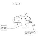
- a brake booster apparatus of a vacuum type as shown, for instance, in Fig. 4 is used in general for a brake booster apparatus for a vehicle.
- a booster (a) of a vacuum type provided between a brake pedal (p) and a master cylinder (m) the interior of a shell thereof is divided into a constant pressure chamber (b) and a variable pressure chamber (c) by a diaphragm (d), and when the brake pedal (p) is not operated, a vacuum from a vacuum source such as an intake manifold is led into both the constant pressure chamber (b) and the variable pressure chamber (c), and thus the diaphragm (d) remains unoperative.
- a vacuum source such as an intake manifold
- a valve mechanism not shown, is opened via an operating rod (e), an outside air (atmospheric pressure) is introduced into the variable pressure chamber (c) to thereby produce a pressure difference between the variable pressure chamber (c) and the constant pressure chamber (b) , and the diaphragm (d) is sucked and actuated forward by this pressure difference. Then, the operating force of the diaphragm (d) is added to the depression force of the brake pedal (p), and a push rod (not shown) then forcibly actuates a piston (not shown) of the master cylinder (m) .
- US-A-4 565 067 relates to a brake system for vehicles comprising such a booster unit.
- a stepped portion (702) with a tapered portion (697) is formed in the inside of valve seat (592) and a first orifice (712) is formed between the stepped portion (702) and the inner peripheral portion of the valve member (622) wherein the rate of introduction of air into the variable pressure chamber is varied depending on the depression stroke of the pedal.
- the booster of a vacuum type is constructed such that the pressure difference between the constant pressure chamber (b) and the variable pressure chamber (c), i.e., the force sucking the diaphragm (d) is added to the pedal (p) depression force to thereby produce a force for pushing the piston of the master cylinder (m), even female and aged drivers, who tend to be regarded as not being strong, can operate the brakes relatively easily.
- a booster of a vacuum type as described above was developed and is disclosed in Japanese Unexamined Patent publication No. Toku-Kai-Sho 61-163051, and in this disclosed booster, a variable throttle valve is provided at a position along an inlet passage of the atmospheric pressure into a variable pressure chamber (c), and the throttling of this variable throttle valve is regulated via a controller by operating a manual switch to close it.
- the way to depress the brake pedal and depression force applied thereto depend on drivers, and a preferable braking performance relative to a depression force applied to the brake pedal also depends on drivers.
- the prior art described above is effective in that the performance of the booster is suitably set depending on the habit or preference of drivers themselves in which the degree of throttling the variable throttle valve is regulated by operating the manual switch.
- An object of the present invention is to solve the aforesaid problem inherent in the prior art booster.
- the present invention which is represented by the features of claim 1, provides a brake booster of a negative pressure type constructed such that a valve mechanism is opened by actuating an operating rod in an axial direction by depressing a brake pedal, so that an atmospheric pressure is allowed to flow into a variable pressure chamber from the valve mechanism, whereby a diaphragm is sucked to be actuated by virtue of a negative pressure in a constant pressure chamber and an operating force of the diaphragm is added to the depression force of the brake pedal to thereby forcibly actuate a piston of a master cylinder
- the brake booster of a negative pressure type comprising a throttling mechanism for varying the inlet volume per unit time of the atmospheric pressure into the variable pressure chamber in response to a depression stroke of the brake pedal, the throttling mechanism being constituted by a position variable piston fixed to the operating rod adapted to be actuated in the axial direction in response to a depression of the brake pedal and a circumferential wall portion surrounding an outer circumference of the
- Fig. 1 is a vertical sectional view showing an embodiment of a booster of a negative pressure type to which the present invention is to be applied, and the booster basically comprises an operating rod 1 connected to a brake pedal, which is not shown, at one end thereof, a valve mechanism 2 adapted to be actuated through an axial stroke of the operating rod 1, a diaphragm 3 partitioning the interior of a shell into a constant pressure chamber 4 and a variable pressure chamber 5, a push rod 6 and a return spring 7.
- valve plunger 22 When the brake pedal is stepped on, the valve plunger 22 is pushed forward (leftward as seen in the figure) via the operating rod 1, and this creates a gap between the seal 23 and the valve plunger 22 (the valve mechanism 2 is opened), whereby the atmospheric pressure comes into the variable pressure chamber 5 through a filter silencer 8.
- the atmospheric pressure flows into the variable pressure chamber 5, there is caused a pressure difference between the variable pressure chamber 5 and the constant pressure chamber 4, and the diaphragm 3 is sucked forward by virtue of the pressure difference so produced.
- valve body 21 fixed to the diaphragm 3 moves forward, and the push rod 6 then pushes and actuates a piston in a master cylinder for braking with a force constituted by the brake pedal depression force and the aforesaid sucking force which sucks the diaphragm 3 forward, a great magnitude of master cylinder actuating pressure being thus obtained with a small magnitude of brake pedal depression force.
- a vacuum booster as described above has conventionally been used in brake systems of general passenger vehicles and been well known, and therefore a further description thereof will be omitted.
- the throttling mechanism for varying an inlet volume per unit time of the atmospheric pressure into the variable pressure chamber 5 in response to the stroke of the brake pedal when it is depressed (in other words, the stroke of the operating rod 1 in the axial direction), and to be specific, the throttling mechanism comprises a position variable piston which varies its position in response to the brake pedal depression stroke and a circumferential wall portion surrounding a circumferential portion of the position variable piston with a certain gap being formed therebetween.
- the opening area of an atmospheric pressure inlet passage constituted by the gap formed between the outer circumference of the position variable piston and the circumferential wall portion is varied to thereby vary the inlet volume per unit time of the atmospheric pressure into the variable pressure chamber 5.
- a throttling mechanism 10 comprises a position variable piston 11 screw fixed to an operating piston 1, a cylindrical portion 12 secured to a rear end of a shell in such a manner as to surround the outer circumference of an atmospheric pressure inlet port 9 of the vacuum booster and a circumferential wall portion 13 formed by drawing inwardly a rear of the cylindrical portion 12, whereby a gap 14 formed between an outer circumferential surface of the position variable piston 11 and an internal surface of the circumferential wall portion 13 is constructed so as to constitute an inlet passage of the atmospheric pressure into the variable pressure chamber 5.
- the position variable piston 11 has a shape configured, as shown, to comprise contiguously a large diameter portion 11a extending over a predetermined extent at a front end portion of the piston 11, an inclined portion 11b following a rear of the large diameter portion 11a in such a manner as be gradually reduced in diameter and a smallest diameter portion 11c following a rear of the inclined portion 11b.
- the position variable piston 11 is constructed such that in a state in which the brake pedal is not operated, the large diameter portion 11a is located inwardly of the circumferential wall portion 13, when a predetermined gap is formed between an outer circumferential surface of the large diameter portion 11a and an internal circumferential surface of the circumferential wall portion 13.
- a valve mechanism is put in an opened state when an operating rod is moved forward in conjunction with a depression of the brake pedal, and the atmospheric pressure flows from an atmospheric pressure inlet port 9 into the variable pressure chamber 5 via a filter silencer 8 after passing through the gap 14 formed as an inlet passage between the position variable piston 11 and the circumferential wall portion 13.
- the gap 14 is being in a doughnut-like configuration and hence it is still narrow. Consequently, the inlet volume per unit time of the atmospheric pressure into the variable pressure chamber 5 is small, and the effect or response of the booster remains sluggish.
- the position variable piston 11 is also moved forward together with the -operating rod 1, and when the inclined portion 11b passes through the inside of the circumferential wall portion 13, the gap 14 starts to be gradually widened.
- the inlet volume per unit time of the atmospheric pressure increases gradually, and the effect or response of the booster is getting better in response to the increase in depression distance of the brake pedal.
- the small diameter portion 11c comes to be positioned inside the circumferential wall portion 13, when the gap becomes maximum, and hence the inlet volume per unit time of the atmospheric pressure becomes maximum, whereby the response of the booster can be improved very much.
- the large diameter portion 11a of the position variable piston 11 as a play area of the brake pedal in the initial stage of depressing the brake pedal
- the inclined portion 11b as a normal brake operating area
- the small diameter portion 11c as a panic braking area
- the response of the booster in the initial stage of depressing the brake pedal can be made sluggish
- the brake feeling in the normal brake operating area can be improved
- the response of the booster can be improved at the time of panic braking when the brake pedal is largely depressed, thereby making it possible to reduce a distance required before the vehicle is brought to a halt.
- the circumferential wall portion 13 can easily be worked into a shape configured to reduce as much as possible foreign noise produced when the atmospheric pressure flows through the gap 14.
- the present invention has been described as being applied to a single negative pressure booster, but the present invention is not limited to those illustrated in the drawings, and it may be applied to a tandem type negative pressure booster or any other types of negative pressure boosters conventionally known to the public.
- the response of the booster in the initial stage of depressing the brake pedal can be made sluggish, the brake feeling in the normal brake operating area can be improved, and the response of the booster can be improved at the time of panic braking when the brake pedal is largely depressed, thereby making it possible to reduce a distance required before the vehicle is brought to a halt by providing the throttling mechanism for varying the inlet volume per unit time of the atmospheric pressure into the variable pressure chamber by varying the area of the inlet passage in response to a depression stroke of the brake pedal at a position along the inlet passage of the atmospheric pressure into the variable pressure chamber in the brake booster of a negative pressure type constructed such that the valve mechanism is opened by actuating the operating rod in the axial direction by depressing the brake pedal, so that the atmospheric pressure is allowed to flow into the variable pressure chamber, whereby the diaphragm is sucked to be actuated by virtue of a negative pressure in the constant pressure chamber and the operating force of the di
Landscapes
- Engineering & Computer Science (AREA)
- Mechanical Engineering (AREA)
- Transportation (AREA)
- General Engineering & Computer Science (AREA)
- Computer Hardware Design (AREA)
- Braking Systems And Boosters (AREA)
Claims (3)
- Unterdruck-Bremskraftverstärker mit einer mit einem Bremspedal verbundenen Betätigungsstange (1), einem Ventilmechanismus (2), der öffnet, wenn die Betätigungsstange (1) in der axialen Richtung bewegt wird, einer druckvariablen Kammer (5), einer auf einen Unterdruckzustand eingestellten Konstantdruckkammer (4), einem zwischen der druckvariablen Kammer (5) und der Konstantdruckkammer (4) angeordneten Membran (3) und einem Kolben eines Hauptzylinders, der durch die Membran (3) betätigt wird, wenn der Ventilmechnismus (2) öffnet, um Atmosphärendruck in die druckvariable Kammer (5) einzuleiten; mit:wobei der Drosselmechanismus (10) durch einen positionsvariablen Kolben (11), der an der Betätigungsstange (1) befestigt ist, die dazu geeignet ist, in Antwort auf eine Betätigung des Bremspedals in der axialen Richtung betätigt zu werden, und einen Umfangswandabschnitt (13) gebildet ist, der einen Außenumfang des positionsvariablen Kolbens (11) umschließt, wobei zwischen dem Umfangswandabschnitt und dem Außenumfang des positionsvariablen Kolbens ein vorgegebener Zwischenraum (14) gebildet ist, wobei der Umfangswandabschnitt (13) mit einem hinteren Ende eines Gehäuses zusammenhängend ist und der Zwischenraum (14) zwischen dem Außenumfang des positionsvariablen Kolbens (11) und der Außenumfangswand einen Atmosphärendruckeinlaßkanal bildet, der mit der druckvariablen Kammer (5) kommuniziert, und wobei die Größe des Zwischenraums (14) zunimmt, wenn der Hub des Bremspedals größer wird, um die Position des positionsvariablen Kolbens (11) bezüglich des Umfangswandabschnitts durch eine axiale Betätigung der Betätigungsstange (1) zu ändern, wodurch das Einlaßvolumen pro Zeiteinheit des Atmosphärendrucks in die druckvariable Kammer zunimmt.einem Drosselmechanismus (10) zum Ändern einer Einlaßmenge des Atmosphärendrucks pro Zeiteinheit in die druckvariable Kammer (5) gemäß einem Betätigungshub des Bremspedals;
- Bremskraftverstärker nach Anspruch 1, wobei
der positionsvariable Kolben (11) so konstruiert ist, daß er an seinem vorderen Ende einen großen Durchmesser aufweist, und sein Durchmesser zu seinem hinteren Ende hin abnimmt, wobei das vordere Ende des positionsvariablen Kolbens (11) zur Kammer (4, 5) hin angeordnet ist und das hintere Ende des positionsvariablen Kolbens (11) zum Bremspedal hin angeordnet ist. - Bremskraftverstärker nach Anspruch 1, wobei
der positionsvariable Kolben (11) durch eine mit Gewinde versehene Sicherungsmutter (15) an der Betätigungsstange (1) befestigt ist, so daß die Befestigungsposition des positionsvariablen Kolbens (11) bezüglich der Betätigungsstange (1) in der axialen Richtung verstellbar ist.
Applications Claiming Priority (2)
| Application Number | Priority Date | Filing Date | Title |
|---|---|---|---|
| JP8766999 | 1999-03-30 | ||
| JP11087669A JP2000280889A (ja) | 1999-03-30 | 1999-03-30 | ブレーキ倍力装置 |
Publications (3)
| Publication Number | Publication Date |
|---|---|
| EP1040976A2 EP1040976A2 (de) | 2000-10-04 |
| EP1040976A3 EP1040976A3 (de) | 2002-01-16 |
| EP1040976B1 true EP1040976B1 (de) | 2003-12-03 |
Family
ID=13921362
Family Applications (1)
| Application Number | Title | Priority Date | Filing Date |
|---|---|---|---|
| EP00106738A Expired - Lifetime EP1040976B1 (de) | 1999-03-30 | 2000-03-29 | Bremskraftverstärkungsvorrichtung |
Country Status (4)
| Country | Link |
|---|---|
| US (1) | US6318233B1 (de) |
| EP (1) | EP1040976B1 (de) |
| JP (1) | JP2000280889A (de) |
| DE (1) | DE60006880T2 (de) |
Families Citing this family (2)
| Publication number | Priority date | Publication date | Assignee | Title |
|---|---|---|---|---|
| JP4341842B2 (ja) * | 2005-03-30 | 2009-10-14 | ボッシュ株式会社 | 流体圧倍力装置 |
| CN109177957A (zh) * | 2018-08-21 | 2019-01-11 | 吉林东光奥威汽车制动系统有限公司 | 一种对输入力推杆限位的真空助力器 |
Family Cites Families (8)
| Publication number | Priority date | Publication date | Assignee | Title |
|---|---|---|---|---|
| US4565067A (en) * | 1982-09-30 | 1986-01-21 | Mitsubishi Jidosha Kogyo Kabushiki Kaisha | Brake system for vehicles |
| JP2628297B2 (ja) | 1984-07-03 | 1997-07-09 | 新明和工業株式会社 | ロボット制御方法およびその装置 |
| JPS61163051A (ja) | 1985-01-12 | 1986-07-23 | Mazda Motor Corp | 自動車のブレ−キ装置 |
| FR2580570B1 (fr) * | 1985-04-17 | 1987-06-26 | Bendix France | Servomoteur d'assistance au freinage comportant un contacteur de stop |
| FR2706403B1 (fr) * | 1993-06-14 | 1995-09-01 | Alliedsignal Europ Services | Servomoteur à soufflet poreux formant filtre. |
| FR2731668B1 (fr) * | 1995-03-17 | 1997-05-16 | Alliedsignal Europ Services | Servomoteur dote d'une entree d'air directe a debit adaptif |
| DE19537660A1 (de) * | 1995-10-10 | 1997-04-17 | Teves Gmbh Alfred | Pneumatischer Bremskraftverstärker mit Umlenkmitteln zur Umlenkung des Ansaugluftstroms |
| FR2775460B1 (fr) * | 1998-02-27 | 2000-04-21 | Bosch Syst Freinage | Servomoteur utilisant un filtre a densite controlee |
-
1999
- 1999-03-30 JP JP11087669A patent/JP2000280889A/ja active Pending
-
2000
- 2000-03-28 US US09/537,044 patent/US6318233B1/en not_active Expired - Fee Related
- 2000-03-29 DE DE60006880T patent/DE60006880T2/de not_active Expired - Fee Related
- 2000-03-29 EP EP00106738A patent/EP1040976B1/de not_active Expired - Lifetime
Also Published As
| Publication number | Publication date |
|---|---|
| JP2000280889A (ja) | 2000-10-10 |
| DE60006880D1 (de) | 2004-01-15 |
| US6318233B1 (en) | 2001-11-20 |
| DE60006880T2 (de) | 2004-05-19 |
| EP1040976A2 (de) | 2000-10-04 |
| EP1040976A3 (de) | 2002-01-16 |
Similar Documents
| Publication | Publication Date | Title |
|---|---|---|
| JPH03128756A (ja) | 空気圧ブレーキブースタを制御する弁組立体 | |
| JPS6048380B2 (ja) | 自動車用ブレ−キユニット | |
| US5176065A (en) | Brake booster | |
| US5826484A (en) | Booster equipped with an adaptive-flowrate direct air inlet | |
| US6318233B1 (en) | Brake booster apparatus | |
| US6782794B2 (en) | Negative pressure boosting device | |
| US6561075B2 (en) | Power booster with mechanical panic assist function | |
| US6318081B1 (en) | Hydraulic reaction master cylinder with enhanced input force | |
| JP2001521858A (ja) | 無効行程を減少した弁を備えたマスターシリンダ | |
| KR100415194B1 (ko) | 차량용브레이크의배력장치 | |
| JPH04232171A (ja) | 真空式ブレーキブースタ | |
| US6397724B1 (en) | Negative pressure type servo unit | |
| US5878646A (en) | Silent pneumatic brake servo | |
| JPH10129458A (ja) | 車両用ブレーキブースタ | |
| US6212993B1 (en) | Vacuum brake booster | |
| JPH11208452A (ja) | 圧力発生装置 | |
| JPS6325260Y2 (de) | ||
| KR100774131B1 (ko) | 차량용 브레이크 부스터 | |
| JPH10508553A (ja) | 弁装置 | |
| KR100931086B1 (ko) | 차량용 브레이크 부스터 | |
| JP2545930B2 (ja) | ブレーキ倍力装置 | |
| GB2308628A (en) | Preventing suction noises in brake boosters | |
| KR200161852Y1 (ko) | 자동차의 제동배력장치 | |
| JP2534088Y2 (ja) | 倍力装置の弁体 | |
| KR100677848B1 (ko) | 차량용 브레이크 부스터 |
Legal Events
| Date | Code | Title | Description |
|---|---|---|---|
| PUAI | Public reference made under article 153(3) epc to a published international application that has entered the european phase |
Free format text: ORIGINAL CODE: 0009012 |
|
| AK | Designated contracting states |
Kind code of ref document: A2 Designated state(s): AT BE CH CY DE DK ES FI FR GB GR IE IT LI LU MC NL PT SE Kind code of ref document: A2 Designated state(s): DE GB |
|
| AX | Request for extension of the european patent |
Free format text: AL;LT;LV;MK;RO;SI |
|
| PUAL | Search report despatched |
Free format text: ORIGINAL CODE: 0009013 |
|
| AK | Designated contracting states |
Kind code of ref document: A3 Designated state(s): AT BE CH CY DE DK ES FI FR GB GR IE IT LI LU MC NL PT SE |
|
| AX | Request for extension of the european patent |
Free format text: AL;LT;LV;MK;RO;SI |
|
| 17P | Request for examination filed |
Effective date: 20020415 |
|
| 17Q | First examination report despatched |
Effective date: 20020619 |
|
| AKX | Designation fees paid |
Free format text: DE GB |
|
| GRAP | Despatch of communication of intention to grant a patent |
Free format text: ORIGINAL CODE: EPIDOSNIGR1 |
|
| GRAS | Grant fee paid |
Free format text: ORIGINAL CODE: EPIDOSNIGR3 |
|
| GRAA | (expected) grant |
Free format text: ORIGINAL CODE: 0009210 |
|
| AK | Designated contracting states |
Kind code of ref document: B1 Designated state(s): DE GB |
|
| REG | Reference to a national code |
Ref country code: GB Ref legal event code: FG4D |
|
| REG | Reference to a national code |
Ref country code: IE Ref legal event code: FG4D |
|
| REF | Corresponds to: |
Ref document number: 60006880 Country of ref document: DE Date of ref document: 20040115 Kind code of ref document: P |
|
| PGFP | Annual fee paid to national office [announced via postgrant information from national office to epo] |
Ref country code: GB Payment date: 20040324 Year of fee payment: 5 |
|
| PGFP | Annual fee paid to national office [announced via postgrant information from national office to epo] |
Ref country code: DE Payment date: 20040331 Year of fee payment: 5 |
|
| PLBE | No opposition filed within time limit |
Free format text: ORIGINAL CODE: 0009261 |
|
| STAA | Information on the status of an ep patent application or granted ep patent |
Free format text: STATUS: NO OPPOSITION FILED WITHIN TIME LIMIT |
|
| 26N | No opposition filed |
Effective date: 20040906 |
|
| REG | Reference to a national code |
Ref country code: IE Ref legal event code: MM4A |
|
| PG25 | Lapsed in a contracting state [announced via postgrant information from national office to epo] |
Ref country code: GB Free format text: LAPSE BECAUSE OF NON-PAYMENT OF DUE FEES Effective date: 20050329 |
|
| PG25 | Lapsed in a contracting state [announced via postgrant information from national office to epo] |
Ref country code: DE Free format text: LAPSE BECAUSE OF NON-PAYMENT OF DUE FEES Effective date: 20051001 |
|
| GBPC | Gb: european patent ceased through non-payment of renewal fee |
Effective date: 20050329 |