EP1039798B1 - A teatcup liner device - Google Patents
A teatcup liner device Download PDFInfo
- Publication number
- EP1039798B1 EP1039798B1 EP98965922A EP98965922A EP1039798B1 EP 1039798 B1 EP1039798 B1 EP 1039798B1 EP 98965922 A EP98965922 A EP 98965922A EP 98965922 A EP98965922 A EP 98965922A EP 1039798 B1 EP1039798 B1 EP 1039798B1
- Authority
- EP
- European Patent Office
- Prior art keywords
- teatcup liner
- teatcup
- inner space
- valve
- outlet
- Prior art date
- Legal status (The legal status is an assumption and is not a legal conclusion. Google has not performed a legal analysis and makes no representation as to the accuracy of the status listed.)
- Expired - Lifetime
Links
- 239000008267 milk Substances 0.000 claims abstract description 38
- 235000013336 milk Nutrition 0.000 claims abstract description 38
- 210000004080 milk Anatomy 0.000 claims abstract description 38
- 238000004519 manufacturing process Methods 0.000 claims abstract description 11
- 230000010349 pulsation Effects 0.000 claims abstract description 6
- 238000000034 method Methods 0.000 claims abstract description 5
- 229910052751 metal Inorganic materials 0.000 claims description 13
- 230000006835 compression Effects 0.000 claims description 8
- 238000007906 compression Methods 0.000 claims description 8
- 238000010438 heat treatment Methods 0.000 claims description 8
- 239000000463 material Substances 0.000 claims description 7
- 239000002184 metal Substances 0.000 claims description 6
- 238000002347 injection Methods 0.000 claims description 3
- 239000007924 injection Substances 0.000 claims description 3
- 238000006073 displacement reaction Methods 0.000 claims description 2
- 210000002445 nipple Anatomy 0.000 description 6
- 244000005700 microbiome Species 0.000 description 5
- 238000000926 separation method Methods 0.000 description 5
- 230000006870 function Effects 0.000 description 3
- 241000894006 Bacteria Species 0.000 description 2
- 210000000078 claw Anatomy 0.000 description 2
- 230000035508 accumulation Effects 0.000 description 1
- 238000009825 accumulation Methods 0.000 description 1
- 239000011324 bead Substances 0.000 description 1
- 238000010276 construction Methods 0.000 description 1
- 235000013365 dairy product Nutrition 0.000 description 1
- 235000020243 first infant milk formula Nutrition 0.000 description 1
- 238000001746 injection moulding Methods 0.000 description 1
- 238000003780 insertion Methods 0.000 description 1
- 230000037431 insertion Effects 0.000 description 1
- 208000004396 mastitis Diseases 0.000 description 1
- 238000000465 moulding Methods 0.000 description 1
- 230000035939 shock Effects 0.000 description 1
Images


Classifications
-
- B—PERFORMING OPERATIONS; TRANSPORTING
- B29—WORKING OF PLASTICS; WORKING OF SUBSTANCES IN A PLASTIC STATE IN GENERAL
- B29C—SHAPING OR JOINING OF PLASTICS; SHAPING OF MATERIAL IN A PLASTIC STATE, NOT OTHERWISE PROVIDED FOR; AFTER-TREATMENT OF THE SHAPED PRODUCTS, e.g. REPAIRING
- B29C33/00—Moulds or cores; Details thereof or accessories therefor
- B29C33/76—Cores
-
- A—HUMAN NECESSITIES
- A01—AGRICULTURE; FORESTRY; ANIMAL HUSBANDRY; HUNTING; TRAPPING; FISHING
- A01J—MANUFACTURE OF DAIRY PRODUCTS
- A01J5/00—Milking machines or devices
- A01J5/04—Milking machines or devices with pneumatic manipulation of teats
- A01J5/08—Teat-cups with two chambers
-
- B—PERFORMING OPERATIONS; TRANSPORTING
- B29—WORKING OF PLASTICS; WORKING OF SUBSTANCES IN A PLASTIC STATE IN GENERAL
- B29C—SHAPING OR JOINING OF PLASTICS; SHAPING OF MATERIAL IN A PLASTIC STATE, NOT OTHERWISE PROVIDED FOR; AFTER-TREATMENT OF THE SHAPED PRODUCTS, e.g. REPAIRING
- B29C33/00—Moulds or cores; Details thereof or accessories therefor
- B29C33/44—Moulds or cores; Details thereof or accessories therefor with means for, or specially constructed to facilitate, the removal of articles, e.g. of undercut articles
- B29C33/48—Moulds or cores; Details thereof or accessories therefor with means for, or specially constructed to facilitate, the removal of articles, e.g. of undercut articles with means for collapsing or disassembling
- B29C33/485—Moulds or cores; Details thereof or accessories therefor with means for, or specially constructed to facilitate, the removal of articles, e.g. of undercut articles with means for collapsing or disassembling cores or mandrels
-
- B—PERFORMING OPERATIONS; TRANSPORTING
- B29—WORKING OF PLASTICS; WORKING OF SUBSTANCES IN A PLASTIC STATE IN GENERAL
- B29C—SHAPING OR JOINING OF PLASTICS; SHAPING OF MATERIAL IN A PLASTIC STATE, NOT OTHERWISE PROVIDED FOR; AFTER-TREATMENT OF THE SHAPED PRODUCTS, e.g. REPAIRING
- B29C45/00—Injection moulding, i.e. forcing the required volume of moulding material through a nozzle into a closed mould; Apparatus therefor
- B29C45/17—Component parts, details or accessories; Auxiliary operations
- B29C45/40—Removing or ejecting moulded articles
- B29C45/44—Removing or ejecting moulded articles for undercut articles
- B29C45/4421—Removing or ejecting moulded articles for undercut articles using expansible or collapsible cores
-
- B—PERFORMING OPERATIONS; TRANSPORTING
- B29—WORKING OF PLASTICS; WORKING OF SUBSTANCES IN A PLASTIC STATE IN GENERAL
- B29L—INDEXING SCHEME ASSOCIATED WITH SUBCLASS B29C, RELATING TO PARTICULAR ARTICLES
- B29L2031/00—Other particular articles
- B29L2031/727—Fastening elements
- B29L2031/7278—Couplings, connectors, nipples
Definitions
- the present invention refers to a teatcup liner device which is arranged to be disposed in a teatcup shell of a teatcup in such a way that a pulsation chamber is formed between the teatcup liner device and the teatcup shell and which comprises a teatcup liner, defining an inner space and comprising an upper end portion, with an inlet passage extending to the inner space, and a lower end portion, wherein the teatcup liner is arranged to receive a teat which extends through the inlet passage into the inner space.
- the invention also refers to a mould for manufacturing a teatcup liner, as well as a method for manufacturing a teatcup liner.
- the foremilk e.g. the first proportionately small amount of milk, which is received in the beginning of each milking operation, is to be separated from the latter main milk flow.
- the reason for separating the foremilk is that it usually contains micro-organisms which grow in the teat canal and which brought by the foremilk out of the teat, which consequently results in the fact that main milk flow which follows the foremilk is substantially free from these micro-organisms. Consequently, the foremilk has a lower quality than the milk in the main flow and therefore it is desired to prevent the foremilk from being contained in the milk which is to be delivered to, for example a dairy.
- WO 97/18701 shows a device comprising a teatcup and a milk conduit, which extends from the teatcup and is arranged to transport the milk from the teatcup to a collecting member.
- the milk conduit comprises an additional container and a connecting member which is arranged to discharge the foremilk to the additional container and thereby transport the following main milk flow past the additional container and to the collecting member.
- the separation of the foremilk takes place relative far away from the teatcup, i.e. the foremilk and the main milk are transported in a common milk conduit, and therefore there is a risk of mixing rests of the foremilk with the main milk.
- the connecting member shown should only have the intended function in a horizontal orientation.
- SU-A-1 349 735 shows a teatcup with an inner space which is connectable to one of two outlet passages by means of a valve member.
- the device shown has a complicated construction which results in a difficult and expensive manufacturing.
- US-A-4 648 350 shows different embodiments of valve members which are disposed at a lower end of an inner space of a teatcup and which aim at closing the connection between the inner space and the milk conduit when the pressure in the inner space rises to the atmospheric pressure.
- SE-B-373 727 shows a one-way valve which is arranged to be disposed in a milk conduit between a teatcup and a teatcup claw and which aims at preventing the so-called “back-flush”, e.g. that milk is sucked back into the teatcup and hits the teat which is contained therein.
- the object of the present invention is to achieve a teatcup liner, which enables separation of the foremilk in a simple way. Furthermore, the teatcup liner is to be easy to manufacture and possible to use in connection with automatic milking, i.e. to enable automatic separation of the foremilk.
- the initially defined teatcup liner device which is characterized in that the lower end portion of the teatcup liner forms two outlet passages which extend from the inner space and are arranged to discharge milk from the inner space.
- teatcup liner By such a teatcup liner it is possible, already in the inner space of the teatcup liner, to divide the milk flow in two different flow directions and consequently provide a separate foremilk flow away from the inner space of the teatcup liner through a first outlet passage. Thereafter, the main milk flow may be transported through the second outlet passage. Thereby, it is possible to avoid that the rest of foremilk will be mixed with the main milk flow.
- a teatcup liner it is also possible to achieve a separation without the need of a number of different components to be provided downstream the teatcup, i.e. the total height of a teatcup with a teatcup liner according to the invention becomes low.
- the teatcup liner is manufactured in one single piece.
- a simple manufacturing of the teatcup is possible, for example by means of an injection moulding process.
- the teatcup liner is advantageously formed of a rubber-like material.
- the lower end portion of the teatcup liner comprises two hose-like outlet portions, wherein each such outlet portion forms one of said outlet passages. Also a teatcup liner with two such outlet portions may be manufactured in a simple manner.
- the teatcup liner comprises a valve device which is arranged to provide at least a substantially closed or a substantially open state of at least one of said outlet passages.
- a valve device which is arranged to provide at least a substantially closed or a substantially open state of at least one of said outlet passages.
- the valve device comprises a valve which is arranged to open the outlet passage in question at least when the pressure in the inner space substantially exceeds the pressure in the outlet passage in question.
- a valve device may in a simple way be realised with a common one-way valve and be controlled by means of the vacuum, i.e. low sub-pressure, which is available in conventional milking machines.
- the valve device comprises a valve which has a valve body for each outlet passage and which is arranged to be pivotable from a rest position, in which the two valve bodies are located at a distance from a valve seat of the respective outlet passage.
- the valve may be arranged to be pivotable from said rest position against the action of a restoring spring force and one of said valve bodies be arranged to be brought to abutment against one of said valve seats, wherein an outlet passage, associated with the other valve seat is open.
- a valve device is automatically adjustable by means of said vacuum.
- the valve device comprises a unit which is insertable into the inner space to abutment against a stop member at the lower end portion.
- the teatcup liner device comprises at least one flexible conduit portion, which extends from or forms the outlet passage in question, wherein the valve device is arranged to provide said substantially closed state by a compression of the conduit portion in question.
- a valve device may be provided without the need of any components to be provided in the inner space of the teatcup liner or in the outlet passages themselves.
- said conduit portion may be enclosed in a chamber and the valve device may comprise means which are arranged to raise the pressure in said chamber above the pressure level in the outlet passage in such a way that said compression is provided.
- valve function aimed at may be controlled by means of a vacuum and be provided without any movable components in the proximity of the teatcup itself, which is subjected to shocks and hard treatment in connection with the milking.
- the valve device may comprise a member with two parts, which are provided at different sides of the flexible conduit portion and at least one part of which is displaceable towards the other part in such a way that the flexible conduit portion is compressed.
- at least one of said parts may advantageously comprise a memory metal and the valve device may comprise a heating member, which is arranged to provide said displacement by heating of the memory metal.
- the object mentioned above is also achieved by the initially defined mould for the manufacture of a teatcup liner, wherein the mould comprises an outer mould with a cavity which corresponds to the outer contour of the teatcup, a first core part with an outer contour which corresponds to the contour of the inner space, and two further core parts, each of which corresponds to the contour of one of the outlet passages.
- a teatcup liner in accordance with the present invention may be manufactured in a simple and price worthy way.
- the two further core parts which may form two separate units, are advantageously arranged to be connectable with the first core part. Such a connection may be provided by the insertion of the two further core parts into a respective recess of the first core part.
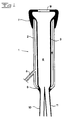
- Fig 1 shows a first embodiment with a teatcup 1 which comprises a teatcup shell 2 and a teatcup liner 3 which is disposed in the teatcup shell 2 in such a way that a pulsation chamber 4 is formed between the teatcup liner 3 and the teatcup shell 2.
- the pulsation chamber 4 is, in a manner known per se, arranged to receive a cyclically alternating pressure level from a pulsator and a vacuum pump (not shown) via a pulse conduit 5.
- the pressure level may for example vary between atmospheric pressure and a sub-pressure of about 50 kPa. Consequently, the teatcup liner 3 will provide a pulsating movement in such a way that it cyclically expands and retracts.
- the teatcup liner 3 defines an inner space 6 and comprises an upper end portion 7 and a lower end portion 8. At the upper end portion 7 an inlet passage 9 is arranged, which extends into the inner space 6 and through which a teat is intended to be insertable into the teatcup 1 and the inner space 6 of the teatcup liner 3.
- the lower end portion 8 of the teatcup liner 3 comprises two hose-like outlet portions or outlet conduits 10 and 11, each of which forms an outlet passage which extends from the inner space 6 and is arranged to discharge milk from the inner space 6.
- outlet conduits 10 and 11 may have a considerable length and for example extend all the way to a teatcup claw or any other milk collecting member (not shown), or be short and essentially only be constituted by an opening through the wall of the lower end portion 8 of the teatcup liner 3, wherein each of these openings is arranged to be connected to a separate conduit member.
- the teatcup liner 3, with said outlet passages and with or without the outlet conduits 10, 11 are advantageously manufactured of a single continuous piece of a rubber-like material.
- a first of the outlet conduits 10 may be arranged to discharge the foremilk, i.e. the first quantity of milk being received in connection with a milking operation, to a special collecting member for the latter and the second outlet conduit 11 may be arranged to discharge the main milk flow to the milk collecting member which usually constitute a part of a milking plant.
- the milk collecting member for the foremilk may also advantageously comprise equipment for analysing the quality of the milk, for example if it contains impermissibly high concentrations of bacteria or other micro-organisms.
- the outlet conduits 10 and 11 not necessarily need to have the same dimension, for example the outlet conduit 10 for the foremilk may have a smaller cross-sectional diameter than the outlet conduit 11 for the main milk flow.
- Means for example in the form of a valve device, may be provided either directly on the outlet conduits 10 and 11 or on conduits connectable to the latter in order to close ore open each of the outlet passages of the outlet conduits 10 and 11, respectively, in order to control the milk flow to either the one or the other outlet passage.
- valve devices will now be explained with reference to Figs 2 - 9. It is to be noted that components, which have substantially the same function in the different embodiments, have been provided with the same reference signs. For the sake of simplicity the pulse conduit 5 have been omitted in Figs 2 - 4 and 6 - 9.
- Figs 2 - 4 show a second embodiment which differs from the first embodiment in that such a valve device mentioned above has been arranged in the inner space 6 at the lower end portion 8 of the teatcup liner 3.
- the valve device 12 comprises a valve which is arranged to be pivotable in an annular member 13 and which comprises two valve bodies 14 and 15, which are arranged to be able to abut a respective valve seat, which is formed by the outlet passage of the respective outlet conduit 10 and 11.
- the valve is shown in a rest position in which the two valve bodies 14 and 15 are located at substantially the same distance from the respective valve seat.
- the valve is arranged to take said rest position by means of a spring member not shown and be pivotable from the rest position against the action of a restoring spring force of the spring member.
- Fig 2 the valve is shown in one of two possible end positions, in which the valve body 14 abuts the valve seat of the outlet passage of the outlet conduit 10.
- the outlet passage of the outlet conduit 11 is open and milk may flow from the inner space 6 out through the outlet passage of the outlet conduit 11 to the milk collecting member. If the same pressure prevails in the inner space 6 and the outlet passages of the outlet conduits 10, 11 the valve will be positioned in the rest position shown in Fig 3. If a sub-pressure is generated in the outlet passage of the outlet conduit 10 the valve body 14 will be displaced to abutment against the valve seat of the outlet conduit 10 and consequently close this outlet passage.
- annular member 13 and the valve bodies 14, 15 of the valve device 12 form a unit which is insertable into the inner space 6 of the teatcup liner 3 through the inlet passage 9 to abutment against a stop member 16 in the form of an annular recess at the lower end portion 8.
- Fig 5 shows a third embodiment with a valve device which is arranged to cause a closing of the outlet passages of the outlet conduits 10, 11 by a compression of the outlet conduit 10, 11 in question.
- this compression of the outlet conduits 10, 11, which constitute a part of the teatcup liner 3, is provided but it is also possible to provide such a valve device 12 in the conduit portion, which is connected to a respective outlet passage of the teatcup liner 3.
- each of the outlet conduits 10, 11 is enclosed in a chamber 17 and 18, respectively, which via connecting nipples 19, 20 are connected to means, which are arranged to generate a desirable pressure level in the respective chamber 17, 18.
- the part of the outlet conduit 10 which is located in the chamber 17 will be compressed or collapse in a way which corresponds the way in which a teatcup liner collapses during each pulsation cycle.
- the outlet passage of the outlet conduit 10 will be closed and thereby a milk flow is prevented from passing through this outlet passage.
- at least a part of the walls of the outlet conduits 10, 11 in respective chamber 17, 18 may, as is shown in Fig 5, be thinner in comparison with the walls of the outlet conduits 10, 11 outside the chambers 17, 18.
- the outlet conduits 10, 11 may be provided with surrounding beads 21 in the area where the outlet conduits 10, 11 pass through the walls of the chambers 17, 18 in order to provide a leak-proof seal around the outlet conduits 10, 11.
- Figs 6 and 7 shows a fourth embodiment in which the valve device 12 comprises a member with two parts, in the form of memory metal elements 22, one for each outlet conduit 10, 11.
- the memory metal elements 22 in the shown embodiment are designed as helical spring elements and abut with an outer end an inner wall of a chamber housing the memory metal elements 22.
- the chamber is formed by a collar-like extension of the teatcup shell 2.
- Each such memory metal element or helical spring element 22 comprises an electrical heating member 23, which according to the embodiment shown in Figs 6, 7 is centrally arranged in the helical spring element 22. By conducting a current through the heating member 23 an extension of the memory metal elements 22 may be provided in order to displace these in a direction towards each other and to compress the outlet conduit 10 and 11, respectively, located therebetween.
- the heating of the memory metal elements 22 also may be provided by conducting a current through the memory metal elements 22 themselves, i.e. the memory metal element 22 also form the heating members. Furthermore, it is also possible to replace the memory metal elements by other mechanical drive members, for example electromagnets.
- Figs 8 and 9 shows a fifth embodiment with a valve device 12 which comprises an one-way valve 24, 25 for each outlet passage.
- Each one-way valve 24, 25 is arranged to open the outlet passage in question when the pressure in the inner space 6 substantially exceeds the pressure in the outlet passage in question.
- the valve device 12 forms a unit which is insertable into the inner space 6 of the teatcup liner 3 to abutment against a stop member 16 at the lower end portion 8.
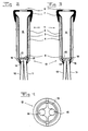
- Fig 10 shows a mould for the manufacture of the teatcup liner which is shown in Figs 1 - 8.
- the mould comprises a two-piece outer mould 30, only one part 30 of which is shown in Fig 10. However, it is to be noted that the two pieces 30 of the outer mould are substantially identical.
- the outer mould 30 forms a cavity which corresponds to the outer contour of the teatcup liner 3.
- the mould comprises a first core part 31 with an outer contour which corresponds to the inner contour of the inner space 6 of the teatcup liner 3.
- the mould comprises two further core parts 32, 33 which each corresponds to the inner contour of an outlet conduit 10 and 11, respectively.
- the two further core parts 32, 33 are connected to the first core part 31 by being insertable in a respective recess 34, 35 of the first core part 31.
- the mould comprises inlet members 36, schematically indicated, for injection of the rubber material of which the teatcup liner 3 is to be manufactured.
- a teatcup liner 3 is performed in such a manner that the mould is assembled, wherein the two further core parts 32, 33 are inserted in its respective recess 34, 35 in the first core part 31. Thereafter, the core parts are placed in the cavity in one piece of the outer mould 30 whereafter the other piece is applied. Thereafter, the rubber material is injected into the mould through the inlet members 36 and after a suitable time period the mould is pulled apart and the teatcup liner 3 is removed from the outer mould 30 and the core parts 31, 32, 33 by the first core part being pulled in a first direction and the two further core parts 32, 33 being pulled in a substantially opposite direction.
Landscapes
- Engineering & Computer Science (AREA)
- Mechanical Engineering (AREA)
- Life Sciences & Earth Sciences (AREA)
- Animal Husbandry (AREA)
- Environmental Sciences (AREA)
- Manufacturing & Machinery (AREA)
- External Artificial Organs (AREA)
- Check Valves (AREA)
- Casting Or Compression Moulding Of Plastics Or The Like (AREA)
- Magnetic Resonance Imaging Apparatus (AREA)
- Formation And Processing Of Food Products (AREA)
- Heating, Cooling, Or Curing Plastics Or The Like In General (AREA)
- Medical Preparation Storing Or Oral Administration Devices (AREA)
- Materials For Medical Uses (AREA)
- Moulds For Moulding Plastics Or The Like (AREA)
Applications Claiming Priority (3)
| Application Number | Priority Date | Filing Date | Title |
|---|---|---|---|
| SE9704791A SE9704791L (sv) | 1997-12-19 | 1997-12-19 | Spengummianordning med två utloppspassager samt gjutform och förfarande för tillverkning av anordningen |
| SE9704791 | 1997-12-19 | ||
| PCT/SE1998/002392 WO1999034664A1 (en) | 1997-12-19 | 1998-12-18 | A teatcup liner device |
Publications (2)
| Publication Number | Publication Date |
|---|---|
| EP1039798A1 EP1039798A1 (en) | 2000-10-04 |
| EP1039798B1 true EP1039798B1 (en) | 2003-04-09 |
Family
ID=20409497
Family Applications (1)
| Application Number | Title | Priority Date | Filing Date |
|---|---|---|---|
| EP98965922A Expired - Lifetime EP1039798B1 (en) | 1997-12-19 | 1998-12-18 | A teatcup liner device |
Country Status (10)
| Country | Link |
|---|---|
| EP (1) | EP1039798B1 (https=) |
| JP (1) | JP2002500023A (https=) |
| AT (1) | ATE236512T1 (https=) |
| AU (1) | AU2193499A (https=) |
| CA (1) | CA2314894C (https=) |
| DE (1) | DE69813293T2 (https=) |
| DK (1) | DK1039798T3 (https=) |
| IL (1) | IL136856A (https=) |
| SE (1) | SE9704791L (https=) |
| WO (1) | WO1999034664A1 (https=) |
Families Citing this family (5)
| Publication number | Priority date | Publication date | Assignee | Title |
|---|---|---|---|---|
| NL1014260C2 (nl) * | 2000-02-02 | 2001-08-03 | Lely Entpr Ag | Inrichting voor het detecteren van fysische afwijkingen in melk. |
| NL1019625C2 (nl) | 2001-12-20 | 2003-06-30 | Lely Entpr Ag | Inrichting en melkbeker voor het melken van dieren. |
| SE0203871D0 (sv) * | 2002-12-20 | 2002-12-20 | Delaval Holding Ab | Milking Devices |
| SE527446C2 (sv) * | 2004-06-10 | 2006-03-07 | Delaval Holding Ab | Mjölkningsanordningar |
| DE102007003480B4 (de) * | 2007-01-24 | 2008-11-13 | Jakob Maier | Verfahren und Vorrichtung zur Bearbeitung eines Zitzengummis während der Herstellung |
Family Cites Families (6)
| Publication number | Priority date | Publication date | Assignee | Title |
|---|---|---|---|---|
| US1249134A (en) * | 1916-10-10 | 1917-12-04 | Laval Separator Co De | Teat-cup for milking-machines. |
| US1896321A (en) * | 1930-01-10 | 1933-02-07 | Robert E Maes | Teatcup for milking machine |
| SE8201338L (sv) * | 1982-03-04 | 1983-09-05 | Alfa Laval Ab | Spenkopp for mjolkningsmaskin |
| NL8700249A (nl) * | 1987-02-02 | 1988-09-01 | Multinorm Bv | Werkwijze voor het reinigen van een tepel van een vrouwelijk dier, melkwerkwijze en beker ten gebruike bij bovengenoemde werkwijzen. |
| ATE199810T1 (de) * | 1991-11-22 | 2001-04-15 | Berthold Johannes The Dietrich | Melkvorrichtung und zitzenbecher für diese vorrichtung |
| EP1219167B1 (en) * | 1996-04-17 | 2009-06-17 | Maasland N.V. | A machine for milking animals, such as cows |
-
1997
- 1997-12-19 SE SE9704791A patent/SE9704791L/xx not_active IP Right Cessation
-
1998
- 1998-12-18 EP EP98965922A patent/EP1039798B1/en not_active Expired - Lifetime
- 1998-12-18 AT AT98965922T patent/ATE236512T1/de not_active IP Right Cessation
- 1998-12-18 DK DK98965922T patent/DK1039798T3/da active
- 1998-12-18 CA CA002314894A patent/CA2314894C/en not_active Expired - Fee Related
- 1998-12-18 AU AU21934/99A patent/AU2193499A/en not_active Abandoned
- 1998-12-18 IL IL13685698A patent/IL136856A/en not_active IP Right Cessation
- 1998-12-18 WO PCT/SE1998/002392 patent/WO1999034664A1/en not_active Ceased
- 1998-12-18 JP JP2000527136A patent/JP2002500023A/ja active Pending
- 1998-12-18 DE DE69813293T patent/DE69813293T2/de not_active Expired - Fee Related
Also Published As
| Publication number | Publication date |
|---|---|
| CA2314894C (en) | 2008-02-19 |
| DK1039798T3 (da) | 2003-05-26 |
| SE508783C2 (sv) | 1998-11-02 |
| IL136856A0 (en) | 2001-06-14 |
| SE9704791D0 (sv) | 1997-12-19 |
| ATE236512T1 (de) | 2003-04-15 |
| IL136856A (en) | 2004-08-31 |
| EP1039798A1 (en) | 2000-10-04 |
| SE9704791L (sv) | 1998-11-02 |
| WO1999034664A1 (en) | 1999-07-15 |
| DE69813293T2 (de) | 2004-01-22 |
| JP2002500023A (ja) | 2002-01-08 |
| CA2314894A1 (en) | 1999-07-15 |
| DE69813293D1 (de) | 2003-05-15 |
| AU2193499A (en) | 1999-07-26 |
Similar Documents
| Publication | Publication Date | Title |
|---|---|---|
| EP0593563B1 (en) | Milking system with positive pressure on thin liner | |
| US8627785B2 (en) | Mouthpiece-vented teat cup inflation | |
| EP1039798B1 (en) | A teatcup liner device | |
| US12178185B2 (en) | Short milk tube vent plug for a dairy animal milker unit | |
| US7634972B2 (en) | Milking cup liner | |
| US3900005A (en) | Milking machine | |
| US4034712A (en) | Pulsation system | |
| CN116347977A (zh) | 挤奶衬垫 | |
| RU2257707C1 (ru) | Двухрежимный доильный аппарат | |
| US3234906A (en) | Method of milking and a specific teat cup liner | |
| RU2269889C1 (ru) | Двухрежимный доильный аппарат | |
| RU236630U1 (ru) | Регулируемый электромагнитный пульсатор для попарного доения | |
| RU2782594C1 (ru) | Электромагнитный пульсатор доильного аппарата попарного действия | |
| RU218672U1 (ru) | Пульсатор доильного аппарата попарного действия с регулируемым числом пульсаций | |
| RU217447U1 (ru) | Электропульсатор доильного аппарата | |
| RU2072771C1 (ru) | Доильный стакан | |
| EP1321029A2 (en) | A device and a teat cup for milking animals | |
| JP2014502852A (ja) | 搾乳装置 | |
| US3236208A (en) | Milker pulsator with adjustable timer control means | |
| RU215147U1 (ru) | Электронный пульсатор доильного аппарата | |
| RU2726250C1 (ru) | Электромагнитный пульсатор доильного аппарата | |
| RU2447653C2 (ru) | Электропульсатор доильного аппарата | |
| CA2110507A1 (en) | Milking machine clawpiece | |
| CN119604188A (zh) | 包括挤奶单元和真空部件所在的壳体的挤奶装置 | |
| RU2444181C2 (ru) | Устройство для автоматического изменения вакуумметрического давления и отключения доильного аппарата |
Legal Events
| Date | Code | Title | Description |
|---|---|---|---|
| PUAI | Public reference made under article 153(3) epc to a published international application that has entered the european phase |
Free format text: ORIGINAL CODE: 0009012 |
|
| 17P | Request for examination filed |
Effective date: 20000616 |
|
| AK | Designated contracting states |
Kind code of ref document: A1 Designated state(s): AT BE CH CY DE DK ES FI FR GB GR IE IT LI LU MC NL PT SE |
|
| GRAH | Despatch of communication of intention to grant a patent |
Free format text: ORIGINAL CODE: EPIDOS IGRA |
|
| GRAH | Despatch of communication of intention to grant a patent |
Free format text: ORIGINAL CODE: EPIDOS IGRA |
|
| GRAA | (expected) grant |
Free format text: ORIGINAL CODE: 0009210 |
|
| AK | Designated contracting states |
Designated state(s): AT BE CH CY DE DK ES FI FR GB GR IE IT LI LU MC NL PT SE |
|
| PG25 | Lapsed in a contracting state [announced via postgrant information from national office to epo] |
Ref country code: LI Free format text: LAPSE BECAUSE OF FAILURE TO SUBMIT A TRANSLATION OF THE DESCRIPTION OR TO PAY THE FEE WITHIN THE PRESCRIBED TIME-LIMIT Effective date: 20030409 Ref country code: IT Free format text: LAPSE BECAUSE OF FAILURE TO SUBMIT A TRANSLATION OF THE DESCRIPTION OR TO PAY THE FEE WITHIN THE PRESCRIBED TIME-LIMIT;WARNING: LAPSES OF ITALIAN PATENTS WITH EFFECTIVE DATE BEFORE 2007 MAY HAVE OCCURRED AT ANY TIME BEFORE 2007. THE CORRECT EFFECTIVE DATE MAY BE DIFFERENT FROM THE ONE RECORDED. Effective date: 20030409 Ref country code: FR Free format text: LAPSE BECAUSE OF FAILURE TO SUBMIT A TRANSLATION OF THE DESCRIPTION OR TO PAY THE FEE WITHIN THE PRESCRIBED TIME-LIMIT Effective date: 20030409 Ref country code: CH Free format text: LAPSE BECAUSE OF FAILURE TO SUBMIT A TRANSLATION OF THE DESCRIPTION OR TO PAY THE FEE WITHIN THE PRESCRIBED TIME-LIMIT Effective date: 20030409 Ref country code: BE Free format text: LAPSE BECAUSE OF FAILURE TO SUBMIT A TRANSLATION OF THE DESCRIPTION OR TO PAY THE FEE WITHIN THE PRESCRIBED TIME-LIMIT Effective date: 20030409 Ref country code: AT Free format text: LAPSE BECAUSE OF FAILURE TO SUBMIT A TRANSLATION OF THE DESCRIPTION OR TO PAY THE FEE WITHIN THE PRESCRIBED TIME-LIMIT Effective date: 20030409 |
|
| REG | Reference to a national code |
Ref country code: GB Ref legal event code: FG4D |
|
| REG | Reference to a national code |
Ref country code: CH Ref legal event code: EP |
|
| REG | Reference to a national code |
Ref country code: IE Ref legal event code: FG4D |
|
| REG | Reference to a national code |
Ref country code: DK Ref legal event code: T3 |
|
| PG25 | Lapsed in a contracting state [announced via postgrant information from national office to epo] |
Ref country code: SE Free format text: LAPSE BECAUSE OF FAILURE TO SUBMIT A TRANSLATION OF THE DESCRIPTION OR TO PAY THE FEE WITHIN THE PRESCRIBED TIME-LIMIT Effective date: 20030709 Ref country code: PT Free format text: LAPSE BECAUSE OF FAILURE TO SUBMIT A TRANSLATION OF THE DESCRIPTION OR TO PAY THE FEE WITHIN THE PRESCRIBED TIME-LIMIT Effective date: 20030709 Ref country code: GR Free format text: LAPSE BECAUSE OF FAILURE TO SUBMIT A TRANSLATION OF THE DESCRIPTION OR TO PAY THE FEE WITHIN THE PRESCRIBED TIME-LIMIT Effective date: 20030709 |
|
| REG | Reference to a national code |
Ref country code: CH Ref legal event code: PL |
|
| PG25 | Lapsed in a contracting state [announced via postgrant information from national office to epo] |
Ref country code: ES Free format text: LAPSE BECAUSE OF FAILURE TO SUBMIT A TRANSLATION OF THE DESCRIPTION OR TO PAY THE FEE WITHIN THE PRESCRIBED TIME-LIMIT Effective date: 20031030 |
|
| PG25 | Lapsed in a contracting state [announced via postgrant information from national office to epo] |
Ref country code: LU Free format text: LAPSE BECAUSE OF NON-PAYMENT OF DUE FEES Effective date: 20031218 Ref country code: IE Free format text: LAPSE BECAUSE OF NON-PAYMENT OF DUE FEES Effective date: 20031218 Ref country code: CY Free format text: LAPSE BECAUSE OF FAILURE TO SUBMIT A TRANSLATION OF THE DESCRIPTION OR TO PAY THE FEE WITHIN THE PRESCRIBED TIME-LIMIT Effective date: 20031218 |
|
| PG25 | Lapsed in a contracting state [announced via postgrant information from national office to epo] |
Ref country code: MC Free format text: LAPSE BECAUSE OF NON-PAYMENT OF DUE FEES Effective date: 20031231 |
|
| PLBE | No opposition filed within time limit |
Free format text: ORIGINAL CODE: 0009261 |
|
| STAA | Information on the status of an ep patent application or granted ep patent |
Free format text: STATUS: NO OPPOSITION FILED WITHIN TIME LIMIT |
|
| EN | Fr: translation not filed | ||
| 26N | No opposition filed |
Effective date: 20040112 |
|
| REG | Reference to a national code |
Ref country code: IE Ref legal event code: MM4A |
|
| PGFP | Annual fee paid to national office [announced via postgrant information from national office to epo] |
Ref country code: NL Payment date: 20071223 Year of fee payment: 10 |
|
| PGFP | Annual fee paid to national office [announced via postgrant information from national office to epo] |
Ref country code: FI Payment date: 20071228 Year of fee payment: 10 |
|
| PGFP | Annual fee paid to national office [announced via postgrant information from national office to epo] |
Ref country code: GB Payment date: 20071227 Year of fee payment: 10 Ref country code: DK Payment date: 20071231 Year of fee payment: 10 |
|
| PGFP | Annual fee paid to national office [announced via postgrant information from national office to epo] |
Ref country code: DE Payment date: 20080131 Year of fee payment: 10 |
|
| PG25 | Lapsed in a contracting state [announced via postgrant information from national office to epo] |
Ref country code: FI Free format text: LAPSE BECAUSE OF NON-PAYMENT OF DUE FEES Effective date: 20081218 |
|
| REG | Reference to a national code |
Ref country code: DK Ref legal event code: EBP |
|
| GBPC | Gb: european patent ceased through non-payment of renewal fee |
Effective date: 20081218 |
|
| NLV4 | Nl: lapsed or anulled due to non-payment of the annual fee |
Effective date: 20090701 |
|
| PG25 | Lapsed in a contracting state [announced via postgrant information from national office to epo] |
Ref country code: DE Free format text: LAPSE BECAUSE OF NON-PAYMENT OF DUE FEES Effective date: 20090701 |
|
| PG25 | Lapsed in a contracting state [announced via postgrant information from national office to epo] |
Ref country code: NL Free format text: LAPSE BECAUSE OF NON-PAYMENT OF DUE FEES Effective date: 20090701 Ref country code: GB Free format text: LAPSE BECAUSE OF NON-PAYMENT OF DUE FEES Effective date: 20081218 |
|
| PG25 | Lapsed in a contracting state [announced via postgrant information from national office to epo] |
Ref country code: DK Free format text: LAPSE BECAUSE OF NON-PAYMENT OF DUE FEES Effective date: 20090105 |