EP1039158B1 - Palier linéaire à éléments roulants - Google Patents
Palier linéaire à éléments roulants Download PDFInfo
- Publication number
- EP1039158B1 EP1039158B1 EP00103615A EP00103615A EP1039158B1 EP 1039158 B1 EP1039158 B1 EP 1039158B1 EP 00103615 A EP00103615 A EP 00103615A EP 00103615 A EP00103615 A EP 00103615A EP 1039158 B1 EP1039158 B1 EP 1039158B1
- Authority
- EP
- European Patent Office
- Prior art keywords
- supporting
- bearing element
- deflection
- return channel
- holding plate
- Prior art date
- Legal status (The legal status is an assumption and is not a legal conclusion. Google has not performed a legal analysis and makes no representation as to the accuracy of the status listed.)
- Expired - Lifetime
Links
Images

Classifications
-
- F—MECHANICAL ENGINEERING; LIGHTING; HEATING; WEAPONS; BLASTING
- F16—ENGINEERING ELEMENTS AND UNITS; GENERAL MEASURES FOR PRODUCING AND MAINTAINING EFFECTIVE FUNCTIONING OF MACHINES OR INSTALLATIONS; THERMAL INSULATION IN GENERAL
- F16C—SHAFTS; FLEXIBLE SHAFTS; ELEMENTS OR CRANKSHAFT MECHANISMS; ROTARY BODIES OTHER THAN GEARING ELEMENTS; BEARINGS
- F16C29/00—Bearings for parts moving only linearly
- F16C29/04—Ball or roller bearings
- F16C29/06—Ball or roller bearings in which the rolling bodies circulate partly without carrying load
- F16C29/0633—Ball or roller bearings in which the rolling bodies circulate partly without carrying load with a bearing body defining a U-shaped carriage, i.e. surrounding a guide rail or track on three sides
- F16C29/0635—Ball or roller bearings in which the rolling bodies circulate partly without carrying load with a bearing body defining a U-shaped carriage, i.e. surrounding a guide rail or track on three sides whereby the return paths are provided as bores in a main body of the U-shaped carriage, e.g. the main body of the U-shaped carriage is a single part with end caps provided at each end
- F16C29/065—Ball or roller bearings in which the rolling bodies circulate partly without carrying load with a bearing body defining a U-shaped carriage, i.e. surrounding a guide rail or track on three sides whereby the return paths are provided as bores in a main body of the U-shaped carriage, e.g. the main body of the U-shaped carriage is a single part with end caps provided at each end with rollers
-
- F—MECHANICAL ENGINEERING; LIGHTING; HEATING; WEAPONS; BLASTING
- F16—ENGINEERING ELEMENTS AND UNITS; GENERAL MEASURES FOR PRODUCING AND MAINTAINING EFFECTIVE FUNCTIONING OF MACHINES OR INSTALLATIONS; THERMAL INSULATION IN GENERAL
- F16C—SHAFTS; FLEXIBLE SHAFTS; ELEMENTS OR CRANKSHAFT MECHANISMS; ROTARY BODIES OTHER THAN GEARING ELEMENTS; BEARINGS
- F16C29/00—Bearings for parts moving only linearly
- F16C29/08—Arrangements for covering or protecting the ways
- F16C29/084—Arrangements for covering or protecting the ways fixed to the carriage or bearing body movable along the guide rail or track
- F16C29/088—Seals extending in the longitudinal direction of the carriage or bearing body
-
- F—MECHANICAL ENGINEERING; LIGHTING; HEATING; WEAPONS; BLASTING
- F16—ENGINEERING ELEMENTS AND UNITS; GENERAL MEASURES FOR PRODUCING AND MAINTAINING EFFECTIVE FUNCTIONING OF MACHINES OR INSTALLATIONS; THERMAL INSULATION IN GENERAL
- F16C—SHAFTS; FLEXIBLE SHAFTS; ELEMENTS OR CRANKSHAFT MECHANISMS; ROTARY BODIES OTHER THAN GEARING ELEMENTS; BEARINGS
- F16C33/00—Parts of bearings; Special methods for making bearings or parts thereof
- F16C33/30—Parts of ball or roller bearings
- F16C33/66—Special parts or details in view of lubrication
- F16C33/6603—Special parts or details in view of lubrication with grease as lubricant
- F16C33/6622—Details of supply and/or removal of the grease, e.g. purging grease
-
- F—MECHANICAL ENGINEERING; LIGHTING; HEATING; WEAPONS; BLASTING
- F16—ENGINEERING ELEMENTS AND UNITS; GENERAL MEASURES FOR PRODUCING AND MAINTAINING EFFECTIVE FUNCTIONING OF MACHINES OR INSTALLATIONS; THERMAL INSULATION IN GENERAL
- F16C—SHAFTS; FLEXIBLE SHAFTS; ELEMENTS OR CRANKSHAFT MECHANISMS; ROTARY BODIES OTHER THAN GEARING ELEMENTS; BEARINGS
- F16C33/00—Parts of bearings; Special methods for making bearings or parts thereof
- F16C33/30—Parts of ball or roller bearings
- F16C33/66—Special parts or details in view of lubrication
- F16C33/6637—Special parts or details in view of lubrication with liquid lubricant
- F16C33/6659—Details of supply of the liquid to the bearing, e.g. passages or nozzles
Definitions
- the invention relates to a linear rolling bearing element for mounting on the running surface of a guide rail, with a carriage, which has a supporting body and a return channel for a WälzSystemumlauf each in a support body, which are connected via two frontally adjacent to the supporting body Umlenkkanäle, wherein in the support zone , the return channel and the deflection channels guide means are arranged from a polymeric material for the rolling elements, of which the guide means of the support zone and the return channel are designed in the form of a coating which is attached to the support body in a single operation by injection molding, wherein the deflection channels at least Partially formed by deflecting bodies, which are releasably secured in the areas of the two end faces of the support body.
- a linear roller bearing element of the aforementioned type which has head pieces, in which the deflecting bodies are arranged.
- the following operations are required during assembly: First, an alignment of the head piece must be performed on the support body, which is done by hand or in a device. Thereafter, a visual inspection or test by means of a gauge is required to determine whether a correct fit of the header has been achieved on the support body. This results in a large processing effort for the bearing element.
- the mounted on the two end faces of the support body head pieces of the bearing element its construction weight increase.
- the document US 4 983 048 A shows a linear rolling bearing element in which the supporting rolling elements are directly supported on the inner surface of a bore of the (metallic) supporting body, while channels for the returning rolling bodies are likewise formed by bores of the supporting body.
- a polymeric coating as a guide means of the support zone and the return channel does not have this camp.
- Receptacles for diverters are formed by frontal stepped holes of the (metallic) support body.
- the invention has for its object to provide a linear rolling bearing element of the type mentioned, for its production, the assembly and Storage costs and the installation and testing costs are reduced.
- a deflecting body is completely inserted into a receiving body formed in the support body, accessible from an end face, with the polymeric material of the coating, which forms the guide means of the support zone and the return channel, in addition, in each case a front-side support body approach is shaped, which encloses the receiving space for the deflecting body. In this way, end caps can be omitted.
- the required receiving space for the deflecting is created by a Verallem of the support body, which may be a steel component, and by a corresponding end-side machining of the support body.
- the application of the ejection technology makes it possible to form the deflection zone for the rolling elements in plastic within the space of the support body.
- the complete rolling element circulation is now in the supporting body.
- the receiving space can by means of a directly adjacent to the support body Abstreifers be closed.
- the scraper may each be formed by an inner support plate, an outer support plate, a sealing strip and a support plate, which are fastened together by means of screws to the support body, wherein the inner support plate is arranged directly adjacent to the front side of the support body sunk or recessed in the support body. In the case of the sunk arrangement results in a flush conclusion with the support body.
- the polymeric material of the coating which forms the guide means of the support zone and the return channel, in addition in each case to form a front-side support body approach, which encloses the receiving space for the deflecting body.
- the inner holding plate of the scraper may be supported on a bearing surface formed in the supporting body approach.
- the invention results in additional benefits to increase the crash safety of the carriage, an increase in the breaking strength of the carriage, the elimination of joints that were previously between the headers and the support body, which also the dirt insensitivity increased, and an increase in the building block.
- the overall space of the carriage remains unchanged.
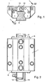
- An inventive bearing element shown in Figures 1 to 4 has a support body 1 with end-side receiving spaces 2.
- a deflecting body 3 is inserted, which causes the deflection of rolling elements 4 from a support area in a return region of the bearing element or from the return area in the support area.
- the bearing element is linearly movable along a guide rail 5.
- Each receiving space 2 is closed after insertion of the deflecting 3 at the respective end face of the support body 1 with a scraper 6, which ensures the stripping of impurities, such as metal chips, from the running surface 7 of the guide rail 5, on which formed as cylindrical rollers rolling elements. 4 roll.
- the scraper 6 also serves to seal the lubricated interior of the bearing member to the outside and includes an inner support plate 8, an outer support plate 9, a support plate 12 and a sealing strip 10.
- the supplied via the grease nipple lubricant passes through the lubricant channels 11 and through holes 15 of the inner plate 8 and through passageways 16 of the deflecting 3 to the rolling elements 4.
- the sealing of the passage bore 15 and the passageway 16 between the inner holding plate 8 and the deflecting 3 is performed with a sealing ring 17 which surrounds a passage 16 containing the nozzle.
- the support region and the return region for the rolling elements 4 are in the support body 1 of the bearing element in each case designed as a straight support zone 18 and parallel return channel 19 thereto. They are bounded by a coherent, the metallic material of the support body 1 surrounding coating 20 made of a polymeric material. This has with respect to the rolling elements 4 on radial guide surfaces 21 and 22 and axial guide surfaces.
- lubricant channels 23 and 24 are incorporated in the form of grooves which are open to the rolling elements 4 out.
- the lubricant channels 23 and 24 are located in the return channel 19 of the support body 1 and in a deflection channel 25 of the deflecting body 3 for the rolling elements 4. They are formed in a deflection path of the deflection body 3.
- the coating 20 extends not only to the return channels 19, but also to the support zone 18.
- the coating 20 in the form of guide webs for the rolling elements 4 is formed.
- the middle guide web 27 is connected in this way with the parts of the coating 20 in the two superposed return channels 19, as can be seen on the right side of Figure 4.
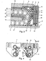
- the linear roller bearing element shown in Figure 5 is basically constructed as well, so that the same reference numerals have been used for the same components. It differs from the bearing element according to Figures 1 to 4, characterized in that the support body 31 is provided with end-side support body approaches 30. These are formed of the polymeric material, which also forms the coating 32 in the support zone 18, the return channel 19 and the deflection channel 25 at the same time.
- a support body extension 30 each contains a receiving space 33 for a deflecting body 34.
- the scraper 6 is arranged with the inner holding plate 8, the outer holding plate 9, the sealing strip 10 and the support plate 12 completely in the receiving space 33 and fastened with screws to the support body 31. In this case, the inner support plate 8 is supported on a contact surface 35, which is formed within the receiving space 33 on the supporting body approach 30.
Claims (5)
- Palier linéaire à éléments roulants pour l'appui sur la face de roulement d'un rail de guidage (5), avec un chariot de guidage qui comporte chaque fois dans un corps porteur (1, 31), pour une circulation des éléments roulants, une zone porteuse (18) et un canal de retour (19), qui sont reliés l'un à l'autre par deux canaux de déviation (25) à proximité du côté frontal sur le corps porteur (1, 31), dans lequel des moyens de guidage en un matériau polymère pour les éléments roulants (4) sont disposés dans la zone porteuse (18), le canal de retour (19) et les canaux de déviation (25), parmi lesquels les moyens de guidage de la zone porteuse (18) et du canal de retour (19) sont réalisés sous forme d'un revêtement (20, 32) qui est déposé en une seule opération par moulage par projection sur le corps porteur (1, 31), dans lequel les canaux de déviation (25) sont au moins en partie formés par des corps de déviation (3, 34) qui sont fixés de façon détachable dans les régions des deux faces frontales du corps porteur (1, 31), caractérisé en ce qu'un corps de déviation (3, 34) est chaque fois enfoncé entièrement dans un espace de réception (2, 33) formé dans le corps porteur (1, 31) et accessible par une face frontale, dans lequel, avec le matériau polymère du revêtement (20, 32), qui forme les moyens de guidage de la zone porteuse (18) et du canal de retour (19), on forme en outre chaque fois un bout frontal (30) du corps porteur qui entoure l'espace de réception (2, 33) pour le corps de déviation (3, 34).
- Palier selon la revendication 1, caractérisé en ce que l'espace de réception (2) est fermé vers l'extérieur au moyen d'un racloir (6) appliqué directement sur le corps porteur (1).
- Palier selon la revendication 1, caractérisé en ce qu'un racloir (6), avec lequel l'espace de réception (33) est fermé vers l'extérieur, est disposé dans l'espace de réception (33).
- Palier selon la revendication 2, caractérisé en ce que le racloir (6) est chaque fois formé d'une plaque de maintien interne (8), d'une plaque de maintien externe (9), d'une bande d'étanchéité (10) et d'une plaque de support (12), qui sont fixées ensemble au corps porteur (1) au moyen de vis (13), dans lequel la plaque de maintien interne (8) est disposée en application directe sur la face frontale du corps porteur (1).
- Palier selon la revendication 3, caractérisé en ce que le racloir (6) est chaque fois formé d'une plaque de maintien interne (8), d'une plaque de maintien externe (9), d'une bande d'étanchéité (10) et d'une plaque de support (12), qui sont fixées ensemble au corps porteur (31) au moyen de vis (13), dans lequel la plaque de maintien interne (8) est supportée sur une face d'appui (35) formée dans le bout de corps porteur (30).
Applications Claiming Priority (4)
| Application Number | Priority Date | Filing Date | Title |
|---|---|---|---|
| DE19913481 | 1999-03-25 | ||
| DE19913481 | 1999-03-25 | ||
| DE19923719A DE19923719A1 (de) | 1999-03-25 | 1999-05-22 | Linearwälzlagerelement |
| DE19923719 | 1999-05-22 |
Publications (3)
| Publication Number | Publication Date |
|---|---|
| EP1039158A2 EP1039158A2 (fr) | 2000-09-27 |
| EP1039158A3 EP1039158A3 (fr) | 2001-08-16 |
| EP1039158B1 true EP1039158B1 (fr) | 2006-04-19 |
Family
ID=26052578
Family Applications (1)
| Application Number | Title | Priority Date | Filing Date |
|---|---|---|---|
| EP00103615A Expired - Lifetime EP1039158B1 (fr) | 1999-03-25 | 2000-02-21 | Palier linéaire à éléments roulants |
Country Status (5)
| Country | Link |
|---|---|
| US (1) | US6318895B1 (fr) |
| EP (1) | EP1039158B1 (fr) |
| JP (1) | JP4541486B2 (fr) |
| DE (1) | DE50012589D1 (fr) |
| ES (1) | ES2259948T3 (fr) |
Families Citing this family (6)
| Publication number | Priority date | Publication date | Assignee | Title |
|---|---|---|---|---|
| JP4384379B2 (ja) * | 2001-09-20 | 2009-12-16 | 日本トムソン株式会社 | 方向転換路とリターン路とを接続管部で連通した直動案内ユニット |
| DE102004035211A1 (de) * | 2004-07-21 | 2006-02-16 | Ina-Schaeffler Kg | Linearführungseinheit |
| CN102434585B (zh) * | 2011-11-10 | 2014-10-29 | 宁波恒力汽配轴承有限公司 | 一种直线轴承滑动机构 |
| CN102491219B (zh) * | 2011-11-10 | 2015-07-22 | 宁波恒力汽配轴承有限公司 | 一种基于直线轴承的升降装置 |
| JP6384083B2 (ja) * | 2013-03-27 | 2018-09-05 | 日本精工株式会社 | リニアガイド装置用給油装置、リニアガイド装置 |
| CN111720436B (zh) * | 2019-03-21 | 2021-09-07 | 上银科技股份有限公司 | 线性滑轨 |
Family Cites Families (21)
| Publication number | Priority date | Publication date | Assignee | Title |
|---|---|---|---|---|
| DE1961468A1 (de) * | 1969-12-08 | 1971-06-16 | Georg Titt | Waelz-Laengslager |
| DE2632537C3 (de) * | 1976-07-20 | 1979-03-22 | Eberhard Hoeckle Gmbh, 7000 Stuttgart | Gelenkwelle mit teleskopartig ineinatiderverschiebbaren Wellenteilen |
| US4293166A (en) * | 1977-08-23 | 1981-10-06 | Skf Kugellagerfabriken Gmbh | Rolling bearing for relative linear movement on a shaft |
| US4390215A (en) | 1981-04-10 | 1983-06-28 | Nippon Thompson Co., Ltd. | Ball bearing slide unit for linear motion |
| JPS58622A (ja) | 1981-06-20 | 1983-01-05 | Minoru Suda | 摺動台用ベアリング装置 |
| JPS59147918U (ja) * | 1983-03-25 | 1984-10-03 | 日本精工株式会社 | リニアガイド装置 |
| DE3313129A1 (de) | 1983-04-12 | 1984-10-18 | Neff Gewindespindeln | Linearlageranordnung zur geradlinigen fuehrung eines schlittens laengs einer fuehrungsschiene |
| DE3911500A1 (de) * | 1989-04-08 | 1990-10-11 | Werner Jacob | Kugelumlaufbuechse fuer eine linearkugelfuehrung |
| DE3937781A1 (de) * | 1989-04-08 | 1990-10-11 | Werner Dipl Ing Jacob | Kugelumlaufeinheit fuer eine linearkugelfuehrung |
| DE4331014C2 (de) * | 1993-08-12 | 1997-09-04 | Schaeffler Waelzlager Kg | Linearwälzlagerelement |
| FR2714942B1 (fr) * | 1994-01-12 | 1996-04-05 | Bernard Guy Rene Rousseau | Ensemble de guidage, notamment pour outil de découpe. |
| JP3412914B2 (ja) * | 1994-05-20 | 2003-06-03 | Thk株式会社 | 転がり案内装置および転がり案内装置の移動ブロックの製造方法 |
| US5755516A (en) * | 1994-05-20 | 1998-05-26 | Thk Co., Ltd. | Rolling guide apparatus and method of manufacturing movable block of rolling guide apparatus |
| JP3314549B2 (ja) * | 1994-09-22 | 2002-08-12 | 日本精工株式会社 | リニアガイド装置のボール保持器 |
| JP3481771B2 (ja) * | 1996-04-25 | 2003-12-22 | Thk株式会社 | 直線案内装置のスライダの製造方法 |
| JP3954133B2 (ja) * | 1996-05-01 | 2007-08-08 | Thk株式会社 | 転がり案内装置の移動ブロックの製造方法 |
| JPH1047344A (ja) * | 1996-05-01 | 1998-02-17 | Thk Kk | 転がり運動案内装置 |
| JP3296716B2 (ja) * | 1996-05-02 | 2002-07-02 | テイエチケー株式会社 | 転がり運動案内装置および転がり運動案内装置の移動部材の製造方法 |
| JPH09296821A (ja) * | 1996-05-07 | 1997-11-18 | Thk Kk | 直線案内装置のスライダの製造方法 |
| JPH102332A (ja) * | 1996-06-18 | 1998-01-06 | Thk Kk | 複列ボールチェインを備えた直線運動案内装置 |
| DE19741626B4 (de) * | 1997-09-20 | 2008-03-27 | Skf Linearsysteme Gmbh | Kugellager für Längsbewegungen |
-
2000
- 2000-02-21 DE DE50012589T patent/DE50012589D1/de not_active Expired - Lifetime
- 2000-02-21 EP EP00103615A patent/EP1039158B1/fr not_active Expired - Lifetime
- 2000-02-21 ES ES00103615T patent/ES2259948T3/es not_active Expired - Lifetime
- 2000-03-22 JP JP2000080367A patent/JP4541486B2/ja not_active Expired - Fee Related
- 2000-03-24 US US09/535,918 patent/US6318895B1/en not_active Expired - Fee Related
Also Published As
| Publication number | Publication date |
|---|---|
| US6318895B1 (en) | 2001-11-20 |
| EP1039158A2 (fr) | 2000-09-27 |
| ES2259948T3 (es) | 2006-11-01 |
| JP2000291654A (ja) | 2000-10-20 |
| DE50012589D1 (de) | 2006-05-24 |
| EP1039158A3 (fr) | 2001-08-16 |
| JP4541486B2 (ja) | 2010-09-08 |
Similar Documents
| Publication | Publication Date | Title |
|---|---|---|
| EP0472167B1 (fr) | Palier à contact de roulement pour mouvement linéaire, soit des rouleaux guidés sur rails | |
| EP0670970B1 (fr) | Element de roulement lineaire | |
| EP2952761B1 (fr) | Chariot de guidage doté d'alésage de fixation faisant partie d'un passage d'écoulement de lubrifiant | |
| DE112008002621B4 (de) | Rollvorrichtung | |
| DE10145322A1 (de) | Lageranordnung für Zylinder, Walzen oder Trommeln | |
| DE3931806C2 (de) | Lineare Führungsvorrichtung | |
| EP3426938B1 (fr) | Guidage lineaire | |
| CH688386A5 (de) | Linearwaelzlagerelement. | |
| DE102010019681A1 (de) | Linearbewegungsvorrichtung mit Omega-Antrieb | |
| EP1247596A2 (fr) | Dispositif de guidage pour machine-outils | |
| EP1262673B1 (fr) | Palier à roulement linéaire | |
| DE19815525A1 (de) | Linearführung mit zwangsgeführtem Käfig | |
| EP1039158B1 (fr) | Palier linéaire à éléments roulants | |
| DE19956296B4 (de) | Linearführungsvorrichtung | |
| DE19815526B4 (de) | Linearführung mit Zwangsführung des Käfigs | |
| DE102019213988A1 (de) | Lagerkäfig, insbesondere Axiallagerkäfig | |
| DE19923719A1 (de) | Linearwälzlagerelement | |
| DE19741626B4 (de) | Kugellager für Längsbewegungen | |
| DE4438566B4 (de) | Linearwälzlager | |
| DE102019212497A1 (de) | Führungswagen für eine Linearführung | |
| DE10123268A1 (de) | Schnellspann-Einrichtung mit vereinfachtem Aufbau | |
| EP1113954B1 (fr) | Systeme pour permettre l'appui d'une caisse sur un chassis | |
| EP0418875B1 (fr) | Guidage linéaire avec des évidements pour l'assemblage | |
| DE19821329B4 (de) | Linearwälzlager | |
| EP1303706B1 (fr) | Roulement lineaire |
Legal Events
| Date | Code | Title | Description |
|---|---|---|---|
| PUAI | Public reference made under article 153(3) epc to a published international application that has entered the european phase |
Free format text: ORIGINAL CODE: 0009012 |
|
| 17P | Request for examination filed |
Effective date: 20000221 |
|
| AK | Designated contracting states |
Kind code of ref document: A2 Designated state(s): CH DE ES FR GB IT LI |
|
| AX | Request for extension of the european patent |
Free format text: AL;LT;LV;MK;RO;SI |
|
| PUAL | Search report despatched |
Free format text: ORIGINAL CODE: 0009013 |
|
| AK | Designated contracting states |
Kind code of ref document: A3 Designated state(s): AT BE CH CY DE DK ES FI FR GB GR IE IT LI LU MC NL PT SE |
|
| AX | Request for extension of the european patent |
Free format text: AL;LT;LV;MK;RO;SI |
|
| RIC1 | Information provided on ipc code assigned before grant |
Free format text: 7F 16C 29/06 A, 7F 16C 29/08 B |
|
| AKX | Designation fees paid |
Free format text: CH DE ES FR GB IT LI |
|
| RAP1 | Party data changed (applicant data changed or rights of an application transferred) |
Owner name: INA-SCHAEFFLER KG |
|
| 17Q | First examination report despatched |
Effective date: 20040415 |
|
| GRAP | Despatch of communication of intention to grant a patent |
Free format text: ORIGINAL CODE: EPIDOSNIGR1 |
|
| GRAS | Grant fee paid |
Free format text: ORIGINAL CODE: EPIDOSNIGR3 |
|
| GRAA | (expected) grant |
Free format text: ORIGINAL CODE: 0009210 |
|
| RAP1 | Party data changed (applicant data changed or rights of an application transferred) |
Owner name: SCHAEFFLER KG |
|
| AK | Designated contracting states |
Kind code of ref document: B1 Designated state(s): CH DE ES FR GB IT LI |
|
| PG25 | Lapsed in a contracting state [announced via postgrant information from national office to epo] |
Ref country code: IT Free format text: LAPSE BECAUSE OF FAILURE TO SUBMIT A TRANSLATION OF THE DESCRIPTION OR TO PAY THE FEE WITHIN THE PRESCRIBED TIME-LIMIT;WARNING: LAPSES OF ITALIAN PATENTS WITH EFFECTIVE DATE BEFORE 2007 MAY HAVE OCCURRED AT ANY TIME BEFORE 2007. THE CORRECT EFFECTIVE DATE MAY BE DIFFERENT FROM THE ONE RECORDED. Effective date: 20060419 |
|
| REG | Reference to a national code |
Ref country code: GB Ref legal event code: FG4D Free format text: NOT ENGLISH |
|
| REF | Corresponds to: |
Ref document number: 50012589 Country of ref document: DE Date of ref document: 20060524 Kind code of ref document: P |
|
| GBT | Gb: translation of ep patent filed (gb section 77(6)(a)/1977) |
Effective date: 20060809 |
|
| REG | Reference to a national code |
Ref country code: ES Ref legal event code: FG2A Ref document number: 2259948 Country of ref document: ES Kind code of ref document: T3 |
|
| ET | Fr: translation filed | ||
| PLBE | No opposition filed within time limit |
Free format text: ORIGINAL CODE: 0009261 |
|
| STAA | Information on the status of an ep patent application or granted ep patent |
Free format text: STATUS: NO OPPOSITION FILED WITHIN TIME LIMIT |
|
| 26N | No opposition filed |
Effective date: 20070122 |
|
| REG | Reference to a national code |
Ref country code: GB Ref legal event code: 732E Free format text: REGISTERED BETWEEN 20110407 AND 20110413 |
|
| REG | Reference to a national code |
Ref country code: DE Ref legal event code: R081 Ref document number: 50012589 Country of ref document: DE Owner name: SCHAEFFLER TECHNOLOGIES AG & CO. KG, DE Free format text: FORMER OWNER: SCHAEFFLER TECHNOLOGIES GMBH & CO. KG, 91074 HERZOGENAURACH, DE Effective date: 20120828 Ref country code: DE Ref legal event code: R081 Ref document number: 50012589 Country of ref document: DE Owner name: SCHAEFFLER TECHNOLOGIES GMBH & CO. KG, DE Free format text: FORMER OWNER: SCHAEFFLER TECHNOLOGIES GMBH & CO. KG, 91074 HERZOGENAURACH, DE Effective date: 20120828 |
|
| REG | Reference to a national code |
Ref country code: ES Ref legal event code: PC2A Owner name: SCHAEFFLER TECHNOLOGIES AG & CO.KG Effective date: 20130617 |
|
| REG | Reference to a national code |
Ref country code: CH Ref legal event code: PFA Owner name: SCHAEFFLER TECHNOLOGIES AG AND CO. KG, DE Free format text: FORMER OWNER: SCHAEFFLER KG, DE |
|
| REG | Reference to a national code |
Ref country code: DE Ref legal event code: R081 Ref document number: 50012589 Country of ref document: DE Owner name: SCHAEFFLER TECHNOLOGIES GMBH & CO. KG, DE Free format text: FORMER OWNER: SCHAEFFLER TECHNOLOGIES AG & CO. KG, 91074 HERZOGENAURACH, DE Effective date: 20140212 Ref country code: DE Ref legal event code: R081 Ref document number: 50012589 Country of ref document: DE Owner name: SCHAEFFLER TECHNOLOGIES AG & CO. KG, DE Free format text: FORMER OWNER: SCHAEFFLER TECHNOLOGIES AG & CO. KG, 91074 HERZOGENAURACH, DE Effective date: 20140212 |
|
| REG | Reference to a national code |
Ref country code: CH Ref legal event code: PFUS Owner name: SCHAEFFLER TECHNOLOGIES GMBH AND CO. KG, DE Free format text: FORMER OWNER: SCHAEFFLER TECHNOLOGIES AG AND CO. KG, DE |
|
| REG | Reference to a national code |
Ref country code: DE Ref legal event code: R081 Ref document number: 50012589 Country of ref document: DE Owner name: SCHAEFFLER TECHNOLOGIES AG & CO. KG, DE Free format text: FORMER OWNER: SCHAEFFLER TECHNOLOGIES GMBH & CO. KG, 91074 HERZOGENAURACH, DE Effective date: 20150127 |
|
| REG | Reference to a national code |
Ref country code: CH Ref legal event code: PFA Owner name: SCHAEFFLER TECHNOLOGIES AG AND CO. KG, DE Free format text: FORMER OWNER: SCHAEFFLER TECHNOLOGIES GMBH AND CO. KG, DE |
|
| REG | Reference to a national code |
Ref country code: ES Ref legal event code: PC2A Owner name: SCHAEFFLER TECHNOLOGIES AG & CO.KG Effective date: 20150512 |
|
| REG | Reference to a national code |
Ref country code: FR Ref legal event code: PLFP Year of fee payment: 17 |
|
| REG | Reference to a national code |
Ref country code: FR Ref legal event code: PLFP Year of fee payment: 18 |
|
| PGFP | Annual fee paid to national office [announced via postgrant information from national office to epo] |
Ref country code: CH Payment date: 20170224 Year of fee payment: 18 Ref country code: FR Payment date: 20170227 Year of fee payment: 18 |
|
| PGFP | Annual fee paid to national office [announced via postgrant information from national office to epo] |
Ref country code: GB Payment date: 20170228 Year of fee payment: 18 |
|
| PGFP | Annual fee paid to national office [announced via postgrant information from national office to epo] |
Ref country code: IT Payment date: 20170221 Year of fee payment: 18 |
|
| PGFP | Annual fee paid to national office [announced via postgrant information from national office to epo] |
Ref country code: ES Payment date: 20170331 Year of fee payment: 18 |
|
| PGFP | Annual fee paid to national office [announced via postgrant information from national office to epo] |
Ref country code: DE Payment date: 20180430 Year of fee payment: 19 |
|
| REG | Reference to a national code |
Ref country code: CH Ref legal event code: PL |
|
| GBPC | Gb: european patent ceased through non-payment of renewal fee |
Effective date: 20180221 |
|
| PG25 | Lapsed in a contracting state [announced via postgrant information from national office to epo] |
Ref country code: CH Free format text: LAPSE BECAUSE OF NON-PAYMENT OF DUE FEES Effective date: 20180228 Ref country code: LI Free format text: LAPSE BECAUSE OF NON-PAYMENT OF DUE FEES Effective date: 20180228 |
|
| REG | Reference to a national code |
Ref country code: FR Ref legal event code: ST Effective date: 20181031 |
|
| PG25 | Lapsed in a contracting state [announced via postgrant information from national office to epo] |
Ref country code: FR Free format text: LAPSE BECAUSE OF NON-PAYMENT OF DUE FEES Effective date: 20180228 Ref country code: GB Free format text: LAPSE BECAUSE OF NON-PAYMENT OF DUE FEES Effective date: 20180221 Ref country code: IT Free format text: LAPSE BECAUSE OF NON-PAYMENT OF DUE FEES Effective date: 20180221 |
|
| REG | Reference to a national code |
Ref country code: ES Ref legal event code: FD2A Effective date: 20190801 |
|
| REG | Reference to a national code |
Ref country code: DE Ref legal event code: R119 Ref document number: 50012589 Country of ref document: DE |
|
| PG25 | Lapsed in a contracting state [announced via postgrant information from national office to epo] |
Ref country code: ES Free format text: LAPSE BECAUSE OF NON-PAYMENT OF DUE FEES Effective date: 20180222 |
|
| PG25 | Lapsed in a contracting state [announced via postgrant information from national office to epo] |
Ref country code: DE Free format text: LAPSE BECAUSE OF NON-PAYMENT OF DUE FEES Effective date: 20190903 |
|
| P01 | Opt-out of the competence of the unified patent court (upc) registered |
Effective date: 20230522 |