EP1038611A2 - Laterne zum Befestigen eines Motors an einer Pumpe - Google Patents
Laterne zum Befestigen eines Motors an einer Pumpe Download PDFInfo
- Publication number
- EP1038611A2 EP1038611A2 EP00104074A EP00104074A EP1038611A2 EP 1038611 A2 EP1038611 A2 EP 1038611A2 EP 00104074 A EP00104074 A EP 00104074A EP 00104074 A EP00104074 A EP 00104074A EP 1038611 A2 EP1038611 A2 EP 1038611A2
- Authority
- EP
- European Patent Office
- Prior art keywords
- flange
- lantern
- connecting webs
- recesses
- pump
- Prior art date
- Legal status (The legal status is an assumption and is not a legal conclusion. Google has not performed a legal analysis and makes no representation as to the accuracy of the status listed.)
- Granted
Links
- 230000008878 coupling Effects 0.000 title 1
- 238000010168 coupling process Methods 0.000 title 1
- 238000005859 coupling reaction Methods 0.000 title 1
- 238000005266 casting Methods 0.000 claims description 4
- 229910001060 Gray iron Inorganic materials 0.000 claims description 2
- 238000004519 manufacturing process Methods 0.000 description 8
- 241001465382 Physalis alkekengi Species 0.000 description 6
- 238000000465 moulding Methods 0.000 description 6
- 230000015572 biosynthetic process Effects 0.000 description 2
- 239000000463 material Substances 0.000 description 2
- 238000010276 construction Methods 0.000 description 1
Images


Classifications
-
- B—PERFORMING OPERATIONS; TRANSPORTING
- B22—CASTING; POWDER METALLURGY
- B22C—FOUNDRY MOULDING
- B22C9/00—Moulds or cores; Moulding processes
- B22C9/22—Moulds for peculiarly-shaped castings
- B22C9/24—Moulds for peculiarly-shaped castings for hollow articles
-
- F—MECHANICAL ENGINEERING; LIGHTING; HEATING; WEAPONS; BLASTING
- F04—POSITIVE - DISPLACEMENT MACHINES FOR LIQUIDS; PUMPS FOR LIQUIDS OR ELASTIC FLUIDS
- F04B—POSITIVE-DISPLACEMENT MACHINES FOR LIQUIDS; PUMPS
- F04B17/00—Pumps characterised by combination with, or adaptation to, specific driving engines or motors
- F04B17/03—Pumps characterised by combination with, or adaptation to, specific driving engines or motors driven by electric motors
-
- F—MECHANICAL ENGINEERING; LIGHTING; HEATING; WEAPONS; BLASTING
- F04—POSITIVE - DISPLACEMENT MACHINES FOR LIQUIDS; PUMPS FOR LIQUIDS OR ELASTIC FLUIDS
- F04C—ROTARY-PISTON, OR OSCILLATING-PISTON, POSITIVE-DISPLACEMENT MACHINES FOR LIQUIDS; ROTARY-PISTON, OR OSCILLATING-PISTON, POSITIVE-DISPLACEMENT PUMPS
- F04C11/00—Combinations of two or more machines or pumps, each being of rotary-piston or oscillating-piston type; Pumping installations
-
- F—MECHANICAL ENGINEERING; LIGHTING; HEATING; WEAPONS; BLASTING
- F04—POSITIVE - DISPLACEMENT MACHINES FOR LIQUIDS; PUMPS FOR LIQUIDS OR ELASTIC FLUIDS
- F04D—NON-POSITIVE-DISPLACEMENT PUMPS
- F04D13/00—Pumping installations or systems
- F04D13/02—Units comprising pumps and their driving means
- F04D13/021—Units comprising pumps and their driving means containing a coupling
-
- H—ELECTRICITY
- H02—GENERATION; CONVERSION OR DISTRIBUTION OF ELECTRIC POWER
- H02K—DYNAMO-ELECTRIC MACHINES
- H02K7/00—Arrangements for handling mechanical energy structurally associated with dynamo-electric machines, e.g. structural association with mechanical driving motors or auxiliary dynamo-electric machines
- H02K7/14—Structural association with mechanical loads, e.g. with hand-held machine tools or fans
Definitions
- the present invention relates to a lantern for Attach a motor to a pump with a first one Flange for attachment to the engine and with a second Flange for attachment to the pump and with at least two connecting bridges between the first and the second flange in the lateral surface of an imaginary Truncated cone.
- Such lanterns are generally known.
- the one pump driving motor is in a certain over a lantern Distance connected to the pump.
- the motor drive shaft occurs in the middle through openings in the two flanges Attachment to the motor or pump.
- the invention also relates to a device for producing a such lantern by pouring.
- the object of the invention is therefore a structurally simple and easy to use lantern of the type mentioned create the inexpensive to manufacture with great stability is.
- the object of the invention is also a constructive simple device for producing such a lantern to provide.
- this object is achieved by a lantern Claim 1 or by a device according to claim 4 solved.
- the first flange is one of the number number corresponding to the connecting webs from the inside has directed recesses, each over extend an angular range between two Connection webs lies, and that the second flange is one of the Number of connecting bridges corresponding number from to outside recesses, each extend over an angular range that each of the angular range corresponds to a connecting bridge.
- the first flange is one of the number number corresponding to the connecting webs from the inside has directed recesses, each over extend an angular range between two Connection webs lies
- the second flange is one of the Number of connecting bridges corresponding number from to outside recesses, each extend over an angular range that each of the angular range corresponds to a connecting bridge.
- the main advantage of such an inventive Training a lantern is that undercuts that the use of cores in the manufacture is required make, are not present.
- Such a lantern draws thus both by a simple construction as well through an inexpensive manufacturability.
- Through the Possibility of cores for the side openings of the Being able to do without a lantern can save costs by up to about 40% can be achieved, which is especially true for large ones Quantity is a big advantage.
- the handling of the The lantern according to the invention is designed in exactly the same way simple, as is the case with the previously known lanterns is.
- Connecting webs it when the first flange with the second flange over two to eight, in particular over four, Connecting webs is connected. Especially with four Connecting webs, which are also referred to as ribs a particularly high strength or dimensional stability of the Lantern even when the engine speed changes abruptly given.
- the lantern is off Made of gray cast iron.
- the training according to the invention is can also be used advantageously in other materials.
- Devices for making a lantern by casting have a first mold half, the one with the inner contour the inner core forming the lantern into an outer contour the second half of the lantern can be inserted is.
- first mold half the one with the inner contour the inner core forming the lantern into an outer contour the second half of the lantern can be inserted is.
- a particularly simple and therefore inexpensive device for Production of the lantern according to the invention by casting is characterized in that the inner core radially has externally directed projections, each over extend an angular range that corresponds to the angular range between two connecting bridges of the lantern corresponds and which, when inserted into one another, corresponds to two mold halves in appropriately designed recesses the second half of the mold.
- the recesses between two connecting bridges each of the lantern and the There will be recesses in the first flange of the lantern advantageously by the projections of the inner core molded. Because the first flange in the area of the recesses each has an inwardly open recess, the Inner core with its projections when the lantern is removed from the mold easily in the axial direction from the other Half of the mold are pulled out.
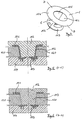
- the lantern shown in Figure 1 has a first flange 1, of the four connecting webs 2 with a second flange 3rd connected is.
- An electric motor not shown, is on the side of the first facing away from the second flange 3 Flange 1 attached, especially screwed.
- the motor shaft extends through an inner open Area of the first flange 1 and one in the middle of the second flange 3 provided opening 4.
- a pump not shown, is attached, in particular screwed, which is driven by the motor shaft.
- the first flange 1 has a larger outer diameter than the second flange 3.
- the connecting webs 2 are on the first Flange 1 attached to a larger diameter than that Diameter on which they open on the second flange 3.
- the individual connecting webs 2 therefore run obliquely on the Shell surface one between the first flange 1 and the second flange 3 imaginary truncated cone. Between each two connecting webs 2 there is an open area 5.
- the first flange 1 faces the one surrounding the inner opening Area four inward recesses 6 which each extend over the same angular sector, like an open area 5 between two connecting bars 2. Radially outside of the recesses 6 each formed only one web 7, at least one has approximately rectangular cross section 8. Between two webs 7 or between two recesses 6, an area 9 extends in the plane of the first Flange 1 radially inward, with at its inner end one connecting web 2 is connected.
- the second flange 3 has four outwards Recesses 10, each over the same Extend angular sector in which a connecting web 2nd runs. In the area of the open areas 5 between the The second flange 3 each has connecting webs 2 radially outward projection 11.
- Figures 2 and 3 show a device according to the invention for the manufacture of the lantern according to Figure 1. It has a first mold half 12, with its front region 16 the end face of the first flange 1 that is in contact with the motor as well as with a truncated cone-shaped inner core 13 Inner contour of the connecting webs 2 and that of the motor facing inner side of the second flange 3 forms.
- a second mold half 14 lies over an annular projection 15, which forms the outside of the first flange 1, on lower region 16 of the first mold half 12.
- the Inner contour of the second mold half 14 forms the outer sides the connecting webs 2 and the side facing the pump of the second flange 3.
- a central projection 17 is on the second mold half 14 provided to the opening 4 in Form second flange 3 of the lantern.
- FIG. 1 essentially shows only two Shaped elements 12 and 14, making the lanterns considerable can be produced more cost-effectively.
Landscapes
- Engineering & Computer Science (AREA)
- Mechanical Engineering (AREA)
- General Engineering & Computer Science (AREA)
- Power Engineering (AREA)
- Moulds For Moulding Plastics Or The Like (AREA)
- Rotary Pumps (AREA)
- Details And Applications Of Rotary Liquid Pumps (AREA)
- Structures Of Non-Positive Displacement Pumps (AREA)
Abstract
Description
- Figur 1:
- Dreidimensionale Ansicht einer erfindungsgemäßen Laterne.
- Figur 2:
- Querschnitt durch die Laterne und das Formwerkzeug entlang der Schnittebene A-A aus Figur 1.
- Figur 3:
- Querschnitt durch die Laterne und das Formwerkzeug entlang der Schnittebene B-B aus Figur 1.
- Figur 4:
- Dreidimensionale Ansicht einer aus dem Stand der Technik bekannten Laterne.
- Figur 5:
- Querschnitt durch die Laterne und das Formwerkzeug entlang der Schnittebene C-C aus Figur 4.
- Figur 6:
- Querschnitt durch die Laterne und das Formwerkzeug entlang der Schnittebene D-D aus Figur 4.
Claims (5)
- Laterne zum Befestigen eines Motors an einer Pumpe, mit einem ersten Flansch (1) zur Befestigung an dem Motor und mit einem zweiten Flansch (3) zur Befestigung an der Pumpe sowie mit mindestens zwei Verbindungsstegen (2), die zwischen dem ersten und dem zweiten Flansch (1, 3) in der Mantelfläche eines gedachten Kegelstumpfes verlauten, dadurch gekennzeichnet, daß der erste Flansch (1) eine der Anzahl der Verbindungsstege (2) entsprechende Anzahl von nach innen gerichteten Ausnehmungen (6) aufweist, die sich jeweils über einen Winkelbereich erstrecken, der zwischen jeweils zwei Verbindungsstegen (2) liegt, und daß der zweite Flansch (3) eine der Anzahl der Verbindungsstege (2) entsprechende Anzahl von nach außen gerichteten Ausnehmungen (10) aufweist, die sich jeweils über einen Winkelbereich erstrecken, über den sich ein Verbindungssteg (2) erstreckt.
- Laterne nach Anspruch 1, dadurch gekennzeichnet, daß der erste Flansch (1) mit dem zweiten Flansch (3) über zwei bis acht, insbesondere über vier Verbindungsstege (2) verbunden ist.
- Laterne nach Anspruch 1 oder 2, dadurch gekennzeichnet, daß sie aus Grauguß gefertigt ist.
- Vorrichtung zur Herstellung einer Laterne nach einem der vorherigen Ansprüche durch Gießen, mit einer ersten Formhälfte (12), die mit einem die Innenkontur der Laterne ausformenden Innenkern (13) in eine die Außenkontur der Laterne ausformende zweite Formhälfte (14) einschiebbar ist, dadurch gekennzeichnet, daß der Innenkern (13) radial nach außen gerichtete Vorsprünge (18) aufweist, die sich jeweils über einen Winkelbereich erstrecken, der dem Winkelbereich zwischen jeweils zwei Verbindungsstegen (2) der Laterne entspricht, und die im ineinander eingeschobenen Zustand der beiden Formhälften (12, 14) in entsprechend ausgebildeten Ausnehmungen (19) der zweiten Formhälfte einliegen.
- Vorrichtung nach Anspruch 4, dadurch gekennzeichnet, daß die Vorsprünge (18) des Innenkerns (13) die offenen Bereiche (5) zwischen jeweils zwei Verbindungsstegen (2) der Laterne und die Ausnehmungen (6) im ersten Flansch (1) der Laterne ausformen.
Applications Claiming Priority (2)
| Application Number | Priority Date | Filing Date | Title |
|---|---|---|---|
| DE19912936A DE19912936A1 (de) | 1999-03-22 | 1999-03-22 | Laterne zum Befestigen eines Motors an einer Pumpe |
| DE19912936 | 1999-03-22 |
Publications (3)
| Publication Number | Publication Date |
|---|---|
| EP1038611A2 true EP1038611A2 (de) | 2000-09-27 |
| EP1038611A3 EP1038611A3 (de) | 2001-09-12 |
| EP1038611B1 EP1038611B1 (de) | 2004-09-29 |
Family
ID=7901987
Family Applications (1)
| Application Number | Title | Priority Date | Filing Date |
|---|---|---|---|
| EP00104074A Expired - Lifetime EP1038611B1 (de) | 1999-03-22 | 2000-02-28 | Laterne zum Befestigen eines Motors an einer Pumpe |
Country Status (2)
| Country | Link |
|---|---|
| EP (1) | EP1038611B1 (de) |
| DE (2) | DE19912936A1 (de) |
Cited By (2)
| Publication number | Priority date | Publication date | Assignee | Title |
|---|---|---|---|---|
| WO2022079144A1 (de) | 2020-10-16 | 2022-04-21 | KSB SE & Co. KGaA | Laterne mit stegen |
| WO2022128287A1 (de) | 2020-12-16 | 2022-06-23 | KSB SE & Co. KGaA | Laterne mit elementen zur wärmeableitung |
Families Citing this family (2)
| Publication number | Priority date | Publication date | Assignee | Title |
|---|---|---|---|---|
| DE102004051639A1 (de) * | 2004-10-23 | 2006-04-27 | Bayerische Motoren Werke Ag | Vorrichtung zum Steuern eines automatisch schaltenden Getriebes |
| DE202009017115U1 (de) | 2009-12-18 | 2010-03-25 | Schwarz Elektromotoren Gmbh | Elektromotor sowie Anordnung |
Family Cites Families (3)
| Publication number | Priority date | Publication date | Assignee | Title |
|---|---|---|---|---|
| IT8022153V0 (it) * | 1980-06-30 | 1980-06-30 | Zeta Fluid Srl | Mezzi componibili perl'accoppiamento meccanico fra un motore d'azionamento ed una pompa idraulica. |
| DE8606067U1 (de) * | 1986-03-06 | 1986-06-26 | Kupplungstechnik Gmbh, 4440 Rheine | Tragelement für Maschinenaggregate |
| FR2644520A1 (fr) * | 1989-03-17 | 1990-09-21 | Cazaux Rotorflex Ste Nle Ets | Dispositif d'accouplement d'un moteur a une pompe |
-
1999
- 1999-03-22 DE DE19912936A patent/DE19912936A1/de not_active Withdrawn
-
2000
- 2000-02-28 EP EP00104074A patent/EP1038611B1/de not_active Expired - Lifetime
- 2000-02-28 DE DE50007955T patent/DE50007955D1/de not_active Expired - Lifetime
Non-Patent Citations (1)
| Title |
|---|
| None |
Cited By (9)
| Publication number | Priority date | Publication date | Assignee | Title |
|---|---|---|---|---|
| WO2022079144A1 (de) | 2020-10-16 | 2022-04-21 | KSB SE & Co. KGaA | Laterne mit stegen |
| DE102021005120A1 (de) | 2020-10-16 | 2022-04-21 | KSB SE & Co. KGaA | Laterne mit thermischer Trennwirkung |
| WO2022079147A1 (de) | 2020-10-16 | 2022-04-21 | KSB SE & Co. KGaA | Laterne mit thermischer trennwirkung |
| DE102021005123A1 (de) | 2020-10-16 | 2022-04-21 | KSB SE & Co. KGaA | Laterne mit Stegen |
| JP2023545203A (ja) * | 2020-10-16 | 2023-10-26 | カーエスベー ソシエタス ヨーロピア ウント コンパニー コマンディート ゲゼルシャフト アウフ アクチェン | 連結部片を有するカップリングユニット |
| US12270399B2 (en) | 2020-10-16 | 2025-04-08 | KSB SE & Co. KGaA | Coupling unit with connecting pieces |
| WO2022128287A1 (de) | 2020-12-16 | 2022-06-23 | KSB SE & Co. KGaA | Laterne mit elementen zur wärmeableitung |
| DE102020133832A1 (de) | 2020-12-16 | 2022-06-23 | KSB SE & Co. KGaA | Laterne mit Elementen zur Wärmeableitung |
| US12510098B2 (en) | 2020-12-16 | 2025-12-30 | KSB SE & Co. KGaA | Lanterns with elements for heat discharge |
Also Published As
| Publication number | Publication date |
|---|---|
| DE50007955D1 (de) | 2004-11-04 |
| DE19912936A1 (de) | 2000-09-28 |
| EP1038611B1 (de) | 2004-09-29 |
| EP1038611A3 (de) | 2001-09-12 |
Similar Documents
| Publication | Publication Date | Title |
|---|---|---|
| DE2046486C3 (de) | Schaufelrad für Lüfter | |
| EP0028323B1 (de) | Halteclip zur lösbaren Befestigung von Funktionselementen auf einer Trägerplatte mittels Gewindebolzen | |
| CH666427A5 (de) | Metallspritz-giessform. | |
| DE102008017276A1 (de) | Rotor für einen elektrischen Antriebsmotor eines Kältemittelkompressors | |
| DE102008026648A1 (de) | Rotor für einen elektronisch kommutierten Elektromotor, Verfahren zur Herstellung eines solchen Rotors sowie bei der Herstellung eines solchen Rotors verwendbares Zwischenprodukt | |
| DE2904384C2 (de) | Gehäuse für sich im wesentlichen axial erstreckende rotierende Maschinen, insbesondere für Elektromotoren und mehrstufige Pumpen | |
| EP0241659A1 (de) | Laufrad für eine Radialpumpe | |
| EP0153489A1 (de) | Mutterartiges Befestigungselement für Gewindebolzen | |
| DE69812678T2 (de) | Rotor mit permanentmagneten für einien elektromotor | |
| EP1038611B1 (de) | Laterne zum Befestigen eines Motors an einer Pumpe | |
| EP1133645A1 (de) | Spanlos umgeformter synchronring | |
| DE60006569T2 (de) | Lösbare befestigungsvorrichtung und -verfahren für laufradbefestigung auf eine welle eines hochgeschwindigkeitsverdichters | |
| EP0305702A1 (de) | Wärmetauscher mit einer Rippenrohranordnung | |
| EP4337870B1 (de) | Sicherungsmutter mit federspeicher-formkragen | |
| EP1503096A2 (de) | Halteelement zur Fixierung wenigstens eines Lagers | |
| DE3606953C2 (de) | Aufbereitungsvorrichtung für Druckluft od.dgl. | |
| EP1801459A1 (de) | Schaufel und Schaufelbaugruppe für den Stator eines Drehmomentwandlers, Stator mit Schaufeln für einen Drehmomentwandler, und Verfahren zu deren Herstellung | |
| EP0801458B1 (de) | Elektromotor | |
| DE2808332A1 (de) | Riemenscheibe | |
| EP4344848A1 (de) | Spritzgegossener hohlkörper, vorrichtung zum herstellen eines solchen und verstellbarer fluidverteiler mit einem solchen | |
| EP0830884A1 (de) | Bausatz zur Herstellung eines Spielzeugwürfels | |
| EP4039992B1 (de) | Verbindungsteil und verfahren zur herstellung eines verbindungteils | |
| EP0153633B1 (de) | Knotenpunktteil zur Verbindung einander benachbarter Bauteile | |
| DE102007062484B3 (de) | Druckgussöffnungen mit Vorsprüngen | |
| DE3942903C1 (de) |
Legal Events
| Date | Code | Title | Description |
|---|---|---|---|
| PUAI | Public reference made under article 153(3) epc to a published international application that has entered the european phase |
Free format text: ORIGINAL CODE: 0009012 |
|
| AK | Designated contracting states |
Kind code of ref document: A2 Designated state(s): AT BE CH CY DE DK ES FI FR GB GR IE IT LI LU MC NL PT SE Kind code of ref document: A2 Designated state(s): DE FR GB IT |
|
| AX | Request for extension of the european patent |
Free format text: AL;LT;LV;MK;RO;SI |
|
| PUAL | Search report despatched |
Free format text: ORIGINAL CODE: 0009013 |
|
| AK | Designated contracting states |
Kind code of ref document: A3 Designated state(s): AT BE CH CY DE DK ES FI FR GB GR IE IT LI LU MC NL PT SE |
|
| AX | Request for extension of the european patent |
Free format text: AL;LT;LV;MK;RO;SI |
|
| 17P | Request for examination filed |
Effective date: 20011010 |
|
| AKX | Designation fees paid |
Free format text: DE FR GB IT |
|
| GRAP | Despatch of communication of intention to grant a patent |
Free format text: ORIGINAL CODE: EPIDOSNIGR1 |
|
| GRAS | Grant fee paid |
Free format text: ORIGINAL CODE: EPIDOSNIGR3 |
|
| RAP1 | Party data changed (applicant data changed or rights of an application transferred) |
Owner name: WILO AG |
|
| GRAA | (expected) grant |
Free format text: ORIGINAL CODE: 0009210 |
|
| AK | Designated contracting states |
Kind code of ref document: B1 Designated state(s): DE FR GB IT |
|
| REG | Reference to a national code |
Ref country code: GB Ref legal event code: FG4D Free format text: NOT ENGLISH |
|
| REF | Corresponds to: |
Ref document number: 50007955 Country of ref document: DE Date of ref document: 20041104 Kind code of ref document: P |
|
| GBT | Gb: translation of ep patent filed (gb section 77(6)(a)/1977) |
Effective date: 20041203 |
|
| ET | Fr: translation filed | ||
| PLBE | No opposition filed within time limit |
Free format text: ORIGINAL CODE: 0009261 |
|
| STAA | Information on the status of an ep patent application or granted ep patent |
Free format text: STATUS: NO OPPOSITION FILED WITHIN TIME LIMIT |
|
| 26N | No opposition filed |
Effective date: 20050630 |
|
| REG | Reference to a national code |
Ref country code: FR Ref legal event code: PLFP Year of fee payment: 17 |
|
| REG | Reference to a national code |
Ref country code: FR Ref legal event code: PLFP Year of fee payment: 18 |
|
| PGFP | Annual fee paid to national office [announced via postgrant information from national office to epo] |
Ref country code: FR Payment date: 20170124 Year of fee payment: 18 |
|
| PGFP | Annual fee paid to national office [announced via postgrant information from national office to epo] |
Ref country code: GB Payment date: 20170124 Year of fee payment: 18 |
|
| PGFP | Annual fee paid to national office [announced via postgrant information from national office to epo] |
Ref country code: IT Payment date: 20170120 Year of fee payment: 18 |
|
| PGFP | Annual fee paid to national office [announced via postgrant information from national office to epo] |
Ref country code: DE Payment date: 20180122 Year of fee payment: 19 |
|
| GBPC | Gb: european patent ceased through non-payment of renewal fee |
Effective date: 20180228 |
|
| REG | Reference to a national code |
Ref country code: FR Ref legal event code: ST Effective date: 20181031 |
|
| PG25 | Lapsed in a contracting state [announced via postgrant information from national office to epo] |
Ref country code: GB Free format text: LAPSE BECAUSE OF NON-PAYMENT OF DUE FEES Effective date: 20180228 Ref country code: FR Free format text: LAPSE BECAUSE OF NON-PAYMENT OF DUE FEES Effective date: 20180228 Ref country code: IT Free format text: LAPSE BECAUSE OF NON-PAYMENT OF DUE FEES Effective date: 20180228 |
|
| REG | Reference to a national code |
Ref country code: DE Ref legal event code: R119 Ref document number: 50007955 Country of ref document: DE |
|
| PG25 | Lapsed in a contracting state [announced via postgrant information from national office to epo] |
Ref country code: DE Free format text: LAPSE BECAUSE OF NON-PAYMENT OF DUE FEES Effective date: 20190903 |