EP1035627A1 - Vorrichtung mit mehreren elektrischen Doppelschichtkondensatoren und Verfahren zur Einstellung der Kondensatorspannungen - Google Patents
Vorrichtung mit mehreren elektrischen Doppelschichtkondensatoren und Verfahren zur Einstellung der Kondensatorspannungen Download PDFInfo
- Publication number
- EP1035627A1 EP1035627A1 EP00104479A EP00104479A EP1035627A1 EP 1035627 A1 EP1035627 A1 EP 1035627A1 EP 00104479 A EP00104479 A EP 00104479A EP 00104479 A EP00104479 A EP 00104479A EP 1035627 A1 EP1035627 A1 EP 1035627A1
- Authority
- EP
- European Patent Office
- Prior art keywords
- voltage
- double layer
- electric double
- layer capacitors
- capacitors
- Prior art date
- Legal status (The legal status is an assumption and is not a legal conclusion. Google has not performed a legal analysis and makes no representation as to the accuracy of the status listed.)
- Granted
Links
Images


Classifications
-
- H—ELECTRICITY
- H02—GENERATION; CONVERSION OR DISTRIBUTION OF ELECTRIC POWER
- H02J—CIRCUIT ARRANGEMENTS OR SYSTEMS FOR SUPPLYING OR DISTRIBUTING ELECTRIC POWER; SYSTEMS FOR STORING ELECTRIC ENERGY
- H02J7/00—Circuit arrangements for charging or depolarising batteries or for supplying loads from batteries
- H02J7/0013—Circuit arrangements for charging or depolarising batteries or for supplying loads from batteries acting upon several batteries simultaneously or sequentially
- H02J7/0014—Circuits for equalisation of charge between batteries
- H02J7/0016—Circuits for equalisation of charge between batteries using shunting, discharge or bypass circuits
-
- B—PERFORMING OPERATIONS; TRANSPORTING
- B60—VEHICLES IN GENERAL
- B60L—PROPULSION OF ELECTRICALLY-PROPELLED VEHICLES; SUPPLYING ELECTRIC POWER FOR AUXILIARY EQUIPMENT OF ELECTRICALLY-PROPELLED VEHICLES; ELECTRODYNAMIC BRAKE SYSTEMS FOR VEHICLES IN GENERAL; MAGNETIC SUSPENSION OR LEVITATION FOR VEHICLES; MONITORING OPERATING VARIABLES OF ELECTRICALLY-PROPELLED VEHICLES; ELECTRIC SAFETY DEVICES FOR ELECTRICALLY-PROPELLED VEHICLES
- B60L58/00—Methods or circuit arrangements for monitoring or controlling batteries or fuel cells, specially adapted for electric vehicles
- B60L58/10—Methods or circuit arrangements for monitoring or controlling batteries or fuel cells, specially adapted for electric vehicles for monitoring or controlling batteries
- B60L58/18—Methods or circuit arrangements for monitoring or controlling batteries or fuel cells, specially adapted for electric vehicles for monitoring or controlling batteries of two or more battery modules
- B60L58/22—Balancing the charge of battery modules
-
- B—PERFORMING OPERATIONS; TRANSPORTING
- B60—VEHICLES IN GENERAL
- B60L—PROPULSION OF ELECTRICALLY-PROPELLED VEHICLES; SUPPLYING ELECTRIC POWER FOR AUXILIARY EQUIPMENT OF ELECTRICALLY-PROPELLED VEHICLES; ELECTRODYNAMIC BRAKE SYSTEMS FOR VEHICLES IN GENERAL; MAGNETIC SUSPENSION OR LEVITATION FOR VEHICLES; MONITORING OPERATING VARIABLES OF ELECTRICALLY-PROPELLED VEHICLES; ELECTRIC SAFETY DEVICES FOR ELECTRICALLY-PROPELLED VEHICLES
- B60L2200/00—Type of vehicles
- B60L2200/26—Rail vehicles
-
- B—PERFORMING OPERATIONS; TRANSPORTING
- B60—VEHICLES IN GENERAL
- B60L—PROPULSION OF ELECTRICALLY-PROPELLED VEHICLES; SUPPLYING ELECTRIC POWER FOR AUXILIARY EQUIPMENT OF ELECTRICALLY-PROPELLED VEHICLES; ELECTRODYNAMIC BRAKE SYSTEMS FOR VEHICLES IN GENERAL; MAGNETIC SUSPENSION OR LEVITATION FOR VEHICLES; MONITORING OPERATING VARIABLES OF ELECTRICALLY-PROPELLED VEHICLES; ELECTRIC SAFETY DEVICES FOR ELECTRICALLY-PROPELLED VEHICLES
- B60L2240/00—Control parameters of input or output; Target parameters
- B60L2240/40—Drive Train control parameters
- B60L2240/54—Drive Train control parameters related to batteries
- B60L2240/545—Temperature
-
- B—PERFORMING OPERATIONS; TRANSPORTING
- B60—VEHICLES IN GENERAL
- B60L—PROPULSION OF ELECTRICALLY-PROPELLED VEHICLES; SUPPLYING ELECTRIC POWER FOR AUXILIARY EQUIPMENT OF ELECTRICALLY-PROPELLED VEHICLES; ELECTRODYNAMIC BRAKE SYSTEMS FOR VEHICLES IN GENERAL; MAGNETIC SUSPENSION OR LEVITATION FOR VEHICLES; MONITORING OPERATING VARIABLES OF ELECTRICALLY-PROPELLED VEHICLES; ELECTRIC SAFETY DEVICES FOR ELECTRICALLY-PROPELLED VEHICLES
- B60L2240/00—Control parameters of input or output; Target parameters
- B60L2240/40—Drive Train control parameters
- B60L2240/54—Drive Train control parameters related to batteries
- B60L2240/547—Voltage
-
- B—PERFORMING OPERATIONS; TRANSPORTING
- B60—VEHICLES IN GENERAL
- B60L—PROPULSION OF ELECTRICALLY-PROPELLED VEHICLES; SUPPLYING ELECTRIC POWER FOR AUXILIARY EQUIPMENT OF ELECTRICALLY-PROPELLED VEHICLES; ELECTRODYNAMIC BRAKE SYSTEMS FOR VEHICLES IN GENERAL; MAGNETIC SUSPENSION OR LEVITATION FOR VEHICLES; MONITORING OPERATING VARIABLES OF ELECTRICALLY-PROPELLED VEHICLES; ELECTRIC SAFETY DEVICES FOR ELECTRICALLY-PROPELLED VEHICLES
- B60L2240/00—Control parameters of input or output; Target parameters
- B60L2240/40—Drive Train control parameters
- B60L2240/54—Drive Train control parameters related to batteries
- B60L2240/549—Current
-
- Y—GENERAL TAGGING OF NEW TECHNOLOGICAL DEVELOPMENTS; GENERAL TAGGING OF CROSS-SECTIONAL TECHNOLOGIES SPANNING OVER SEVERAL SECTIONS OF THE IPC; TECHNICAL SUBJECTS COVERED BY FORMER USPC CROSS-REFERENCE ART COLLECTIONS [XRACs] AND DIGESTS
- Y02—TECHNOLOGIES OR APPLICATIONS FOR MITIGATION OR ADAPTATION AGAINST CLIMATE CHANGE
- Y02T—CLIMATE CHANGE MITIGATION TECHNOLOGIES RELATED TO TRANSPORTATION
- Y02T10/00—Road transport of goods or passengers
- Y02T10/60—Other road transportation technologies with climate change mitigation effect
- Y02T10/70—Energy storage systems for electromobility, e.g. batteries
Definitions
- the present invention relates to an electric double layer capacitor apparatus or system including a plurality of electric double layer capacitors and a method for adjusting voltages of the plurality of electric double layer capacitors.
- Patent 5,932,932 (hereinafter referred to as the "'932 patent"), entitled “Storage battery voltage control apparatus”; and Japanese Unexamined Patent Publication (Kokai) 10-201091 (hereinafter referred to as the “'091 publication”), entitled “Power Supply Unit For Automotive Vehicle Utilizing Electric Double Layer Capacitors.”
- the contents of these applications are incorporated herein by reference in their entirety.
- an electric double layer capacitor apparatus includes a plurality of electric double layer capacitors 1 (hereinafter referred to as "a cell” or “cells"). Each cell 1 has a current bypass circuit 16 which is connected to each cell 1 in parallel.
- An operation voltage of the shunt regulator 7 is set at a maximum charge voltage (V u ) of the cell 1 by adjusting a ratio of resistance of the resistors (13 and 15).
- V u maximum charge voltage
- the shunt regulator 7 turns on and therefore current flows to the resistor 5.
- a PNP transistor 9 turns on and prevents all capacitors from being applied with voltages exceeding maximum charge voltage.
- the voltage between the positive and negative pole terminals (3A and 3B) is equal to the maximum charge voltage (V u ).
- Fig. 13 it is supposed that capacitance (C1) of the cell (1a) is 1000 (F), capacitance (C2) of the cell (1b) is 1150 (F) and charge current is constant at 10 (A). Further, initial voltages of the cells (1a and 1b) are equal to zero (V) and the maximum charge voltage (V u )is set at 2.5 (V) and equal to a uniform voltage.
- Heat of about 25 (W) generates in the bypass circuit (16) when bypass current flows for the period of ⁇ t.
- the '050 patent discloses a power supply unit which includes a plurality of electric double layer capacitors and a plurality of current bypass circuits which are connected to each cell in parallel, respectively. Each circuit has a Zener diode. The voltage of each cell is substantially adjusted to be Zener voltage.
- the '091 reference discloses a power source which includes a plurality of electric double layer capacitors and a plurality of discharge circuits in order to adjust the voltage of each cell.
- Each discharge circuit is connected to each cell in parallel via a switch. When an accessary switch of a car is turned on, each switch connects each discharge circuit to each cell. Accordingly, the voltage of each cell is adjusted.
- Each switch may be manually turned on to discharge each cell after an engine stops.
- the '932 reference discloses a storage battery voltage control apparatus which includes a plurality of electric double layer capacitors and a voltage-correcting storage battery over switches and a current-limiting resistor. In order to adjust the voltage of each cell, the voltages of each of the storage battery cells high in voltage can be equalized by transferring the charge to a storage battery cell low in voltage.
- an electric double layer capacitor apparatus or system includes a plurality of electric double layer capacitors connected in series, at least one set of a voltage detection device and a discharge device, and a controller.
- the at least one set is provided to at least one of the plurality of electric double layer capacitors.
- the voltage detection device is configured to detect a terminal voltage of the at least one of the plurality of electric double layer capacitors.
- the controller is configured to stop current for charging the plurality of electric double layer capacitors when the terminal voltage detected by the voltage detection device reaches a maximum charge voltage.
- the discharge device is configured to discharge the at least one of the plurality of electric double layer capacitors such that said terminal voltage drops toward a predetermined target voltage which is lower than the maximum charge voltage when the terminal voltage is higher than the predetermined target voltage, and the discharge device is configured not to discharge the at least one of the plurality of electric double layer capacitors when the terminal voltage is equal to or lower than the predetermined target voltage.
- a method for adjusting voltages of a plurality of electric double layer capacitors includes charging the plurality of electric double layer capacitors which are connected in series; detecting a terminal voltage of at least one of the plurality of electric double layer capacitors; stopping charging the plurality of electric double layer capacitors when it is determined that the terminal voltage is equal to or higher than a maximum charge voltage; discharging the at least one of the plurality of electric double layer capacitors such that the terminal voltage drops toward a predetermined target voltage which is lower than the maximum charge voltage when the terminal voltage is higher than the predetermined target voltage; and preventing discharging the at least one of the plurality of electric double layer capacitors such that the terminal voltage is maintained when the terminal voltage is equal to or lower than the predetermined target voltage.
- a voltage control circuit for an electric double layer capacitor apparatus which comprises a plurality of electric double layer capacitors connected in series, includes at least one voltage detection circuit, a controlling circuit, at least one electric discharging circuit.
- the least one voltage detection circuit is configured to detect a terminal voltage of at least one of the plurality of electric double layer capacitors.
- the controlling circuit is configured to stop charging the plurality of electric double layer capacitors when it is determined that voltage of at least one of the plurality of electric double layer capacitors is equal to or higher than a maximum charge voltage based on the detected terminal voltage.
- the at least one electric discharging circuit is provided corresponding to the at least one voltage detection circuit.
- the at least one electric discharging circuit is configured to discharge electricity charged in adjustment capacitors among the plurality of electric double layer capacitors such that voltage of each of the adjustment capacitors drops toward a predetermined target voltage which is lower than the maximum charge voltage when said terminal voltage is higher than the predetermined target voltage.
- a use of an electric double layer capacitors for a system includes a motor configured to operate the system, a plurality of electric double layer capacitors connected in series and configured to supply power to the motor, at least one set of a voltage detection device and a discharge device, and a controller.
- the at least one set is provided to at least one of the plurality of electric double layer capacitors.
- the voltage detection device is configured to detect a terminal voltage of the at least one of the plurality of electric double layer capacitors.
- the controller is configured to stop current for charging the plurality of electric double layer capacitors when the terminal voltage detected by the voltage detection device reaches a maximum charge voltage.
- the discharge device is configured to discharge the at least one of the plurality of electric double layer capacitors such that said terminal voltage drops toward a predetermined target voltage which is lower than the maximum charge voltage when the terminal voltage is higher than the predetermined target voltage, and the discharge device is configured not to discharge the at least one of the plurality of electric double layer capacitors when the terminal voltage is equal to or lower than the predetermined target voltage.
- an electric double layer capacitor apparatus 300 includes a plurality of electric double layer capacitors 1 (hereinafter referred to as "a cell” or “cells”), and a plurality sets of voltage detection circuit 50 and discharge circuit 60.
- the electric double layer capacitor apparatus 300 further includes positive and negative terminals (302 and 304) which are connected to a power supply source 306 via a switch 308.
- the power supply source 306 is a current supply source, preferably constant current source to the electric double layer capacitor apparatus 300 in order to charge the cells 1.
- the power supply source 306 may supply current which is adjustable or changeable as time elapses. Also the power supply source 306 is preferably to be a constant current source.
- Each voltage detection circuit 50 is connected to positive and negative ends of each of all cells 1 and detects voltage of each cell 1.
- voltage of any one of the cells 1 detected by a voltage detection circuit 50 is equal to or higher than a predetermined maximum charge voltage (V u ) of the cells 1, the voltage detection circuit 50 operates to open the switch 308. Accordingly, the power supply source 306 stops supplying electric power to the electric double layer capacitor apparatus 300.
- Each discharge circuit 60 is connected to the positive and negative ends of each of all cells 1.
- V e an equalized voltage which is lower than the maximum charge voltage (V u )
- V u the maximum charge voltage
- the discharge circuit 60 of that cell 1 is off and thus the cell 1 is not discharged through the discharge circuit 60.
- V e an equalized voltage
- V e the discharge circuit 60 of that cell 1 turns on and thus the cell 1 is discharged through the discharge circuit 60 such that the voltage of the cell 1 becomes substantially equal to the equalized voltage (V e ).
- the equalized voltage (V e ) is a predetermined target voltage.
- the discharge circuit 60 of that cell 1 when voltage of a cell 1 is higher than the equalized voltage (V e ), the discharge circuit 60 of that cell 1 turns on and thus the cell 1 is discharged even though during the charging period.
- the discharge circuit 60 may be off during the charging period even though voltage of a cell 1 is higher than the equalized voltage (V e ) and may turn on after the charging period is complete and when voltage of a cell 1 is higher than the equalized voltage (V e ).
- the maximum charge voltage (V u ) and the equalized voltage (V e ) may be semi-fixed values or automatically changeable values according to environments or applications.
- Fig. 2 illustrates changes of voltages (V a and V b ) of cells 1, for example, cells (1a and 1b). All cells 1 are not necessarily charged to have voltages higher than the equalized voltage (V e ). Referring to Figs. 1 and 2, both cells (1a and 1b) are charged during a charge period (t c ) from (T 0 ) to (T 2 ). At (T 2 ), the voltage (V a ) of the cell (1a) becomes equal to the maximum charge voltage (V u ). Accordingly, at (T 2 ), the voltage detection circuit 50 operates to open the switch 308 and the power supply source 306 stops supplying current the electric double layer capacitor apparatus 300.
- V drop R in * Ic, where Ic is charge current.
- the discharge circuit 60 of the cell (1a) turns on and thus the cell (1a) is discharged through the discharge circuit 60.
- the cell (1a) is a discharge capacitor.
- the cell (1a) is discharged during a discharge period (t D ) from (T 2 ) to (T 3 ).
- the discharge circuit 60 of the cell (1b) is off and thus the cell (1b) is not discharged through the discharge circuit 60.
- a load for example, a motor connected to the electric double layer capacitor apparatus 300 is turned on.
- the electric double layer capacitor apparatus 300 supplies power to the load.
- Both cells (1a and 1b) are again charged during a charge period (t c ) from (T 6 ) to (T 8 ). As this operation is repeated, voltages of all cells 1 are equalized at the equalized voltage (V e ) after being charged.
- Fig. 15 is a more detailed graph of the graph shown in Fig. 2. Table 1 explains each timing in Fig. 15.
- the voltage detection circuit 50 and the discharge circuit 60 may be constructed as an analog circuit utilizing transistors and other discrete parts. In this case, circuits which have stable operations may be obtained at low costs.
- the voltage detection circuit may outputs voltage or current signals which represent the detected voltage.
- the voltage detection circuit 50 and the discharging circuit 60 may be constructed to be an IC.
- Switching element of the discharge circuit is, for example, a transistor, another semiconductor or the like.
- the switching element When voltage of a cell 1 is higher than the equalized voltage (V e ), the switching element turns on to discharge the cell 1 via, for example, a resistor.
- V e When voltage of a cell 1 is equal to or lower than the equalized voltage (V e ), the switching element turns off and the cell 1 is not discharged.
- the discharge circuit 60 does not necessarily operate while the cells 1 are charged. Accordingly, a resistor to which discharge current flows may have large resistance. Therefore, since a discharge current value may be small, an amount of heat generation of the resistor and power loss may be small. However, the discharge period during which the voltage of a cell 1 becomes equal to the equalized voltage (V e ) becomes longer as the resistance of the resistor increases. Accordingly, the resistance of the resistor is determined by balancing the discharge period and the heat amount.
- the resistor may be a variable resistor.
- the charging and power supplying ability of the electric double layer capacitor apparatus may be fully utilized and the apparatus may stably operates for a long period of time. Even though characteristics of the electric double layer capacitors are different, the electric double layer capacitor apparatus may be efficiently charged and discharged by compensating the characteristics differences.
- the maximum charge voltage and the predetermined target voltage may be determined for each cell according to characteristics of each cell.
- the electric double layer capacitor apparatus 300 may include only one voltage detection circuit 50 and one discharge circuit 60 as shown in Fig. 3. Referring to Fig. 3, one voltage detection circuit 50 and one discharge circuit 60 are connected to, for example, two cells 1 which are connected in series.
- some of all cells 1 may have the voltage detection circuits 50 and one discharge circuits 60, respectively.
- the portion is selected from the group of cells who have smaller capacitance than the other, relatively. For example, in total cells with certain dispersion of capacitance, one half of smaller capacitance are arranged to be connected to the voltage detection circuits 50 and the discharge circuits 60 and the other half having higher capacitance may be open without the voltage detection circuits 50 and the discharge circuit 60.
- the electric double layer capacitor apparatus 300 may include only one voltage detection circuit 50 which detects the terminal voltage of each of the plurality of the cells 1 by switching the connection between the one voltage detection circuit 50 and each of the plurality of the cells 1.
- FIG. 5 shows an electric double layer capacitor apparatus according to an embodiment of the present invention.
- an electric double layer capacitor apparatus 300 includes a plurality of electric double layer capacitors 1. Since the plurality of cells 1 include same constructions, a circuit will be explained hereinafter with respect to a cell (1a).
- a terminal (27b) of a first shunt regulator 27 is connected to a positive pole terminal (3A) of the cell (1a). Another terminal (27a) of the first shunt regulator 27 is connected to a negative pole terminal (3B) of the cell (1a) via a resistor 25. Further, the terminal (27a) of the first shunt regulator 27 is connected to a base of a first NPN transistor 29. A terminal (27c) of the first shunt regulator 27 is connected to one end of a resistor 21 and one end of a resistor 23. Another end of the resistor 21 is connected to the positive pole terminal (3A) of the cell (1a). Another end of the resistor 23 is connected to the negative pole terminal (3B) of the cell (1a).
- An emitter of the first transistor 29 is connected to the negative pole terminal (3B) of the cell (1a).
- a collector of the first transistor 29 is connected to the positive pole terminal (3A) of the cell (1a) via a photocoupler 31.
- a terminal (37b) of a second shunt regulator 37 is connected to the positive pole terminal (3A) of the cell (1a). Another terminal (37a) of the second shunt regulator 37 is connected to the negative pole terminal (3B) of the cell (1a) via a resistor 35. Further, the terminal (37a) of the second shunt regulator 37 is connected to a base of a second NPN transistor 39. A terminal (37c) of the second shunt regulator 37 is connected to one end of a resistor 41 and one end of a resistor 43. Another end of the resistor 41 is connected to the positive pole terminal (3A) of the cell (1a) . Another end of the resistor 43 is connected to the negative pole terminal (3B) of the cell (1a).
- a collector of the second transistor 39 is connected to the positive pole terminal (3A) of the cell (1a).
- An emitter of the second transistor 39 is connected to the negative pole terminal (3B) of the cell (1a) via a resistor 45.
- the electric double layer capacitor apparatus 300 further includes positive and negative terminals (302 and 304) which are connected to a power supply source 306 via a switch 308.
- the switch 308 is controlled by the photocoupler 31.
- the power supply source 306 is configured to supply current to the electric double layer capacitor apparatus 300 in order to charge the cells 1.
- An operation voltage of the first shunt regulator 27 is set at the maximum charge voltage (V u ) of the cell 1.
- the operation voltage may be determined by adjusting a ratio of resistance of the resistors (21 and 23).
- the first shunt regulator 27 turns on and therefore current flows to the resistor 25.
- the first transistor 29 amplifies a signal which shows that the voltage between the positive and negative pole terminals (3A and 3B) is equal to or higher than the maximum charge voltage (V u ).
- the photocoupler 31 operates to open the switch 308. Accordingly, the power supply source 306 stops to supply electric power to the electric double layer capacitor apparatus 300.
- An operation voltage of the second shunt regulator 37 is set at the equalized voltage (V e ) which is lower than the maximum charge voltage (V u ).
- the equalized voltage (V e ) is determined based on a ratio of resistance of the resistors (41 and 43).
- the second shunt regulator 37 turns off and therefore the second transistor 39 turns off. Accordingly, the cell 1 maintains its voltage at that voltage.
- the second transistor 39 turns on even during the charging period of the cell 1 when the voltage between the positive and negative pole terminals (3A and 3B) is higher than the equalized voltage (V e ).
- the resistor 45 may have large resistance because the resistor 45 does not have a function of bypassing the cell 1 while cells 1 are charged. Accordingly, since the resistor 45 has large resistance, a power consumption of the resistor 45 is small. Therefore, there is no problem even though the second transistor 39 turns on during the charging period of the electric double layer capacitor 1.
- the circuit may be constructed such that the second transistor 39 does not turn on during the charging period of the cell 1 and turns on when the charging period is complete and when the voltage between the positive and negative pole terminals (3A and 3B) is higher than the equalized voltage (V e ).
- the charging and power supplying ability of the electric double layer capacitor apparatus may be fully utilized and the apparatus may stably operates for a long period of time. Even though characteristics of the electric double layer capacitors are different, the electric double layer capacitor apparatus may be efficiently charged and discharged by compensating the characteristics differences.
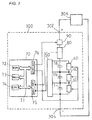
- an electric double layer capacitor apparatus 300 includes a plurality of electric double layer capacitors 1, discharge circuits 60 corresponding to respective cells 1, a voltage detection circuit 50, an electronic control unit 70, a current detection circuit 80, and a switching circuit 90.
- the electric double layer capacitor apparatus 300 further includes positive and negative terminals (302 and 304) which are connected to a power supply source 306.
- the power supply source 306 is configured to supply current to the electric double layer capacitor apparatus 300 in order to charge the cells 1.
- the electronic control unit 70 is constructed as a microprocessor and includes a ROM (read only memory) 72, a RAM (random access memory) 73, a CPU (micro-processor) 74, an input port 75, and an output port 76.
- the ROM 72, the RAM 73, the CPU 74, the input port 75, and the output port 76 are interconnected via a bidirectional bus 71.
- the discharge circuit 60 is configured to discharge the corresponding cell 1 and connected to the output port 76.
- the voltage detection circuit 50 is configured detect voltage of each cell 1 and connected to the input port 75.
- the current detection circuit 80 is configured detect the current of the electric double layer capacitor apparatus 300 and connected to the input port 75.
- the switching circuit 90 is configured to stop the power supply to the electric double layer capacitor apparatus 300 from the power supply source 306 and connected to the output port 76.
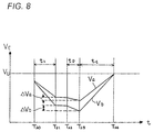
- Fig. 8 illustrates changes of voltages (V a and V b ) of cells 1, for example, cells (1a and 1b).
- the electric double layer capacitor apparatus 300 supplies power to the load. Accordingly, voltages of both cells (1a and 1b) decrease.
- voltage differences ( ⁇ V a and ⁇ V b ) are calculated such that the voltages (V a and V b ) of both cells (1a and 1b) become equal to the maximum charge voltage (V u ) substantially simultaneously while being charged.
- both cells (1a and 1b) are discharged such that each voltage (V a or V b ) reduce by the voltage difference ( ⁇ V a or ⁇ V b ).
- a charge period (t C ) from (T 23 ) to (T 24 ) both cells (1a and 1b) are charged.
- the voltages (V a and V b ) of both cells (1a and 1b) become equal to the maximum charge voltage (V u ) at (T 24 ) at the same time. In this case, the maximum charge voltage (V u ) is equal to the equalized voltage (V e ).
- Fig. 9 is a flow chart for charging the cells 1.
- capacitance (Ci) of each cell 1 is calculated based on a change ( ⁇ Q) of charge amount and a change ( ⁇ V) of voltage according to the following equation.
- Ci ⁇ Q / ⁇ V
- the changes ( ⁇ Q) of charge amounts are calculated based on current detected by the current detection circuit 80.
- the changes ( ⁇ V) of voltage are calculated based on the voltage detected by the voltage detection circuit 50.
- step (S3) the maximum charge amount (Qmax) among the charge amounts (Qi) is determined.
- step (S4) each charge amount difference ( ⁇ Qi) between the maximum charge amount (Qmax) and each charge amount (Qi) is calculated.
- the electronic control unit 70 controls each discharge circuit 60 to discharge each cell 1 such that the voltage (Vi) of each cell is decreased by each voltage difference ( ⁇ Vi). Then, at step (S7), the electronic control unit 70 turns on the switching circuit 90. Accordingly, the power supply source 306 supplies substantial constant current to the electric double layer capacitor apparatus 300 in order to charge the cells 1.
- the electronic control unit 70 determines whether charging amount (Q) during this charge period is equal to or higher than the maximum charge amount (Qmax). When the charging amount (Q) is smaller than the maximum charge amount (Qmax), the power supply source 306 continues to supply constant current to the electric double layer capacitor apparatus 300. When the charging amount (Q) is equal to or higher than the maximum charge amount (Qmax), the routine goes to step (S9). At step (S9), the electronic control unit 70 turns off the switching circuit 90. Accordingly, the power supply source 306 stops supplying constant current to the electric double layer capacitor apparatus 300.
- the charging and power supplying ability of the electric double layer capacitor apparatus may be fully utilized.
- Step 9 the stop operation of supplying current to the electric double layer capacitor apparatus 300 may be done when the voltage of cell 1 is detected to be equal to the maximum charge voltage (V u ) by the voltage detection circuit 50. After stopping the charging current, the terminal voltage of cell 1 drops about I*R voltage drop ( I c *R in ) from the maximum charge voltage (V u ).
- an electric double layer capacitor apparatus 300 includes a plurality of electric double layer capacitors 1, discharge circuits 60 corresponding to respective cells 1, a voltage detection circuit 50, an electronic control unit 70, and a bypass circuit 100.
- the electric double layer capacitor apparatus 300 further includes positive and negative terminals (302 and 304) which are connected to a power supply source 306.
- the power supply source 306 is configured to supply constant current to the electric double layer capacitor apparatus 300 in order to charge the cells 1.
- the bypass circuit 100 is connected to the cells 1 in parallel and configured to bypass all cells 1.
- Fig. 11 is a flow chart for charging the cells 1. Basically, the operation of this embodiment is similar to the embodiment shown in Figs. 7-9. Referring to Figs. 10 and 11, at step (S20), capacitance (Ci) of each cell 1 is read from the ROM 72. The capacitance (Qi) of each cell 1 have been memorized in the ROM 72.
- a charge time (T C ) during which the maximum charge amount (Qmax) is charged to a cell 1 is calculated.
- the electronic control unit 70 opens the bypass circuit 100. Accordingly, the power supply source 306 supplies constant current to the cells 1 in order to charge the cells 1.
- the electronic control unit 70 determines whether the charge time (T C ) has elapsed since the charge of the cells 1 started. When the electronic control unit 70 determines that the charge time (T C ) has not elapsed, the power supply source 306 continues to supply substantial constant current to the cells 1. When the electronic control unit 70 determines that the charge time (T C ) has elapsed, the routine goes to step (S24). At step (S24), the electronic control unit 70 closes the bypass circuit 100. Accordingly, the power supply source 306 stops supplying constant current to the cells. At this time, voltages of all cells become equal to the maximum charge voltage (V u ) at the same time.
- step (S24) the stop operation of supplying current to the electric double layer capacitor apparatus 300 may be done when the voltage of cell 1 is detected to be equal to the maximum charge voltage (V u ) by the voltage detection circuit 50. After stopping the charging current, the terminal voltage of cell 1 drops about I*R voltage drop ( I c *R in ) from the maximum charge voltage (V u ).
- the number of the cells 1 is determined considering the maximum charge voltage of the electric double layer capacitor apparatus 300.
- the endurance voltage of a cell 1 whose electrolytic solution is organic solution is about 3 (V).
- the endurance voltage of a cell 1 whose electrolytic solution is water solution is about 1 (V).
- Capacitance values of several (F) to tens of thousands (F) are available.
- the maximum charge voltage is from DC 750 (V) to 5,000 (V)
- the maximum charge voltage is from AC 100 (V) to 600 (V)
- For a general low voltage power source for controlling it is preferable to determine the number of cells 1 to be from 3 to 30.
- the voltage range in which voltage of a cell 1 is adjustable by discharging the cell 1 via a discharge circuit 60 is from 50 (mV) to 900 (mV).
- the voltage range is determined considering both a frequency of the voltage equalization discharge and power loss because of the discharge.
- relative dispersion of capacitance of cells 1 is within ⁇ 20%. It is more preferable that the relative dispersion of capacitance of cells 1 is within ⁇ 15%. If the relative dispersion is too large, the time to equalize voltages of cells 1 increases and thus power loss increases.
- charge current is larger than 10 (A). It is more preferable that charge current is larger than 25 (A), because superior characteristics of an electric double layer capacitor may be utilized.
- the electric double layer capacitor apparatus according to the present invention may be suitably utilized as a power source for systems. It is preferable that such systems are not operated during nighttime, such as, for example, elevators. During daytime, charging the electric double layer capacitor apparatus and supplying power from the electric double layer capacitor apparatus to a load are repeated. During this period, the discharge circuit consume a little power. During a long period in which the load is not operated, for example, during nighttime, voltages of the cells are slowly equalized. Therefore, dispersion of the voltages of the cells are compensated.
- the electric double layer capacitor apparatus according to the present invention may be further utilized as a power source for systems which have motors, for example, electric cars, hybrid cars, electric trains and the like.
- Fig. 12 shows an electric car 400.
- the car 400 includes a motor 410 and inverter 430, generator or battery 440 for rotating wheels 420, and an electric double layer capacitor apparatus 300 which supplies power to the motor 410 and reserves the output power of regenerative breaking.
- the charging and power supplying ability of the electric double layer capacitor apparatus may be fully utilized.
- the capacitance (C 1 ) of first cell (1a) is 1000 (F)
- the capacitance (C 2 ) of second cell (1b) is 1150 (F)
- the maximum charge voltage (V u ) is 2.5 (V)
- the charge current is constant current of 10 (A)
- the equalization voltage (V e ) is 2.1 (V)
- the initial voltage of the first and second cells (1a and 1b) is 0 (V)
- the resistance (R) of the resistor 45 is 100 ( ⁇ ).
- the cell is a type of organic electrolytic solution.
- the voltages of the first and second cells (1a and 1b) linearly increase because the charge current is constant.
- the voltage (V a ) of the first cell (1a) which has smaller capacitance becomes equal to the maximum charge voltage (V u ) of 2.5 (V) first.
- the first transistor 29 turns on and thus the photocoupler 31 operates to open the switch 308.
- the power supply source 306 stops to supply electric power to the electric double layer capacitor apparatus 300.
- the voltage of the second cell (1b) is 2.17 (V).
- the second NPN transistor 39 turns on.
- (t 0 ) is about 210 seconds and (t 1 ) is about 242 seconds.
- the second cell (1b) is discharged until (t 3 ) at which the voltage of the second cell (1b) becomes equal to 2.1 (V).
- the first cell (1a) is discharged until (t 4 ).
- (t 3 ) is about 4000 seconds and (t 4 ) is about 18000 seconds.
- the discharge circuit 60 discharges, for example, the first cell (1a) between (t 0 ) and (t 2 ). However, because the discharge current (25 (mA)) is considerably small comparing to the charge current (10 (A)), the discharge during the charging period may be neglected.
- the voltages (V c1 and V c2 ) of the first and second cells (1a and 1b) are higher than the equalized voltage (V e ) when charging is complete.
- all of the cells 1 necessarily are charged to have voltages higher than the equalized voltage (V e ).
- cells 1 discharge capacitors whose voltages are higher than the equalized voltage (V e ) are discharged such that the voltages are equal to the equalized voltage (V e ).
- cells 1 whose voltages are lower than the equalized voltage (V e ) are not discharged and maintained at those voltages. Accordingly, as the this operation repeats, voltages of all cells are equal to the equalized voltage (V e ).
- the capacitance (C 1 ) of a first cell is 1225 (F)
- the capacitance (C 2 ) of a second cell is 1204 (F)
- the capacitance (C 3 ) of a third cell is 1185 (F)
- an internal resistance of the first cell is 2.3(m ⁇ )
- an internal resistance of the second cell is 2.1(m ⁇ )
- an internal resistance of the third cell is 2.2(m ⁇ )
- the maximum charge voltage (V u ) is 2.5 (V)
- the charge current is constant current of 25 (A)
- the equalization voltage (V e ) is 2.4 (V)
- the discharge resistance (R) of the resistor 45 is 5( ⁇ ).
- the equalization of the three terminal voltage is achieved within 20 mV in one state and within 10 mV in another state.
- Cell Capacitance [F] Internal Resistance [m ⁇ ] Vv [V] Ve [V ⁇ C 1 1225 2.3 2.50 2.40 C 2 1204 2.1 2.50 2.40 C 3 1185 2.2 2.50 2.40 1 2 3 4 5 6 7 8 Initial After Charge Before Equalizaion After Equalization After Discharge Power After Charge Before Equalization After Equalization Time Approx. 1.5 min. Approx. 2.5 min. Approx. 1 min. Approx. 1 min. Approx. 2.5 min.
- the resistance of the discharge resistor for the third cell is 1( ⁇ ).
- the equalization of the three terminal voltages is achieved within 10 mV in one state.
Applications Claiming Priority (2)
| Application Number | Priority Date | Filing Date | Title |
|---|---|---|---|
| JP6244599 | 1999-03-09 | ||
| JP6244599 | 1999-03-09 |
Publications (2)
| Publication Number | Publication Date |
|---|---|
| EP1035627A1 true EP1035627A1 (de) | 2000-09-13 |
| EP1035627B1 EP1035627B1 (de) | 2005-11-09 |
Family
ID=13200427
Family Applications (1)
| Application Number | Title | Priority Date | Filing Date |
|---|---|---|---|
| EP00104479A Expired - Lifetime EP1035627B1 (de) | 1999-03-09 | 2000-03-09 | Vorrichtung mit mehreren elektrischen Doppelschichtkondensatoren und Verfahren zur Einstellung der Kondensatorspannungen |
Country Status (3)
| Country | Link |
|---|---|
| US (1) | US6316917B1 (de) |
| EP (1) | EP1035627B1 (de) |
| DE (1) | DE60023772T2 (de) |
Cited By (11)
| Publication number | Priority date | Publication date | Assignee | Title |
|---|---|---|---|---|
| EP1122852A2 (de) * | 1999-12-28 | 2001-08-08 | Jeol Ltd. | Elektrisches Speicherkondensatorsystem mit Initialisierungsfunktion |
| EP1184952A2 (de) * | 2000-08-12 | 2002-03-06 | EnBW Energie Baden-Württemberg AG | Symmetrierschaltung für in Reihe geschaltete elektrische Energiespeicherelemente |
| EP1278287A1 (de) * | 2001-07-19 | 2003-01-22 | Nisshinbo Industries, Inc. | Kondensatoreinheit mit Doppelschichtkondensatoren, Verfahren und Vorrichtung zur Steuerung für eine solche Kondensatoreinheit, und Akkumulatorsystem für Kraftfahrzeuge |
| EP1366948A1 (de) * | 2002-05-30 | 2003-12-03 | Nec Tokin Corporation | Hybrid-Netzteil |
| DE10236165A1 (de) * | 2002-08-07 | 2004-02-19 | Siemens Ag | Verfahren und Vorrichtung zum Symmetrieren der Kondensatoren einer Kondensatorbatterie |
| FR2941103A1 (fr) * | 2009-01-12 | 2010-07-16 | Valeo Equip Electr Moteur | Procede de pilotage d'une unite de stockage d'energie dans un systeme micro-hybride pour vehicule |
| CN103273854A (zh) * | 2013-06-18 | 2013-09-04 | 东莞洲亮通讯科技有限公司 | 换电式电动汽车电池箱 |
| EP3101765A1 (de) | 2010-06-28 | 2016-12-07 | Maxwell Technologies, Inc. | Maximierung der haltbarkeit von kondensatoren in seriellen modulen |
| CN106771783A (zh) * | 2017-02-14 | 2017-05-31 | 英孚康(浙江)工业技术有限公司 | 直流母线电容组健康监测电路 |
| CN110783977A (zh) * | 2018-10-11 | 2020-02-11 | 浙江动一新能源动力科技股份有限公司 | 一种电动工具的电池包充放电方法、系统及电池包 |
| DE102005025616B4 (de) * | 2005-06-03 | 2021-03-04 | Bayerische Motoren Werke Aktiengesellschaft | Verfahren zur Überwachung und/oder Steuerung oder Regelung der Spannung einzelner Zellen in einem Zellstapel |
Families Citing this family (44)
| Publication number | Priority date | Publication date | Assignee | Title |
|---|---|---|---|---|
| JP3526028B2 (ja) * | 2000-10-18 | 2004-05-10 | Necトーキン株式会社 | 電源回路、電源回路の制御方法、及びこの電源回路を用いた電子機器 |
| JP3863092B2 (ja) * | 2002-11-20 | 2006-12-27 | 本田技研工業株式会社 | 車載モータの回生制御装置 |
| US6952092B2 (en) * | 2003-06-24 | 2005-10-04 | Sylvester Wood | Watt power device |
| DE10344595A1 (de) * | 2003-09-25 | 2005-05-12 | Basf Ag | Verfahren zur Herstellung eines Ketons |
| JP3944855B2 (ja) * | 2003-11-07 | 2007-07-18 | 株式会社リコー | キャパシタ充電用半導体装置 |
| JP4019376B2 (ja) * | 2004-03-23 | 2007-12-12 | 株式会社リコー | キャパシタ充電用半導体装置 |
| JP4078650B2 (ja) * | 2004-03-30 | 2008-04-23 | 株式会社リコー | 並列モニタ回路およびそれを用いた半導体装置 |
| US7525789B2 (en) * | 2004-06-25 | 2009-04-28 | Panasonic Corporation | Electronic apparatus employing electrochemical capacitor and method for recovering capacitance of electrochemical capacitor |
| EP1641099A1 (de) * | 2004-09-24 | 2006-03-29 | Conception et Développement Michelin S.A. | Abnehmbarer Ladezustandsregler für den Spannungsausgleich einer Serienschaltung von Doppelschichtkondensatoren |
| US20060097700A1 (en) * | 2004-11-10 | 2006-05-11 | Eaglepicher Technologies, Llc | Method and system for cell equalization with charging sources and shunt regulators |
| US7928691B2 (en) * | 2004-11-10 | 2011-04-19 | EaglePicher Technologies | Method and system for cell equalization with isolated charging sources |
| US20060097697A1 (en) * | 2004-11-10 | 2006-05-11 | Eaglepicher Technologies, Llc | Method and system for cell equalization with switched charging sources |
| DE102004062186A1 (de) * | 2004-12-23 | 2006-07-13 | Temic Automotive Electric Motors Gmbh | Ladungsumverteilungsschaltung |
| DE202005010858U1 (de) * | 2005-05-21 | 2006-09-28 | Diehl Luftfahrt Elektronik Gmbh | Vorrichtung zum Überwachen und Steuern mehrerer in Serie geschalteter Kapazitäten |
| US7471068B2 (en) * | 2006-11-03 | 2008-12-30 | Ivus Industries, Llc | Ultra-fast ultracapacitor charging method and charger |
| EP2249453B1 (de) * | 2008-01-07 | 2018-04-25 | Panasonic Intellectual Property Management Co., Ltd. | Stromakkumulationsvorrichtung |
| FR2941102B1 (fr) * | 2009-01-12 | 2016-04-15 | Valeo Equip Electr Moteur | Procede de pilotage d'une unite de stockage d'energie dans un systeme micro-hybride pour vehicule |
| JP5614103B2 (ja) * | 2009-07-14 | 2014-10-29 | 株式会社リコー | 充電装置、画像形成装置およびプログラム |
| DE102009035862A1 (de) * | 2009-07-31 | 2011-03-31 | Voith Patent Gmbh | Vorrichtung zur Speicherung von elektrischer Energie |
| DE102009039160A1 (de) * | 2009-08-27 | 2011-03-17 | Voith Patent Gmbh | System zur Speicherung elektrischer Energie |
| DE102009041005A1 (de) * | 2009-09-10 | 2011-03-24 | Bayerische Motoren Werke Aktiengesellschaft | Vorrichtung zur Symmetrierung eines Energiespeichers |
| JP2011087448A (ja) * | 2009-10-19 | 2011-04-28 | Nisshinbo Holdings Inc | 蓄電モジュール制御装置 |
| JP2011130551A (ja) * | 2009-12-16 | 2011-06-30 | Sanyo Electric Co Ltd | 電源装置及びこれを備える車両 |
| US20110163716A1 (en) * | 2010-11-03 | 2011-07-07 | Ford Global Technologies, Llc | Battery Charger Temperature Control System And Method |
| BR112013015890A2 (pt) | 2010-12-22 | 2017-09-19 | Ge Energy Power Conversion Technology Ltd | arranjo mecânico de um circuito conversor de potência multinível. |
| CA2822864A1 (en) | 2010-12-22 | 2012-06-28 | Converteam Technology Ltd. | Capacitor balancing circuit and control method for an electronic device such as a multilevel power inverter |
| DE102011011429B4 (de) * | 2011-02-16 | 2013-05-23 | Sew-Eurodrive Gmbh & Co. Kg | Ladegerät für einen Akkumulator |
| DE102011011428B4 (de) * | 2011-02-16 | 2013-05-23 | Sew-Eurodrive Gmbh & Co. Kg | Vorrichtung, insbesondere Elektrofahrzeug, Hubwerk, Regalbediengerät mit Hubwerk oder Gabelstapler, mit Energiespeicher |
| US8614563B2 (en) * | 2011-04-08 | 2013-12-24 | GM Global Technology Operations LLC | Battery cell state of charge balancing |
| US8676419B2 (en) * | 2011-07-28 | 2014-03-18 | Ford Global Technologies, Llc | Time-based vehicle battery balancing system and method |
| US9145064B2 (en) * | 2011-07-28 | 2015-09-29 | Ford Global Technologies, Llc | Battery cell capacity balancing system and method |
| US9331500B2 (en) * | 2012-04-19 | 2016-05-03 | Caterpillar Inc. | Method for balancing ultracapacitor cells |
| DE102013206885A1 (de) * | 2013-03-06 | 2014-09-11 | Robert Bosch Gmbh | Vorrichtung und Verfahren zur Vorbereitung eines Ladevorgangs eines Energiespeichers |
| WO2015051190A2 (en) * | 2013-10-02 | 2015-04-09 | Velocity Magnetics, Inc. | Solid state energy storage and management system |
| DE102014226495B4 (de) * | 2014-12-18 | 2018-03-08 | Dialog Semiconductor (Uk) Limited | Gestapelte Energieversorgung für einen reduzierten Stromverbrauch |
| WO2016141298A2 (en) | 2015-03-04 | 2016-09-09 | Maxwell Technologies, Inc. | Systems and methods for improving cell balancing and cell failure detection |
| US9647548B2 (en) * | 2015-03-13 | 2017-05-09 | Infineon Technologies Austria Ag | Method for operating a power converter circuit and power converter circuit |
| KR102297930B1 (ko) * | 2016-03-08 | 2021-09-06 | 에스케이이노베이션 주식회사 | 배터리 과충전 방지 장치 및 이를 이용한 배터리 과충전 방지 방법 |
| US10574076B2 (en) * | 2016-12-20 | 2020-02-25 | Maxwell Technologies, Inc. | Systems and methods for improving cell balancing and cell failure detection |
| US10032508B1 (en) * | 2016-12-30 | 2018-07-24 | Intel Corporation | Method and apparatus for multi-level setback read for three dimensional crosspoint memory |
| KR102192188B1 (ko) | 2017-04-17 | 2020-12-16 | 주식회사 엘지화학 | 과충전 방지 장치 및 방법 |
| US10998760B2 (en) | 2018-09-27 | 2021-05-04 | General Electric Company | System and method for controlling uninterruptible power supply of electrical power systems |
| DE102021200924A1 (de) | 2021-02-02 | 2022-08-04 | Inform Gmbh Entwicklung Und Konstruktion | Schaltungsanordnung und elektrischer Energiespeicher |
| DE102022110861B3 (de) | 2022-05-03 | 2023-08-03 | SWJ Germany GmbH | Schaltungsanordnung, elektrischer Energiespeicher, Verwendung einer Schaltungsanordnung und Verfahren zum Betreiben einer Schaltungsanordnung |
Citations (4)
| Publication number | Priority date | Publication date | Assignee | Title |
|---|---|---|---|---|
| EP0564149A2 (de) * | 1992-04-03 | 1993-10-06 | JEOL Ltd. | Stromversorgung mit Speicherkondensator |
| EP0693814A1 (de) * | 1994-07-18 | 1996-01-24 | Peter Pfaffelmoser | Einrichtung zum Entladen bzw. Überwachen eines wiederaufladbaren Akkumulators |
| US5713426A (en) * | 1996-03-19 | 1998-02-03 | Jeol Ltd. | Hybrid vehicle |
| WO1999005767A1 (en) * | 1997-07-25 | 1999-02-04 | Minnesota Mining And Manufacturing Company | Equalizer system and method for series connected energy storing devices |
Family Cites Families (6)
| Publication number | Priority date | Publication date | Assignee | Title |
|---|---|---|---|---|
| US5977748A (en) * | 1992-04-03 | 1999-11-02 | Jeol Ltd. | Storage capacitor power supply and method of operating same |
| US5982050A (en) | 1996-03-14 | 1999-11-09 | Fuji Jukogyo Kabushiki Kaisha | Power supply unit for automotive vehicle |
| JP3099181B2 (ja) | 1996-09-10 | 2000-10-16 | 本田技研工業株式会社 | 蓄電器の電圧制御装置 |
| JPH10201091A (ja) | 1996-12-27 | 1998-07-31 | Fuji Heavy Ind Ltd | 電気二重層コンデンサを用いた車両用電源装置 |
| US6034492A (en) * | 1997-04-30 | 2000-03-07 | Nec Corporation | Motor-generator |
| US6104967A (en) * | 1997-07-25 | 2000-08-15 | 3M Innovative Properties Company | Fault-tolerant battery system employing intra-battery network architecture |
-
2000
- 2000-03-06 US US09/519,852 patent/US6316917B1/en not_active Expired - Lifetime
- 2000-03-09 DE DE60023772T patent/DE60023772T2/de not_active Expired - Lifetime
- 2000-03-09 EP EP00104479A patent/EP1035627B1/de not_active Expired - Lifetime
Patent Citations (4)
| Publication number | Priority date | Publication date | Assignee | Title |
|---|---|---|---|---|
| EP0564149A2 (de) * | 1992-04-03 | 1993-10-06 | JEOL Ltd. | Stromversorgung mit Speicherkondensator |
| EP0693814A1 (de) * | 1994-07-18 | 1996-01-24 | Peter Pfaffelmoser | Einrichtung zum Entladen bzw. Überwachen eines wiederaufladbaren Akkumulators |
| US5713426A (en) * | 1996-03-19 | 1998-02-03 | Jeol Ltd. | Hybrid vehicle |
| WO1999005767A1 (en) * | 1997-07-25 | 1999-02-04 | Minnesota Mining And Manufacturing Company | Equalizer system and method for series connected energy storing devices |
Cited By (20)
| Publication number | Priority date | Publication date | Assignee | Title |
|---|---|---|---|---|
| EP1122852A3 (de) * | 1999-12-28 | 2004-02-04 | Jeol Ltd. | Elektrisches Speicherkondensatorsystem mit Initialisierungsfunktion |
| EP1122852A2 (de) * | 1999-12-28 | 2001-08-08 | Jeol Ltd. | Elektrisches Speicherkondensatorsystem mit Initialisierungsfunktion |
| EP1184952A2 (de) * | 2000-08-12 | 2002-03-06 | EnBW Energie Baden-Württemberg AG | Symmetrierschaltung für in Reihe geschaltete elektrische Energiespeicherelemente |
| EP1184952A3 (de) * | 2000-08-12 | 2006-06-14 | Klaus-Peter Dr Becker | Symmetrierschaltung für in Reihe geschaltete elektrische Energiespeicherelemente |
| EP1278287A1 (de) * | 2001-07-19 | 2003-01-22 | Nisshinbo Industries, Inc. | Kondensatoreinheit mit Doppelschichtkondensatoren, Verfahren und Vorrichtung zur Steuerung für eine solche Kondensatoreinheit, und Akkumulatorsystem für Kraftfahrzeuge |
| US6809433B2 (en) | 2001-07-19 | 2004-10-26 | Nisshinbo Industries Inc. | Capacitor unit with electric double layer capacitors, control method and control apparatus for the same, and accumulator system for motor vehicles |
| EP1366948A1 (de) * | 2002-05-30 | 2003-12-03 | Nec Tokin Corporation | Hybrid-Netzteil |
| DE10236165A1 (de) * | 2002-08-07 | 2004-02-19 | Siemens Ag | Verfahren und Vorrichtung zum Symmetrieren der Kondensatoren einer Kondensatorbatterie |
| DE10236165B4 (de) * | 2002-08-07 | 2004-08-12 | Siemens Ag | Verfahren und Vorrichtung zum Symmetrieren der Kondensatoren einer Kondensatorbatterie |
| US7206705B2 (en) | 2002-08-07 | 2007-04-17 | Siemens Aktiengesellschaft | Method and apparatus for balancing capacitors in a capacitor bank |
| DE102005025616B4 (de) * | 2005-06-03 | 2021-03-04 | Bayerische Motoren Werke Aktiengesellschaft | Verfahren zur Überwachung und/oder Steuerung oder Regelung der Spannung einzelner Zellen in einem Zellstapel |
| FR2941103A1 (fr) * | 2009-01-12 | 2010-07-16 | Valeo Equip Electr Moteur | Procede de pilotage d'une unite de stockage d'energie dans un systeme micro-hybride pour vehicule |
| US8862295B2 (en) | 2009-01-12 | 2014-10-14 | Valeo Equipements Electriques Moteur | Method of controlling an energy storage unit in a vehicle micro-hybrid system |
| WO2010079296A3 (fr) * | 2009-01-12 | 2010-10-14 | Valeo Equipements Electriques Moteur | Procede de pilotage d'une unite de stockage d'energie dans un systeme micro-hybride pour vehicule |
| EP3101765A1 (de) | 2010-06-28 | 2016-12-07 | Maxwell Technologies, Inc. | Maximierung der haltbarkeit von kondensatoren in seriellen modulen |
| CN103273854A (zh) * | 2013-06-18 | 2013-09-04 | 东莞洲亮通讯科技有限公司 | 换电式电动汽车电池箱 |
| CN103273854B (zh) * | 2013-06-18 | 2015-08-26 | 辽宁超越汽车制造有限责任公司 | 换电式电动汽车电池箱 |
| CN106771783A (zh) * | 2017-02-14 | 2017-05-31 | 英孚康(浙江)工业技术有限公司 | 直流母线电容组健康监测电路 |
| CN106771783B (zh) * | 2017-02-14 | 2023-08-18 | 英孚康(浙江)工业技术有限公司 | 直流母线电容组健康监测电路 |
| CN110783977A (zh) * | 2018-10-11 | 2020-02-11 | 浙江动一新能源动力科技股份有限公司 | 一种电动工具的电池包充放电方法、系统及电池包 |
Also Published As
| Publication number | Publication date |
|---|---|
| DE60023772T2 (de) | 2006-08-03 |
| EP1035627B1 (de) | 2005-11-09 |
| US6316917B1 (en) | 2001-11-13 |
| DE60023772D1 (de) | 2005-12-15 |
Similar Documents
| Publication | Publication Date | Title |
|---|---|---|
| EP1035627B1 (de) | Vorrichtung mit mehreren elektrischen Doppelschichtkondensatoren und Verfahren zur Einstellung der Kondensatorspannungen | |
| US6809502B2 (en) | Storage battery control apparatus and control method thereof | |
| US8183833B2 (en) | Voltage balancer device for battery pack | |
| US8754654B2 (en) | Power supply device for detecting disconnection of voltage detection lines | |
| US8013574B2 (en) | Discharge controller | |
| US5525891A (en) | Power-supply-apparatus in a vehicle | |
| US8581549B2 (en) | System and method for balancing a state of charge of series connected cells | |
| US20120001640A1 (en) | Power supply device capable of detecting disconnection of ground line | |
| US20030232237A1 (en) | Voltage control apparatus for battery pack | |
| US11230205B2 (en) | Vehicular power supply system, and management device | |
| US11001150B2 (en) | Battery pack | |
| JPH09294337A (ja) | 電気自動車のバッテリ充電制御システム | |
| US6225781B1 (en) | System for charging capacitors connected in series | |
| US6633091B1 (en) | Storage module | |
| JP3982142B2 (ja) | 電気二重層コンデンサ装置とその電圧制御方法 | |
| JP7182110B2 (ja) | 電池システム、電池管理装置 | |
| JPWO2020022344A1 (ja) | 電源システム、及び管理装置 | |
| JP7362188B2 (ja) | 終端抵抗設定回路およびこれを含むバッテリー管理システム | |
| JP6644443B2 (ja) | 切換装置、それを備える電力ユニットおよびそれを備える電力システム | |
| JP4207408B2 (ja) | 充電状態調整装置及び充電状態検出装置 | |
| US20230053822A1 (en) | Battery management device and method | |
| JPH0356040A (ja) | 多出力電源装置 | |
| JPH1146450A (ja) | 太陽電池式電源装置 | |
| JP3911131B2 (ja) | 車両用電源装置 | |
| JP4025678B2 (ja) | 充電装置及び充電方法 |
Legal Events
| Date | Code | Title | Description |
|---|---|---|---|
| PUAI | Public reference made under article 153(3) epc to a published international application that has entered the european phase |
Free format text: ORIGINAL CODE: 0009012 |
|
| AK | Designated contracting states |
Kind code of ref document: A1 Designated state(s): DE FR GB IT |
|
| AX | Request for extension of the european patent |
Free format text: AL;LT;LV;MK;RO;SI |
|
| 17P | Request for examination filed |
Effective date: 20001221 |
|
| AKX | Designation fees paid |
Free format text: DE FR GB IT |
|
| 17Q | First examination report despatched |
Effective date: 20020513 |
|
| GRAP | Despatch of communication of intention to grant a patent |
Free format text: ORIGINAL CODE: EPIDOSNIGR1 |
|
| GRAS | Grant fee paid |
Free format text: ORIGINAL CODE: EPIDOSNIGR3 |
|
| GRAA | (expected) grant |
Free format text: ORIGINAL CODE: 0009210 |
|
| AK | Designated contracting states |
Kind code of ref document: B1 Designated state(s): DE FR GB IT |
|
| REG | Reference to a national code |
Ref country code: GB Ref legal event code: FG4D |
|
| REF | Corresponds to: |
Ref document number: 60023772 Country of ref document: DE Date of ref document: 20051215 Kind code of ref document: P |
|
| ET | Fr: translation filed | ||
| PLBE | No opposition filed within time limit |
Free format text: ORIGINAL CODE: 0009261 |
|
| STAA | Information on the status of an ep patent application or granted ep patent |
Free format text: STATUS: NO OPPOSITION FILED WITHIN TIME LIMIT |
|
| 26N | No opposition filed |
Effective date: 20060810 |
|
| PGFP | Annual fee paid to national office [announced via postgrant information from national office to epo] |
Ref country code: GB Payment date: 20080305 Year of fee payment: 9 Ref country code: IT Payment date: 20080327 Year of fee payment: 9 |
|
| GBPC | Gb: european patent ceased through non-payment of renewal fee |
Effective date: 20090309 |
|
| PG25 | Lapsed in a contracting state [announced via postgrant information from national office to epo] |
Ref country code: GB Free format text: LAPSE BECAUSE OF NON-PAYMENT OF DUE FEES Effective date: 20090309 |
|
| PG25 | Lapsed in a contracting state [announced via postgrant information from national office to epo] |
Ref country code: IT Free format text: LAPSE BECAUSE OF NON-PAYMENT OF DUE FEES Effective date: 20090309 |
|
| PGFP | Annual fee paid to national office [announced via postgrant information from national office to epo] |
Ref country code: DE Payment date: 20140328 Year of fee payment: 15 |
|
| PGFP | Annual fee paid to national office [announced via postgrant information from national office to epo] |
Ref country code: FR Payment date: 20140319 Year of fee payment: 15 |
|
| REG | Reference to a national code |
Ref country code: DE Ref legal event code: R119 Ref document number: 60023772 Country of ref document: DE |
|
| REG | Reference to a national code |
Ref country code: FR Ref legal event code: ST Effective date: 20151130 |
|
| PG25 | Lapsed in a contracting state [announced via postgrant information from national office to epo] |
Ref country code: DE Free format text: LAPSE BECAUSE OF NON-PAYMENT OF DUE FEES Effective date: 20151001 |
|
| PG25 | Lapsed in a contracting state [announced via postgrant information from national office to epo] |
Ref country code: FR Free format text: LAPSE BECAUSE OF NON-PAYMENT OF DUE FEES Effective date: 20150331 |