EP1035385A2 - Verfahren zur Temperierung einer Halle und Einrichtung zur Durchführung des Verfahrens - Google Patents
Verfahren zur Temperierung einer Halle und Einrichtung zur Durchführung des Verfahrens Download PDFInfo
- Publication number
- EP1035385A2 EP1035385A2 EP00104492A EP00104492A EP1035385A2 EP 1035385 A2 EP1035385 A2 EP 1035385A2 EP 00104492 A EP00104492 A EP 00104492A EP 00104492 A EP00104492 A EP 00104492A EP 1035385 A2 EP1035385 A2 EP 1035385A2
- Authority
- EP
- European Patent Office
- Prior art keywords
- air
- hall
- suction chamber
- jet
- nozzle arrangement
- Prior art date
- Legal status (The legal status is an assumption and is not a legal conclusion. Google has not performed a legal analysis and makes no representation as to the accuracy of the status listed.)
- Granted
Links
Images


Classifications
-
- F—MECHANICAL ENGINEERING; LIGHTING; HEATING; WEAPONS; BLASTING
- F24—HEATING; RANGES; VENTILATING
- F24F—AIR-CONDITIONING; AIR-HUMIDIFICATION; VENTILATION; USE OF AIR CURRENTS FOR SCREENING
- F24F1/00—Room units for air-conditioning, e.g. separate or self-contained units or units receiving primary air from a central station
- F24F1/01—Room units for air-conditioning, e.g. separate or self-contained units or units receiving primary air from a central station in which secondary air is induced by injector action of the primary air
Definitions
- the invention is based on the object of a method to create a temperature control of a hall with tolerable Device and energy expenditure enables.
- the object is achieved according to the invention by a method for tempering a hall, especially a warehouse, in the case of a drive nozzle arrangement connected to a blower a driving jet with high flow velocity is generated by a with an outlet nozzle assembly provided suction chamber is guided, with the Suction chamber conditioned air is sucked in together blown into the hall with the driving jet as tempering air becomes.
- a correspondingly high delivery rate of Blower succeeds a multiple of that conveyed by the blower Suck air in conditioned air through the suction chamber and with the air of the jet as tempering air to blow into the hall.
- the flow velocities also depend on the respective Tempering task. Should be at high outside temperatures the hall must be tempered in the sense of cooling, must be in the Area of the hall end the flow velocity of the air in the floor area you can still feel the cold Air in the front hall areas like an inversion sinks. If the hall is to be used at low outside temperatures The heated temperature control air must be tempered for heating purposes blown in with a slightly higher air flow to a certain extent to a circulation of the temperature control air in the hall. Especially It is useful in both cases if the temperature control air in the ceiling area of the hall, preferably along the hall ceiling is blown in.
- the air flow in the hall can now vary depending on the task are also influenced by the fact that at least a subset of air as conditioned air from the Hall returned to the suction chamber, so at least partially is circulated. This is then, for example important if the hall is heated in terms of heating shall be.
- At least a partial air quantity as conditioned air through conditioned air of the suction chamber is fed. This is important, for example, if the hall is to be tempered in the sense of cooling, so that at night with an outside temperature that is lower is as the air temperature in the hall, practically without Cooling unit can be worked.
- the air for the propellant jet from the Hall is suctioned off. While it is at a tempering in Cooling is expedient that the air for the Driving jet also sucked out of the conditioned air it is with temperature control in the sense of heating, d. H. at lower outside temperatures, the air for the Extract the driving jet from the hall in order to maintain the heat content the air in the propellant jet, which if necessary then additionally is heated to be able to take advantage of.
- the method provides that at high daily outside temperatures during the night time to generate the propulsion jet and / or conditioned air becomes. Because such warehouses are usually insulated today are executed and also the gates for loading vehicles are equipped with locks to allow an air exchange here and thus a temperature exchange between the conditioned It is to avoid air and indoor air as much as possible possible to effectively cool a warehouse without cooling units to temper.
- the cool conditioned air is during the night time, for example from 0 a.m. to 5 a.m. from sucked in outside.
- the connection to the conditioned Air shut off both on the suction chamber and on the blower and circulating the hall air.
- it is useful if at least part of the indoor air is discharged to the outside. This is particularly useful at the time when the lowest outside temperatures exist are so that warm air present in the hall to the outside is pressed.
- cooling temperature during the day conditioned air is circulated over the hall, it can also be useful at very high outside temperatures be when at least the air is cooled for the propellant jet becomes.
- the suction chamber is supplied under pressure at least temporarily and / or at least some of the conditioned air.
- the tractive force of the propellant jet is sufficient to ensure sufficient air circulation, the outside air, which is led through the suction chamber as conditioned air, is already under pressure at a clear flow velocity that extends over the entire cross section to the propellant nozzle arrangement brought up, so that due to the lower energy losses in the further acceleration of the total air volume by the propellant jet a higher exit speed is achieved at the outlet nozzle arrangement and so the high air flow important for the air exchange and cooling of the hall is improved during the aftertime. It may be advisable to supply the conditioned air under pressure only during an initial phase in order to achieve high heat dissipation in the shortest possible time and then to suck in conditioned air in “normal operation”, ie only under the influence of the propellant jet.
- the required pressure increase of the conditioned air can be brought about by an additional fan in the suction area of the suction chamber or in the form of a partial flow branched off from the main fan that generates the propellant jet by means of a bypass.
- the conditioned air is below Pressure in the direction of the jet through the suction chamber is, expediently the pressure increase for the conditioned air seen in the flow direction before entering of the driving jet.
- the invention further relates to a device for temperature control a hall, in particular a warehouse, according to the invention Method.
- This has a blower that pressure side via a pressure channel with a driving nozzle arrangement is connected, which opens into a suction chamber, wherein the suction chamber in axial assignment and at a distance from Propellant nozzle arrangement has an outlet nozzle arrangement and with at least one openable and closable inlet opening for conditioned air and at least one opening and closable inlet opening for indoor air is provided.
- the inlet opening for the conditioned is expedient here Air in axial extension of the outlet nozzle arrangement arranged, with the driving nozzle arrangement arranged in between is.
- the Blower is connected on the suction side to an inlet chamber optionally openable to conditioned air and / or to the hall is.
- the propellant nozzle arrangement has a large number side by side arranged individual nozzles, which with the pressure side of the blower duct connected to the blower. In order to it is possible to get the required propulsion jet through a A large number of individual beams arranged next to one another at a distance to form each one a high flow rate exhibit.
- the outlet nozzle With a driving nozzle arrangement in the form of a Rectangle with, for example, in two rows one above the other and to several individual nozzles arranged side by side then the outlet nozzle has a corresponding rectangular contour, but with a correspondingly larger cross section.
- the free flow cross section the outlet nozzle arrangement is here on the Exit velocity of the propulsion jet and the delivery rate and flow velocity of the exiting into the hall To adjust the beam to the temperature control air.
- the Outlet nozzle arrangement means for jet alignment and / or Has beam shaping can for example by on or in the free flow cross section the pivotable arranged in the outlet nozzle opening Slats are formed over the direction of the beam can be influenced.
- These slats can, for example be aligned horizontally to the jet of tempering air lead more or less far into the hall.
- the slats can also be aligned vertically be, where appropriate partially pivotable in opposite directions can be designed so that, for example Center of the air jet emerging from the outlet nozzle in a straight line Direction continues while side areas of the Air jet can be deflected to either side to be able to pull the entire air jet apart like a fan. It is also possible to be horizontal and vertical to combine directed slat arrangements with each other, to achieve a differentiated beam shape.
- the part of the pressure channel running in the suction chamber is provided on the outside with heat transfer surfaces. This arrangement is particularly important if heated air is blown in through the propellant jet should. This makes it possible for the pressure channel in the Conditioned air already flowing past the suction chamber Part of the desired amount of heat via the heat transfer surfaces is able to absorb, so that a uniform Temperature profile for the beam cross section exiting into the hall of the tempering air.
- the suction chamber seen in the flow direction before the mouth the driving nozzle arrangement a fan for acceleration of the conditioned air flow.
- a fan for acceleration of the conditioned air flow.
- the arrangement of the fan in the suction chamber can be taken so that both as conditioned Air circulating indoor air as well as from the environment cold outside air drawn in as conditioned air Pressure increase experienced by the fan.
- the suctioned in from the hall Air experiences the pressure increase.
- fan is used in the context of the present Invention in general for a turbomachine for generating of air volume flows used, so here as well actual fans with only a slight increase in pressure up to 10 kPa and so-called blowers are recorded with which Pressure increases over 10 kPa can be achieved.
- First Line come axial fans for performing the procedure or axial blowers into consideration, as these are at a standstill for the conditioned air flowing through, a comparatively cause low flow resistance.
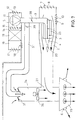
- Fig. 1 shows a vertical section of a hall 1, the Walls and ceiling are heat insulated. This one doors not shown, but especially the loading gates, are designed so that they are lock-like when loading are sealed and accordingly practically no air exchange can take place with the hall environment.
- a suction chamber 2 in the ceiling area arranged, in which a pressure channel 3 with a driving nozzle arrangement 4 opens out.
- the pressure channel 3 is on the pressure side with a Fan 5 connected.
- the suction chamber 2 points axially Extension to the driving nozzle arrangement 4 and at a distance from it an outlet nozzle arrangement 6.
- the suction chamber 2 is facing away from the outlet nozzle arrangement 6 Side provided with an inlet opening 7, the the conditioned air is connected and the one with a Flap arrangement 8 can be opened and closed.
- the suction chamber 2 is also in this end region with a further inlet opening 9 provided that opens into the hall interior and which open and open via a corresponding flap arrangement 10 is lockable.
- the blower is assigned an inlet chamber 11, which is optional via an inlet opening 12 with a flap arrangement 13 with the conditioned air and via an opening 14 with Flap arrangement 15 in turn via a ballast chamber 16 optionally via an inlet opening 17 and an inlet opening 18 either with the conditioned air or with the Hall is connectable.
- a temperature unit 19 may be arranged, depending on the application, as a cooling device or as a heating device is trained.
- a warehouse is now located in an area with high daytime temperatures but low nighttime temperatures, it is possible with the aid of such a device to cool the hall accordingly.
- cool conditioned air is drawn in via the blower 5 during the cool night period and a propellant jet 20 is generated via the propelling nozzle arrangement 4 at a high air speed of, for example, 50 m per second.
- a delivery capacity of between 50,000 and 200,000 m 3 / h, depending on the size of the hall, conditioned air is now entrained via one or two suction chambers 2 by means of the propulsion jet 20 from the suction chamber 2.
- the inlet opening 7 is opened for conditioned air, while the inlet opening 9 is closed towards the hall.
- the cool conditioned air here called conditioned air
- conditioned air is now entrained by the propellant jet 20 in the suction chamber 2.
- conditioned air With appropriate coordination of the distance from the exit plane of the propellant nozzle 4 to the exit plane of the outlet nozzle arrangement 6 and with corresponding cross-sectional dimensions of the propellant jet 20, about five times the air is entrained from the suction chamber 2, so that a core jet 21 of tempering air 50 m into the outlet nozzle assembly 6 Hall is blown out with an initial speed of, for example, 7.5 m / s, so that a hall length of approximately 50 m can be bridged, an air speed in the area of the hall end of approximately 0.5 m / s being ascertainable.
- the core jet 21 also entrains air from the hall. Since both the propulsion jet 20 and the Suction chamber 2 can be supplied with cool conditioned air via an outlet opening 22 in open during the night the wall of the hall warmed up in the hall during the daytime Air is displaced to the outside.
- the device described with reference to Fig. 1 can also used to temper the hall air in the sense of heating become.
- the temperature unit is 19th designed as a heating device, so that in a circuit the air is heated by indoor air via the fan 5 can be, so that hot air into the suction chamber as a propellant jet 2 is blown out and out of the hall accordingly the inlet opening 9 with closed inlet openings 7 and 12 the hall air can be circulated.
- a heating up up to 70 ° C may be appropriate depending on the temperature his.
- An air exchange can be effected here if a small amount of fresh air via the inlet opening 17 the heater 19 is supplied and in the same way a corresponding amount of indoor air via the outlet opening 22 is discharged to the outside.
- the pressure channel 3 does not need to be thermally insulated in this application to be executed. It is advisable if the pressure channel 3 made of heat-conducting material, for example Sheet steel, is made so that through the suction chamber 2 Air flowing along the pressure channel 3 is already warming up can. It is to improve heat transfer useful if at least the horizontal one Part of the pressure channel 3 provided with heat transfer surfaces 23 is. These can be smooth or wavy Web plates may be formed so as to keep the contact surface between the air flowing along and the pressure channel 3 to enlarge.
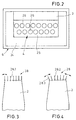
- FIG 2 is a view of the outlet nozzle assembly 6 shown.
- the one representing the free flow cross section Nozzle opening 24 has approximately the same contour as in FIG this view visible propulsion nozzle arrangement 4, but with larger cross section.
- the pressure channel 3 at least in the end region in front of the Driving nozzle arrangement 4 designed as a rectangular channel.
- the Pressure channel 3 is closed here with an end wall 25, in which several individual nozzles 26 side by side and in two Rows arranged one above the other, for example offset from one another are. From this propulsion nozzle arrangement, the Driving jet 20 as a "bundle" of individual jets.
- the suction effect of the propulsion nozzle arrangement 4 can still be done be improved if the horizontal part of the pressure channel 3 divided into individual tubes over at least part of its length is, which then each end in a single nozzle 26.
- About the ratio of the theoretical beam cross section of the propulsion jet 20 composed of many individual jets and the free passage cross section 24 of the outlet nozzle arrangement 4 can then both the total amount of air and the exit speed of the emerging from the outlet nozzle assembly Air jet 21 are influenced.
- the outlet nozzle assembly 6 in Outlet area with means 28 for beam alignment and / or Provide beamforming.
- this means 28 by pivoting slats, which from swiveled horizontally up or down can be changed in order to change the beam direction.
- FIG. 4 shows a modification of the embodiment according to FIG. 3 shown.
- the embodiment according to FIG. 3 can also be with a motor Drive are provided so that the slats 28.2 periodically or can be pivoted back and forth continuously, so that the emerging from the outlet nozzle assembly 6 Tempering air jet 21 in different hall areas can be blown.
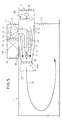
- FIG. 5 is a modified embodiment of the device acc. Fig. 1 shown.
- the basic structure is identical, so that the same components and functional elements with the same Reference numerals are provided and accordingly to the description can be referred to Fig. 1.
- the valve assembly 10 closed and the flap arrangement 8 of the inlet opening 7 opened and at least in the initial phase for generation a high air flow, the fan 29 in operation taken. Because of the fan 29 that of the driving nozzle arrangement 4 supplied air volume already an increased basic speed has, the energy losses at Speed increase of the total air volume through the Propellant jet 20 reduced, so that an increased amount of air with increased flow velocity through the outlet nozzle arrangement 6 can be introduced into the hall.
- This arrangement of an additional fan 29 has here the further advantage that the blower 5 in its performance in essentially on "normal operation", d. H. the operation during of the day to maintain air circulation through the hall, d. H. so designed with lower power can be because the higher required for night operation Power then by the additional fan 29 at least is temporarily applied.
- FIG. 6 is a compared to the embodiment according to.
- Fig. 1 modified embodiment as shown in particular is used when the device according to the invention is used to heat a hall.
- This modified too Embodiment corresponds essentially in the basic structure the embodiment acc. Fig. 1, so that same Components are marked with the same reference numerals and accordingly referred to the description of FIG. 1 can be.
- the suction chamber 2 with a Provide inlet 7.1, which is open to the hall interior is.
- a ring nozzle acting pipe section 30 is provided in which a small Axial fan 29.1 is arranged.
- the suction chamber is provided with a flap arrangement 31, the "normal operation", d. i.e. when the air circulation is maintained only via the propulsion jet 20, opened is.
- the axial fan 29.1 is also expedient here designed so that it has a low flow resistance at standstill having.
- one can regulate its performance Axial fan 29.1 are provided for the heating phase with high speed and correspondingly high delivery rate is operated and during "normal operation" at a reduced speed and therefore only with a low delivery rate is operated.
- This reduced delivery rate will set so that essentially the flow losses between the inlet opening 7.1 and the driving nozzle arrangement 4 are balanced, so that again, as above already for the design according to Fig. 5 mentions Generation of the propulsion jet for "normal operation" a smaller one Blower 5 can be used because of the flow losses between the inlet opening 7.1 and the driving nozzle arrangement 4 and the flow losses when increasing the speed the inflowing conditioned air via the fan 29.1 be balanced.
- a by-pass line are branched off, through which a partial flow of the fan air blown into the suction chamber 2 as conditioned air be seen in the flow direction before the Driving nozzle 4, so that here too the desired pressure increase the conditioned air is given.
- the blower 5 should expediently for a correspondingly high delivery rate designed and with a drive motor adjustable in speed be connected.
- outlet nozzle arrangement 6 A large number of tubular nozzles 61 and 6.2 arranged side by side to form, at least partially at an angle to Main axis of the driving jet can be aligned.
- Shape of the outlet nozzle assembly 6 with a variety of side-by-side pipe nozzles 6.1 and 6.2 indicated.
- a smaller flow cross section will provided by the pipe nozzles 6.2, which in their Beam direction down at an angle to the hall ceiling are aligned.
- Flap assemblies 32 and 33 can now either the inflow to the pipe nozzles 6.1 and / or to the Pipe nozzles 6.2 are opened or closed.
- the design is intended so that the pipe nozzles 6.1 for the "normal operation” described above, i. H. with a promotion of the tempering air essentially are opened via the driving jet 20.
- the flaps 32 are closed and the flaps 33 opened so that heated tempering air directed at high speed and obliquely downwards can enter the hall.
- the heated one entering the hall interior Tempering air is prevented from being warmed up Tempering air immediately after exiting the Outlet nozzle arrangement 6 "bears" on the hall ceiling.
- the arrangement acc. Fig. 5 can, depending on the structural conditions also carried out with a fan arrangement 29.1, 30, 31 as shown in FIG. 6.
- the embodiment acc. 6 can accordingly also with a large fan, 5 as shown.
- FIG. 7 is a modification of the embodiment according to. Fig. 5 or Fig. 6, as shown in particular for Heating a hall with one or more air outlets under the hall ceiling is useful if these air outlets not just in one direction, but from each The tempering air in on all sides of the ceiling hand over the hall.
- the basic structure corresponds again that described above for the individual embodiments Construction. The difference is in the embodiment acc. Fig. 7, however, in that of the nozzle assembly 4 leading pressure channel 3 a pressure channel 3.1 is branched off, arranged in one on the outlet side of the suction chamber 2 Cross channel 34 opens out.
- the preferably vertically down transverse channel 34 aligned with the hall is with a Outlet head 35 provided with an outlet nozzle arrangement 6 is provided by the temperature control air to be supplied to the hall preferably substantially in the horizontal direction Blown in at a slight angle downward becomes.
- a auxiliary fan 36 which the air flowing in from the suction chamber 2 down into the Exhaust head 35 deflects.
- Via a flap arrangement 37 in the entry area of the branched pressure channel 3.1 in the transverse channel 34 can in addition to that via the branched pressure channel 3.1 supplied hot air still recirculated heated room air become.
- an adjusting flap 38 in the pressure channel 3 and an adjusting flap 39 in the branched pressure channel 3.1 can now be in any desired Way over the distribution of at high speed hot air to be supplied to the blower.
- an additional fan in the suction chamber 2 according to the arrangement of the fan 29 acc. Fig. 5 or 6 can be arranged, the supply of room air and the one to be returned to the room after the tempering Air volume and also the exit speed at Aulsass head can be regulated.
- a heating register is arranged by a heat supply device for example with a liquid hot Heat transfer medium is applied.
- This heat supply device can also with the temperature unit assigned to the blower 5 19 connected in this embodiment is then also designed as a heating register. So that exists the possibility of using a jet nozzle 4 guided "base load" required in the event of strong temperature fluctuations peak loads on such a heating register in the transverse duct 34 and the associated auxiliary fan 36 level out.
- Fig. 8 shows a modification of the embodiment according to. Fig. 1.
- the propellant nozzle arrangement that draws air from the suction chamber 2 4 is another air induction propelling nozzle arrangement 4.1 downstream, in such a way that the Air outlet of the suction chamber 2 is designed so that a Propulsion jet 20.1 arises which has a lower flow rate with a larger amount of air.
- This one more Propellant jet 20.1 is passed through an air intake 2.1, in the from the environment through side openings 2.2 further amounts of air are sucked in, so that from the outlet nozzle arrangement 6.1 a correspondingly large amount of air with reduced Speed emerges.
Landscapes
- Engineering & Computer Science (AREA)
- Chemical & Material Sciences (AREA)
- Combustion & Propulsion (AREA)
- Mechanical Engineering (AREA)
- General Engineering & Computer Science (AREA)
- Duct Arrangements (AREA)
- Central Air Conditioning (AREA)
- Heat Treatment Of Articles (AREA)
- Forging (AREA)
- Processing And Handling Of Plastics And Other Materials For Molding In General (AREA)
- Jet Pumps And Other Pumps (AREA)
Abstract
Description
- Fig. 1
- einen Vertikalschnitt durch eine Halle mit Saugkammer, Gebläse Treibdüsenanordnung und Auslaßdüsenanordnung,
- Fig. 2
- eine Aufsicht auf die Auslaßseite der Saugkammer,
- Fig. 3
- eine andere Ausführungsform eines Mittels zur Strahlausrichtung,
- Fig. 4
- eine Abwandlung der Ausführungsform gemäß Fig. 3,
- Fig. 5
- eine modifizierte Ausführungsform der Saugkammer,
- Fig. 6
- eine weitere modifizierte Ausführungsform mit einer abgewandelten Auslaßdüsenanordnung,
- Fig. 7
- eine Abwandlung der Ausführungsform gem. Fig. 6,
- Fig. 8
- eine Abwandlung der Ausführungsform gem. Fig. 1.
Claims (23)
- Verfahren zur Temperierung einer Halle, insbesondere einer Lagerhalle, bei dem über eine mit einem Gebläse verbundene Treibdüsenanordnung ein Treibstrahl mit hoher Strömungsgeschwindigkeit erzeugt wird, der durch eine mit einer Auslaßdüsenanordnung versehene Saugkammer geführt wird, wobei über die Saugkammer konditionierte Luft angesaugt wird, die zusammen mit dem Treibstrahl als Temperierungsluft in die Halle eingeblasen wird.
- Verfahren nach Anspruch 1, dadurch gekennzeichnet, daß die Temperierungsluft im Deckenbereich, vorzugsweise entlang der Hallendecke eingeblasen wird.
- Verfahren nach Anspruch 1 oder 2, dadurch gekennzeichnet, daß zumindest eine Luftteilmenge als konditionierte Luft aus der Halle der Saugkammer zugeführt wird.
- Verfahren nach einem der Ansprüche 1 bis 3 dadurch gekennzeichnet, daß zumindest eine Luftteilmenge als konditionierte Luft durch Konditionierte Luft der Saugkammer zugeführt wird.
- Verfahren nach einem der Ansprüche 1 bis 4, dadurch gekennzeichnet, daß die Luft für den Treibstrahl aus der Halle abgesaugt wird.
- Verfahren nach einem der Ansprüche 1 bis 5, dadurch gekennzeichnet, daß bei hohen Tagesaußentemperaturen während der Nachtzeit zur Erzeugung des Treibstrahls und/oder als konditionierte Luft kühle Konditionierte Luft angesaugt wird.
- Verfahren nach einem der Ansprüche 1 bis 6, dadurch gekennzeichnet, daß zumindest ein Teil der Hallenluft nach außen abgeführt wird.
- Verfahren nach einem der Ansprüche 1 bis 7, dadurch gekennzeichnet, daß die konditionierte Luft im Kreislauf über die Halle geführt wird.
- Verfahren nach einem der Ansprüche 1 bis 8, dadurch gekennzeichnet, daß je nach Außentemperatur die Luft für den Treibstrahl gekühlt oder erhitzt wird.
- Verfahren nach einem der Ansprüche 1 bis 9, dadurch gekennzeichnet, daß der Saugkammer zumindest zeitweise und/oder wenigstens ein Teil der konditionierten Luft unter Druck zugeführt wird.
- Verfahren nach einem der Ansprüche 1 bis 10, dadurch gekennzeichnet, daß konditionierte Luft unter Druck in Richtung des Treibstrahls durch die Saugkammer geführt wird.
- Verfahren nach einem der Ansprüche 1 bis 11, dadurch gekennzeichnet, daß in Strömungsrichtung gesehen vor dem Eintritt des Treibstrahls in die Saugkammer konditionierte Luft unter Druck in die Saugkammer eingeführt wird.
- Verfahren nach einem der Ansprüche 1 bis 12, dadurch gekennzeichnet, daß in Strömungsrichtung gesehen, hinter dem Eintritt des Treibstrahls in die Saugkammer, Luft unter Druck eingeführt wird.
- Verfahren nach Anspruch 13, dadurch gekennzeichnet, daß die Luft quer zur Strahlrichtung des Treibstrahls eingeführt wird und diesen unter gleichzeitiger Vermischung umlenkt.
- Verfahren nach einem der Ansprüche 1 bis 14, dadurch gekennzeichnet, daß die Strömungsgeschwindigkeit des aus einer ersten Treibdüsenanordnung austretenden, luftansaugenden Treibstrahls mittels wenigstens einer weiteren luftansaugenden Treibdüsenanordnung durch zusätzlich angesaugte Luftmengen herabgesetzt wird, wobei ein neuer Treibstrahl mit geringerer Strömungsgeschwindigkeit gebildet wird.
- Einrichtung zur Temperierung einer Halle, insbesondere einer Lagerhalle, nach dem Verfahren gemäß den Ansprüchen 1 bis 15, mit einem Gebläse (5), das druckseitig über einen Druckkanal (3) mit einer Treibdüsenanordnung (4) verbunden ist, die in einer Saugkammer (2) ausmündet, wobei die Saugkammer (2) in axialer Zuordnung und mit Abstand zur Treibdüsenanordnung (4) eine Auslaßdüsenanordnung (6) aufweist und mit wenigstens einer öffen- und schließbaren Einlaßöffnung (7) für Konditionierte Luft und wenigstens einer öffen- und schließbaren Einlaßöffnung (9) für Hallenluft versehen ist.
- Einrichtung nach Anspruch 16, dadurch gekennzeichnet, daß das Gebläse (5) saugseitig mit einer Einlaßkammer (11) verbunden ist, die wahlweise zur Konditionierte Luft und/oder zur Halle öffenbar ist.
- Einrichtung nach einem der Ansprüche 16 oder 17, dadurch gekennzeichnet, daß die Treibdüsenanordnung (4) eine Vielzahl nebeneinander angeordneter Einzeldüsen (26) aufweist, die den mit der Druckseite des Gebläses (5) verbundenen Druckkanal (3) abschließen.
- Einrichtung nach einem der Ansprüche 16 bis 18, dadurch gekennzeichnet, daß die Öffnungskontur der Auslaßdüsenanordnung (6) in etwa einer vergrößerten Projektion der Treibdüsenanordnung (4) entspricht.
- Einrichtung nach einem der Ansprüche 16 bis 19, dadurch gekennzeichnet, daß die Auslaßdüsenanordnung (6) Mittel (28) zur Strahlausrichtung und/oder Strahlformung aufweist.
- Einrichtung nach einem der Ansprüche 16 bis 20, dadurch gekennzeichnet, daß der in der Saugkammer (2) verlaufende Teil des Druckkanals (3) auf seiner Außenseite mit Wärmeübertragungsflächen (23) versehen ist.
- Einrichtung nach einem der Ansprüche 16 bis 21, dadurch gekennzeichnet, daß die Saugkammer (2) in Strömungsrichtung gesehen vor der Ausmündung der Treibdüsenanordnung (4) einen Ventilator (29) zur Beschleunigung der konditionierten Luft aufweist.
- Einrichtung nach einem der Ansprüche 16 bis 22, dadurch gekennzeichnet, daß der mit dem Gebläse (5) direkt in Verbindung stehenden luftansaugenden Treibdüsenanordnung (4) mit Abstand wenigstens eine weitere luftansaugende Treibdüsenanordnung (4.1) zugeordnet ist, durch die ein neuer Treibstrahl (20.1) mit geringerer Strömungsgeschwindigkeit und größerer Luftmenge gebildet wird.
Applications Claiming Priority (6)
| Application Number | Priority Date | Filing Date | Title |
|---|---|---|---|
| DE19910759 | 1999-03-11 | ||
| DE19910759 | 1999-03-11 | ||
| DE19918594 | 1999-04-23 | ||
| DE19918594 | 1999-04-23 | ||
| DE19921463 | 1999-05-08 | ||
| DE19921463A DE19921463A1 (de) | 1999-03-11 | 1999-05-08 | Verfahren zur Temperierung einer Halle und Einrichtung zur Durchführung des Verfahrens |
Publications (3)
| Publication Number | Publication Date |
|---|---|
| EP1035385A2 true EP1035385A2 (de) | 2000-09-13 |
| EP1035385A3 EP1035385A3 (de) | 2000-10-04 |
| EP1035385B1 EP1035385B1 (de) | 2005-11-16 |
Family
ID=27219017
Family Applications (1)
| Application Number | Title | Priority Date | Filing Date |
|---|---|---|---|
| EP00104492A Expired - Lifetime EP1035385B1 (de) | 1999-03-11 | 2000-03-09 | Verfahren zur Temperierung einer Halle und Einrichtung zur Durchführung des Verfahrens |
Country Status (3)
| Country | Link |
|---|---|
| EP (1) | EP1035385B1 (de) |
| AT (1) | ATE310214T1 (de) |
| DE (1) | DE50011597D1 (de) |
Cited By (5)
| Publication number | Priority date | Publication date | Assignee | Title |
|---|---|---|---|---|
| FR2833339A1 (fr) * | 2001-12-10 | 2003-06-13 | Bense Dominique | Dispositif de traitement d'air |
| FR2916261A1 (fr) * | 2007-05-18 | 2008-11-21 | Alain Katz | Systeme de diffusion d'air dans une enceinte |
| US9343885B2 (en) | 2009-08-06 | 2016-05-17 | 3M Innovative Properties Company | System and method for providing final drop in a living unit in a building |
| CN106567356A (zh) * | 2014-03-10 | 2017-04-19 | 苏州宝时得电动工具有限公司 | 吹吸装置 |
| WO2021223648A1 (zh) * | 2020-07-30 | 2021-11-11 | 青岛海尔空调器有限总公司 | 用于柜式空调室内机的射流装置及柜式空调室内机 |
Families Citing this family (1)
| Publication number | Priority date | Publication date | Assignee | Title |
|---|---|---|---|---|
| IT202300014301A1 (it) * | 2023-07-07 | 2025-01-07 | Stiga S P A In Breve Anche St S P A | Soffiatore portatile, relativo accessorio di soffiatura e relativo metodo di soffiatura |
Family Cites Families (4)
| Publication number | Priority date | Publication date | Assignee | Title |
|---|---|---|---|---|
| DE2719499C3 (de) * | 1977-05-02 | 1981-09-24 | Schmidt-Reuter Ingenieurgesellschaft mbH & Co KG, 5000 Köln | Induktionsgerät für eine Hochdruckklimaanlage |
| DE3216997C2 (de) * | 1982-05-06 | 1985-01-10 | Schako Metallwarenfabrik Ferdinand Schad Kg, 7201 Kolbingen | Fensterblasgerät für Lüftungs- und Klimaanlagen |
| NO844320L (no) * | 1984-10-30 | 1986-05-02 | Norsk Viftefabrikk As | Fremgangsmaate ved ventilasjon av rom. |
| DE8902355U1 (de) * | 1989-02-28 | 1989-05-03 | Ltg Lufttechnische Gmbh, 7000 Stuttgart | Düsenkasten |
-
2000
- 2000-03-09 EP EP00104492A patent/EP1035385B1/de not_active Expired - Lifetime
- 2000-03-09 DE DE50011597T patent/DE50011597D1/de not_active Expired - Fee Related
- 2000-03-09 AT AT00104492T patent/ATE310214T1/de not_active IP Right Cessation
Cited By (7)
| Publication number | Priority date | Publication date | Assignee | Title |
|---|---|---|---|---|
| FR2833339A1 (fr) * | 2001-12-10 | 2003-06-13 | Bense Dominique | Dispositif de traitement d'air |
| EP1319901A1 (de) * | 2001-12-10 | 2003-06-18 | Dominique Bense | Luftbehandlungsanlage |
| FR2916261A1 (fr) * | 2007-05-18 | 2008-11-21 | Alain Katz | Systeme de diffusion d'air dans une enceinte |
| WO2008142348A3 (fr) * | 2007-05-18 | 2009-02-19 | Boone Charles | Systeme de diffusion d'air dans une enceinte |
| US9343885B2 (en) | 2009-08-06 | 2016-05-17 | 3M Innovative Properties Company | System and method for providing final drop in a living unit in a building |
| CN106567356A (zh) * | 2014-03-10 | 2017-04-19 | 苏州宝时得电动工具有限公司 | 吹吸装置 |
| WO2021223648A1 (zh) * | 2020-07-30 | 2021-11-11 | 青岛海尔空调器有限总公司 | 用于柜式空调室内机的射流装置及柜式空调室内机 |
Also Published As
| Publication number | Publication date |
|---|---|
| DE50011597D1 (de) | 2005-12-22 |
| ATE310214T1 (de) | 2005-12-15 |
| EP1035385B1 (de) | 2005-11-16 |
| EP1035385A3 (de) | 2000-10-04 |
Similar Documents
| Publication | Publication Date | Title |
|---|---|---|
| EP3504363B1 (de) | Oxidationsofen | |
| DE3505256C2 (de) | Vorrichtung zum berührungsfreien Führen von Warenbahnen, insbesondere Metallbändern, mittels eines Gasmediums | |
| DE3874344T2 (de) | Verfahren zur lueftung und lueftungsanlage. | |
| DE69815867T2 (de) | Schwebetrocknereinheit | |
| EP2611955A1 (de) | Oxidationsofen | |
| DE3612720C2 (de) | ||
| CH411009A (de) | Kühltruhe | |
| DE1455835B1 (de) | Vorrichtung zum Heizen und Belüften von Kraftfahrzeugen | |
| EP1035385B1 (de) | Verfahren zur Temperierung einer Halle und Einrichtung zur Durchführung des Verfahrens | |
| EP2141429B1 (de) | Hybridkühlturm | |
| DE4026107A1 (de) | Konvektions-trocken und/oder -fixiermaschine | |
| DE19525945C2 (de) | Verfahren und Vorrichtung zur Erzeugung behaglicher Raumluftzustände | |
| DE2033195C3 (de) | Luftaustrittseinrichtung für Klimaanlagen | |
| EP0657702B1 (de) | Anordnung zur Erzeugung zweier gegenläufiger Luftschleier | |
| DE19921463A1 (de) | Verfahren zur Temperierung einer Halle und Einrichtung zur Durchführung des Verfahrens | |
| DE3322075C2 (de) | Gerät zum Temperieren der Luft innerhalb eines Raumes | |
| DE20011500U1 (de) | Raumlufttechnische Einrichtung, insbesondere zur Klimatisierung großer Hallen | |
| EP3294627B1 (de) | Belüftungsvorrichtung für einen geschlossenen vertikalwindtunnel | |
| DE2446983A1 (de) | Vorrichtung zur beidseitigen beblasung eines bahnfoermigen materials | |
| DE3872532T2 (de) | Verfahren und luftverteilungsmittel zum zufuehren von luft in einen raumbereich. | |
| EP3477212B1 (de) | Luftverteilvorrichtung sowie verfahren zur belüftung eines raumes | |
| DE4303307C2 (de) | Vorrichtung zur Kühlung von Räumen | |
| DE1800098A1 (de) | Verfahren und Vorrichtung zur Erzeugung eines Torluftvorhanges | |
| DE3437237C2 (de) | ||
| DE3918564A1 (de) | Luftheizer |
Legal Events
| Date | Code | Title | Description |
|---|---|---|---|
| PUAI | Public reference made under article 153(3) epc to a published international application that has entered the european phase |
Free format text: ORIGINAL CODE: 0009012 |
|
| PUAL | Search report despatched |
Free format text: ORIGINAL CODE: 0009013 |
|
| AK | Designated contracting states |
Kind code of ref document: A2 Designated state(s): AT BE CH CY DE DK ES FI FR GB GR IE IT LI LU MC NL PT SE |
|
| AX | Request for extension of the european patent |
Free format text: AL;LT;LV;MK;RO;SI |
|
| AK | Designated contracting states |
Kind code of ref document: A3 Designated state(s): AT BE CH CY DE DK ES FI FR GB GR IE IT LI LU MC NL PT SE |
|
| AX | Request for extension of the european patent |
Free format text: AL;LT;LV;MK;RO;SI |
|
| 17P | Request for examination filed |
Effective date: 20010317 |
|
| AKX | Designation fees paid |
Free format text: AT BE CH CY DE DK ES FI FR GB GR IE IT LI LU MC NL PT SE |
|
| 17Q | First examination report despatched |
Effective date: 20030304 |
|
| GRAP | Despatch of communication of intention to grant a patent |
Free format text: ORIGINAL CODE: EPIDOSNIGR1 |
|
| GRAS | Grant fee paid |
Free format text: ORIGINAL CODE: EPIDOSNIGR3 |
|
| GRAA | (expected) grant |
Free format text: ORIGINAL CODE: 0009210 |
|
| AK | Designated contracting states |
Kind code of ref document: B1 Designated state(s): AT BE CH CY DE DK ES FI FR GB GR IE IT LI LU MC NL PT SE |
|
| PG25 | Lapsed in a contracting state [announced via postgrant information from national office to epo] |
Ref country code: IT Free format text: LAPSE BECAUSE OF FAILURE TO SUBMIT A TRANSLATION OF THE DESCRIPTION OR TO PAY THE FEE WITHIN THE PRESCRIBED TIME-LIMIT;WARNING: LAPSES OF ITALIAN PATENTS WITH EFFECTIVE DATE BEFORE 2007 MAY HAVE OCCURRED AT ANY TIME BEFORE 2007. THE CORRECT EFFECTIVE DATE MAY BE DIFFERENT FROM THE ONE RECORDED. Effective date: 20051116 Ref country code: GB Free format text: LAPSE BECAUSE OF FAILURE TO SUBMIT A TRANSLATION OF THE DESCRIPTION OR TO PAY THE FEE WITHIN THE PRESCRIBED TIME-LIMIT Effective date: 20051116 Ref country code: NL Free format text: LAPSE BECAUSE OF FAILURE TO SUBMIT A TRANSLATION OF THE DESCRIPTION OR TO PAY THE FEE WITHIN THE PRESCRIBED TIME-LIMIT Effective date: 20051116 Ref country code: IE Free format text: LAPSE BECAUSE OF FAILURE TO SUBMIT A TRANSLATION OF THE DESCRIPTION OR TO PAY THE FEE WITHIN THE PRESCRIBED TIME-LIMIT Effective date: 20051116 Ref country code: FI Free format text: LAPSE BECAUSE OF FAILURE TO SUBMIT A TRANSLATION OF THE DESCRIPTION OR TO PAY THE FEE WITHIN THE PRESCRIBED TIME-LIMIT Effective date: 20051116 |
|
| REG | Reference to a national code |
Ref country code: GB Ref legal event code: FG4D Free format text: NOT ENGLISH |
|
| REG | Reference to a national code |
Ref country code: CH Ref legal event code: EP |
|
| REG | Reference to a national code |
Ref country code: IE Ref legal event code: FG4D Free format text: LANGUAGE OF EP DOCUMENT: GERMAN |
|
| REF | Corresponds to: |
Ref document number: 50011597 Country of ref document: DE Date of ref document: 20051222 Kind code of ref document: P |
|
| PG25 | Lapsed in a contracting state [announced via postgrant information from national office to epo] |
Ref country code: SE Free format text: LAPSE BECAUSE OF FAILURE TO SUBMIT A TRANSLATION OF THE DESCRIPTION OR TO PAY THE FEE WITHIN THE PRESCRIBED TIME-LIMIT Effective date: 20060216 Ref country code: DK Free format text: LAPSE BECAUSE OF FAILURE TO SUBMIT A TRANSLATION OF THE DESCRIPTION OR TO PAY THE FEE WITHIN THE PRESCRIBED TIME-LIMIT Effective date: 20060216 Ref country code: GR Free format text: LAPSE BECAUSE OF FAILURE TO SUBMIT A TRANSLATION OF THE DESCRIPTION OR TO PAY THE FEE WITHIN THE PRESCRIBED TIME-LIMIT Effective date: 20060216 |
|
| PG25 | Lapsed in a contracting state [announced via postgrant information from national office to epo] |
Ref country code: ES Free format text: LAPSE BECAUSE OF FAILURE TO SUBMIT A TRANSLATION OF THE DESCRIPTION OR TO PAY THE FEE WITHIN THE PRESCRIBED TIME-LIMIT Effective date: 20060227 |
|
| PG25 | Lapsed in a contracting state [announced via postgrant information from national office to epo] |
Ref country code: AT Free format text: LAPSE BECAUSE OF NON-PAYMENT OF DUE FEES Effective date: 20060309 |
|
| PG25 | Lapsed in a contracting state [announced via postgrant information from national office to epo] |
Ref country code: LU Free format text: LAPSE BECAUSE OF NON-PAYMENT OF DUE FEES Effective date: 20060331 Ref country code: CH Free format text: LAPSE BECAUSE OF NON-PAYMENT OF DUE FEES Effective date: 20060331 Ref country code: BE Free format text: LAPSE BECAUSE OF NON-PAYMENT OF DUE FEES Effective date: 20060331 Ref country code: LI Free format text: LAPSE BECAUSE OF NON-PAYMENT OF DUE FEES Effective date: 20060331 Ref country code: MC Free format text: LAPSE BECAUSE OF NON-PAYMENT OF DUE FEES Effective date: 20060331 |
|
| PG25 | Lapsed in a contracting state [announced via postgrant information from national office to epo] |
Ref country code: PT Free format text: LAPSE BECAUSE OF FAILURE TO SUBMIT A TRANSLATION OF THE DESCRIPTION OR TO PAY THE FEE WITHIN THE PRESCRIBED TIME-LIMIT Effective date: 20060417 |
|
| NLV1 | Nl: lapsed or annulled due to failure to fulfill the requirements of art. 29p and 29m of the patents act | ||
| GBV | Gb: ep patent (uk) treated as always having been void in accordance with gb section 77(7)/1977 [no translation filed] |
Effective date: 20051116 |
|
| REG | Reference to a national code |
Ref country code: IE Ref legal event code: FD4D |
|
| PLBE | No opposition filed within time limit |
Free format text: ORIGINAL CODE: 0009261 |
|
| STAA | Information on the status of an ep patent application or granted ep patent |
Free format text: STATUS: NO OPPOSITION FILED WITHIN TIME LIMIT |
|
| PG25 | Lapsed in a contracting state [announced via postgrant information from national office to epo] |
Ref country code: DE Free format text: LAPSE BECAUSE OF NON-PAYMENT OF DUE FEES Effective date: 20061003 |
|
| 26N | No opposition filed |
Effective date: 20060817 |
|
| REG | Reference to a national code |
Ref country code: CH Ref legal event code: PL |
|
| EN | Fr: translation not filed | ||
| BERE | Be: lapsed |
Owner name: BERNHARDT, ADAM Effective date: 20060331 |
|
| PG25 | Lapsed in a contracting state [announced via postgrant information from national office to epo] |
Ref country code: FR Free format text: LAPSE BECAUSE OF FAILURE TO SUBMIT A TRANSLATION OF THE DESCRIPTION OR TO PAY THE FEE WITHIN THE PRESCRIBED TIME-LIMIT Effective date: 20070105 |
|
| PG25 | Lapsed in a contracting state [announced via postgrant information from national office to epo] |
Ref country code: FR Free format text: LAPSE BECAUSE OF FAILURE TO SUBMIT A TRANSLATION OF THE DESCRIPTION OR TO PAY THE FEE WITHIN THE PRESCRIBED TIME-LIMIT Effective date: 20060331 |
|
| PG25 | Lapsed in a contracting state [announced via postgrant information from national office to epo] |
Ref country code: FR Free format text: LAPSE BECAUSE OF FAILURE TO SUBMIT A TRANSLATION OF THE DESCRIPTION OR TO PAY THE FEE WITHIN THE PRESCRIBED TIME-LIMIT Effective date: 20051116 Ref country code: CY Free format text: LAPSE BECAUSE OF FAILURE TO SUBMIT A TRANSLATION OF THE DESCRIPTION OR TO PAY THE FEE WITHIN THE PRESCRIBED TIME-LIMIT Effective date: 20051116 |