EP1035331B1 - Distributeur piloté - Google Patents
Distributeur piloté Download PDFInfo
- Publication number
- EP1035331B1 EP1035331B1 EP19990126259 EP99126259A EP1035331B1 EP 1035331 B1 EP1035331 B1 EP 1035331B1 EP 19990126259 EP19990126259 EP 19990126259 EP 99126259 A EP99126259 A EP 99126259A EP 1035331 B1 EP1035331 B1 EP 1035331B1
- Authority
- EP
- European Patent Office
- Prior art keywords
- valve
- control
- pilot
- pressure
- pressure medium
- Prior art date
- Legal status (The legal status is an assumption and is not a legal conclusion. Google has not performed a legal analysis and makes no representation as to the accuracy of the status listed.)
- Expired - Lifetime
Links
Images


Classifications
-
- F—MECHANICAL ENGINEERING; LIGHTING; HEATING; WEAPONS; BLASTING
- F15—FLUID-PRESSURE ACTUATORS; HYDRAULICS OR PNEUMATICS IN GENERAL
- F15B—SYSTEMS ACTING BY MEANS OF FLUIDS IN GENERAL; FLUID-PRESSURE ACTUATORS, e.g. SERVOMOTORS; DETAILS OF FLUID-PRESSURE SYSTEMS, NOT OTHERWISE PROVIDED FOR
- F15B13/00—Details of servomotor systems ; Valves for servomotor systems
- F15B13/02—Fluid distribution or supply devices characterised by their adaptation to the control of servomotors
- F15B13/06—Fluid distribution or supply devices characterised by their adaptation to the control of servomotors for use with two or more servomotors
- F15B13/08—Assemblies of units, each for the control of a single servomotor only
- F15B13/0803—Modular units
- F15B13/0832—Modular valves
-
- F—MECHANICAL ENGINEERING; LIGHTING; HEATING; WEAPONS; BLASTING
- F15—FLUID-PRESSURE ACTUATORS; HYDRAULICS OR PNEUMATICS IN GENERAL
- F15B—SYSTEMS ACTING BY MEANS OF FLUIDS IN GENERAL; FLUID-PRESSURE ACTUATORS, e.g. SERVOMOTORS; DETAILS OF FLUID-PRESSURE SYSTEMS, NOT OTHERWISE PROVIDED FOR
- F15B13/00—Details of servomotor systems ; Valves for servomotor systems
- F15B13/02—Fluid distribution or supply devices characterised by their adaptation to the control of servomotors
- F15B13/04—Fluid distribution or supply devices characterised by their adaptation to the control of servomotors for use with a single servomotor
- F15B13/0401—Valve members; Fluid interconnections therefor
- F15B13/0405—Valve members; Fluid interconnections therefor for seat valves, i.e. poppet valves
-
- F—MECHANICAL ENGINEERING; LIGHTING; HEATING; WEAPONS; BLASTING
- F15—FLUID-PRESSURE ACTUATORS; HYDRAULICS OR PNEUMATICS IN GENERAL
- F15B—SYSTEMS ACTING BY MEANS OF FLUIDS IN GENERAL; FLUID-PRESSURE ACTUATORS, e.g. SERVOMOTORS; DETAILS OF FLUID-PRESSURE SYSTEMS, NOT OTHERWISE PROVIDED FOR
- F15B13/00—Details of servomotor systems ; Valves for servomotor systems
- F15B13/02—Fluid distribution or supply devices characterised by their adaptation to the control of servomotors
- F15B13/04—Fluid distribution or supply devices characterised by their adaptation to the control of servomotors for use with a single servomotor
- F15B13/042—Fluid distribution or supply devices characterised by their adaptation to the control of servomotors for use with a single servomotor operated by fluid pressure
-
- F—MECHANICAL ENGINEERING; LIGHTING; HEATING; WEAPONS; BLASTING
- F15—FLUID-PRESSURE ACTUATORS; HYDRAULICS OR PNEUMATICS IN GENERAL
- F15B—SYSTEMS ACTING BY MEANS OF FLUIDS IN GENERAL; FLUID-PRESSURE ACTUATORS, e.g. SERVOMOTORS; DETAILS OF FLUID-PRESSURE SYSTEMS, NOT OTHERWISE PROVIDED FOR
- F15B13/00—Details of servomotor systems ; Valves for servomotor systems
- F15B13/02—Fluid distribution or supply devices characterised by their adaptation to the control of servomotors
- F15B13/06—Fluid distribution or supply devices characterised by their adaptation to the control of servomotors for use with two or more servomotors
- F15B13/08—Assemblies of units, each for the control of a single servomotor only
- F15B13/0803—Modular units
- F15B13/0807—Manifolds
- F15B13/0817—Multiblock manifolds
-
- F—MECHANICAL ENGINEERING; LIGHTING; HEATING; WEAPONS; BLASTING
- F15—FLUID-PRESSURE ACTUATORS; HYDRAULICS OR PNEUMATICS IN GENERAL
- F15B—SYSTEMS ACTING BY MEANS OF FLUIDS IN GENERAL; FLUID-PRESSURE ACTUATORS, e.g. SERVOMOTORS; DETAILS OF FLUID-PRESSURE SYSTEMS, NOT OTHERWISE PROVIDED FOR
- F15B13/00—Details of servomotor systems ; Valves for servomotor systems
- F15B13/02—Fluid distribution or supply devices characterised by their adaptation to the control of servomotors
- F15B13/06—Fluid distribution or supply devices characterised by their adaptation to the control of servomotors for use with two or more servomotors
- F15B13/08—Assemblies of units, each for the control of a single servomotor only
- F15B13/0803—Modular units
- F15B13/0821—Attachment or sealing of modular units to each other
-
- F—MECHANICAL ENGINEERING; LIGHTING; HEATING; WEAPONS; BLASTING
- F15—FLUID-PRESSURE ACTUATORS; HYDRAULICS OR PNEUMATICS IN GENERAL
- F15B—SYSTEMS ACTING BY MEANS OF FLUIDS IN GENERAL; FLUID-PRESSURE ACTUATORS, e.g. SERVOMOTORS; DETAILS OF FLUID-PRESSURE SYSTEMS, NOT OTHERWISE PROVIDED FOR
- F15B13/00—Details of servomotor systems ; Valves for servomotor systems
- F15B13/02—Fluid distribution or supply devices characterised by their adaptation to the control of servomotors
- F15B13/06—Fluid distribution or supply devices characterised by their adaptation to the control of servomotors for use with two or more servomotors
- F15B13/08—Assemblies of units, each for the control of a single servomotor only
- F15B13/0803—Modular units
- F15B13/0846—Electrical details
- F15B13/085—Electrical controllers
-
- F—MECHANICAL ENGINEERING; LIGHTING; HEATING; WEAPONS; BLASTING
- F15—FLUID-PRESSURE ACTUATORS; HYDRAULICS OR PNEUMATICS IN GENERAL
- F15B—SYSTEMS ACTING BY MEANS OF FLUIDS IN GENERAL; FLUID-PRESSURE ACTUATORS, e.g. SERVOMOTORS; DETAILS OF FLUID-PRESSURE SYSTEMS, NOT OTHERWISE PROVIDED FOR
- F15B13/00—Details of servomotor systems ; Valves for servomotor systems
- F15B13/02—Fluid distribution or supply devices characterised by their adaptation to the control of servomotors
- F15B13/06—Fluid distribution or supply devices characterised by their adaptation to the control of servomotors for use with two or more servomotors
- F15B13/08—Assemblies of units, each for the control of a single servomotor only
- F15B13/0803—Modular units
- F15B13/0846—Electrical details
- F15B13/0857—Electrical connecting means, e.g. plugs, sockets
-
- F—MECHANICAL ENGINEERING; LIGHTING; HEATING; WEAPONS; BLASTING
- F15—FLUID-PRESSURE ACTUATORS; HYDRAULICS OR PNEUMATICS IN GENERAL
- F15B—SYSTEMS ACTING BY MEANS OF FLUIDS IN GENERAL; FLUID-PRESSURE ACTUATORS, e.g. SERVOMOTORS; DETAILS OF FLUID-PRESSURE SYSTEMS, NOT OTHERWISE PROVIDED FOR
- F15B13/00—Details of servomotor systems ; Valves for servomotor systems
- F15B13/02—Fluid distribution or supply devices characterised by their adaptation to the control of servomotors
- F15B13/06—Fluid distribution or supply devices characterised by their adaptation to the control of servomotors for use with two or more servomotors
- F15B13/08—Assemblies of units, each for the control of a single servomotor only
- F15B13/0803—Modular units
- F15B13/0875—Channels for electrical components, e.g. for cables or sensors
-
- F—MECHANICAL ENGINEERING; LIGHTING; HEATING; WEAPONS; BLASTING
- F15—FLUID-PRESSURE ACTUATORS; HYDRAULICS OR PNEUMATICS IN GENERAL
- F15B—SYSTEMS ACTING BY MEANS OF FLUIDS IN GENERAL; FLUID-PRESSURE ACTUATORS, e.g. SERVOMOTORS; DETAILS OF FLUID-PRESSURE SYSTEMS, NOT OTHERWISE PROVIDED FOR
- F15B13/00—Details of servomotor systems ; Valves for servomotor systems
- F15B2013/002—Modular valves, i.e. consisting of an assembly of interchangeable components
- F15B2013/006—Modular components with multiple uses, e.g. kits for either normally-open or normally-closed valves, interchangeable or reprogrammable manifolds
Definitions
- the invention is based on a pilot-controllable valve unit according to the preamble of independent claim 1.
- a two-way valves equipped valve unit is already known for example from US 5,103,866.
- the closure members are guided independently of each other in a common housing and arranged coaxially or parallel to each other.
- the closure members are identical to each other and provided at their ends with control piston of different dimensions.
- the closing members In operative connection with the housing-side seat bodies, the closing members each form two seat valves.
- the poppet valves have the same size valve openings and the piston surface of one of the actuating piston corresponds in its surface of a valve opening.
- the reversal takes place by changing the contacting of the various connections.
- the entire directional control valve has seven different pressure chambers. Its housing is therefore expensive to produce and takes a manufacturing technology large volume of construction.
- a vor horrbares multi-way valve is apparent.
- This has a plurality of simultaneously operable arranged on a common valve stem closing members, and a plurality of fixed and movable valve seats.
- the surface areas on which the pressure medium acts are at least partially determined by an asymmetric valve disk structure.
- the valve disks (closing members) each have two oppositely directed annular sealing surfaces of different diameters, which define different surface areas.
- the valve stem (closing element) cooperating with the valve seats is displaceably guided, piston areas of different size being provided for switching over opposing control pistons.
- valve seats have different sized valve openings. Due to the different sized pressurized surfaces, a compressive force is generated in the closing direction.
- the directional control valve constructed according to a so-called internal sealing principle is rather expensive to manufacture, in particular because of the asymmetrical valve disk configuration.
- the inventive controllable valve unit according to claim 1 has the advantage that it allows the formation of a complete valve concept to the extent mentioned above with relatively little construction effort.
- Different valve variants can be realized with simple structural changes.
- the construction variant of a bistable or pulse-controlled double-seat valve has proved particularly advantageous on account of its short response and switching times and its good internal tightness. This tightness increases with increasing control pressure due to the compressive force acting on the closing member.
- the proposed directional control valve is constructed of several identical parts and thus requires only small parts and storage costs.
- FIG. 1 shows, as part of a controllable valve unit according to the invention, a pre-controllable directional control valve in a so-called outer-sealing embodiment in longitudinal section;
- FIGS. 2 to 6 show pilot-operated valve units, which are constructed from a plurality of directional control valves according to FIG. 1, in various construction variants.
- FIG. 7 shows, by way of example, the exemplary embodiment of a valve unit disclosed in FIG. 2 as a switching symbol.
- a pilot-control valve 10 is shown.
- This has a housing 12 shown only schematically, in which a continuous and in its inner diameter multiply stepped slide bore 14 is formed. The latter is closed at its ends by plugs 16, wherein in Figure 1, only one plug 16 is shown as an example.
- plugs 16 In the slide bore 14 open transversely to the longitudinal axis extending and designated by the letters P, A and R pressure fluid channels a blind hole.
- the pressure medium channel P assigned to the inlet and pressure medium under operating pressure and the pressure medium channel R assigned to the pressure-free return lie opposite the pressure medium channel A. The latter is coupled with a consumer, not shown.
- the pressure medium channels P, A, R are spaced from each other, wherein the consumer-side pressure medium channel A between the supply of pressure medium pressure medium channels P and R is located.
- the opposite arrangement of the pressure medium channels P and R to A is not determinative of the function of the directional control valve 10.
- first seat body 18 In lying between the pressure medium channels P and A wall portion of the slide bore 14 is a first seat body 18 and in the portion between the pressure medium channels A and R, a second seat body 20 is arranged. Both seat body 18 and 20 are designed annular and have at their end faces facing away from each other, the valve openings 22, 24 in the seat bodies 18, 20 limit. These valve openings 22 and 24 are dimensioned differently large, wherein the larger valve opening 22 of the first seat body 18 and the smaller valve opening 24 is associated with the second seat body 20.
- a closing member 26 designed as both valve openings 22 and 24 is guided axially movably in the slide bore 14.
- This slide 26 has diameter-thickened pistons 27 with first and second sealing disks 28, 30 fixed thereto and a diameter-recessed coupling portion 29 connecting the pistons 27.
- Control pistons 32, 34 of different external dimensions are arranged at the ends of the slider 26.
- the adjacent to the second seat body 20 and larger in diameter control piston 34 is mounted on the slider 26, while the smaller first control piston 32 may be integrally formed with the slider 26.
- Both control pistons 32 and 34 carry in circumferential grooves sealing rings 36 for sealing of control chambers 38, 40, in which the control piston 32, 34 are guided.
- the smaller control piston 32 is designed to be larger than the valve opening 24 of the smaller seat body 20, and the large control piston 34 occupies a larger area than the valve opening 22 of the large seat body 18.
- the differences in area result in consideration of the below-described function of the directional control valve 10 in FIG Connection with the prevailing under operating conditions friction and pressure conditions in the directional control valve 10th
- pressurized fluid standing under operating pressure flows from the pressure medium passage P through the valve opening 22 to the load connected to the pressure medium duct A.
- a pressure medium connection between the pressure medium channel A and the return R is closed by the voltage applied to the second seat body 20 sealing washer 30. Due to the area difference between the second valve opening 24 and the first control piston 32 ensures that the slide 26 remains in this switching position, without the control piston 34 is subjected to operating pressure.
- a reversal of the directional control valve 10 in the switching position not shown is effected by a momentary pressure pulse on the first control piston 32.
- the first sealing washer 28 applies to the first valve opening 22 limiting collar of the seat body 18 and interrupts the connection between the pressure medium channel P and the Pressure medium channel A.
- the pressure medium channel A is coupled through the valve opening 24 of the second seat body 20 through to the pressure medium channel R.
- the pressure force on the slide 26, which is generated due to the difference in area between the first valve opening 22 and the control piston 32, presses the sealing washer 28 against the seat body 18, this pressure force being dependent on the operating pressure and increasing with increasing operating pressure.
- the control chambers 38, 40 are depressurized.
- control chambers 38 and 40 with pressure medium for reversing the directional control valve 10 is done via arranged in the housing 12 and in Figure 1 only as dash-dotted lines indicated control channels. These are supplied by a non-recognizable in Figure 1 pilot valve with pressure medium, wherein the pilot valve itself over the supply-side pressure medium channel P branching supply channels - not shown - can be controlled.
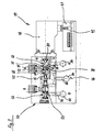
- FIG. 2 shows a structural unit 44 comprising a base plate 46, a pilot valve 48 and a valve unit 50.
- the latter has a block-shaped housing 52 which is anchored together with the pilot valve 48 on the base plate 46.
- This base plate 46 is traversed perpendicular to the plane of pressure-carrying ducts 54, via which the common supply or disposal may be made of several juxtaposed units 44.
- the base plate 46 is provided with branch channels 56, the pressure medium connections between the terminals of the valve unit 50 and the channels 54 produce.
- the base plate 46 has a through cavity 47, in which an electronic control device 49 is housed. This controls the pilot valve 48 electronically.
- the valve unit 50 has 5/2-way function and takes in its housing 52 two separate directional control valves 58 and 60 on.
- the directional control valve 58 is constructed identically to the directional control valve 10 according to FIG.
- the coaxial second directional control valve 60 has a slide 64, the piston 66 with the seat bodies 68 and 70 forms a so-called internal sealing valve.
- the collars of the seat bodies 68, 70 surrounding the valve openings 72 and 74 in contrast to the outer-sealing systems according to FIG. 1, are arranged on the mutually facing inner sides of these seat bodies 68, 70.
- the pistons 66 with their sealing disks 78, 80 are located between the two seat bodies 68, 70 and not outside thereof.
- the area ratios of the control pistons 82 and 84 or the seat bodies 68, 70 were retained and the assignment of the control pistons 82, 84 to the seat bodies 68, 70 changed.
- the seat body 68 is now adjacent to the small valve opening 72, while the control piston 84 with the large valve opening 74 is assigned to the seat body 70 in the smaller diameter control piston 82.
- both control pistons 82 and 84 are made in several parts with the slider 64.
- a plurality of control channels 90a-e are provided in the housing 52, regardless of the control.
- the control channel 90a provides a pressure medium connection between the control chamber 96, in which the two small control pistons 32, 82 are arranged together in the embodiment and the control channel 90b, which leads to the pilot valve 48.
- the leading to the outside of the valve unit 50 part of the pressure medium channel 90a is available only for manufacturing reasons and has no pressure-carrying function. He is closed for these reasons to the outside, for example, by a not shown plug.
- another control channel 90c connects the pilot valve 48 with a branch of the inlet-side pressure medium channel P, which opens into the slide bore 53 of the directional control valve 58, 60.
- control channel 90c the pilot valve 48 is supplied with pressure medium.
- a control channel 90d is provided, which leads from the pilot valve 48 to the return-side pressure medium channel of the directional control valve 60 designated R.
- the control channels 90b-d are substantially parallel to the slide bore 53rd
- Another control channel 90e is located on the control channels 90a-d opposite side of the slide bore 53 and connects the two outer control chambers 40 and 100 of the directional control valves 58 and 60 with each other. In addition, this control channel 90e also leads to the pilot valve 48th
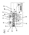
- the valve unit 50 shown in Figure 3 counteracts the pulse valve of Figure 2 as a switching valve with pressure medium return.
- the two-way valves 58 and 60 common control chamber 96 is acted upon by the control channels 90a and 90b permanently with operating pressure.
- the thereby on the control piston 32 and 82nd acting pressure force spends the two way valves 58, 60 in the illustrated basic position.
- the outer control chambers 40 and 100 of the two-way valves 58, 60 are also subjected to operating pressure. This is done by the pilot valve 48 via the control channel 90e.
- the pressure force caused by the control pistons 34 and 84 of the directional control valves 58 and 60 is greater than that of the smaller-diameter control pistons 32, 82 counterforce due to the different sized pressurized surfaces.
- the sealing rings 36 provided on these adjusting pistons 32 and 82 can be omitted without replacement.
- pressure build-up in the control chamber 96 can also take place via the guide gaps of these control pistons 32 and 82.
- the control channels 90a or 90b are not needed in this case.
- control chambers 40, 100 are relieved of pressure via the control channels 90d and 90e to the return side pressure medium channel R.
- the control chamber 96 which is still under operating pressure, together with the small control pistons 32, 82, return the directional control valves 58 and 60 to the basic position.
- the valve unit 50 acts in contrast to the bistable pulse valve of the embodiment of Figure 2 as a pure switching valve or monostable valve, in which permanently applied in at least one of the control chambers 40, 96, 100 operating pressure.
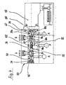
- the valve unit 50 can, as Figure 4 shows, also be designed as a reversing valve with mechanical reset.
- control chamber 96 is not pressurized medium.
- the control channels 90a and 90b become closed, for example by pressing a sealing plug.
- the control chamber 96 is vented by means of a connection to the pressure medium channel R or to the environment.
- a compression spring 102 is clamped. This pushes the two slides 26 and 64 of the directional control valves 58, 60 in the drawn basic position and is dimensioned so that the pressure forces generated in a possible pressurization of the control chambers 40, 100 of the control piston 34, 84 sufficient to overcome their bias.
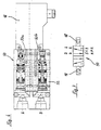
- Figure 5 shows a construction variant of a valve unit 50, in which the two-way valves 58 and 60 are not arranged coaxially, but parallel to each other in the housing 52.
- the longitudinal axes of the directional control valves 58, 60 are perpendicular to the support surface of the valve unit 50 on the base plate 46.
- the two-way valves 58, 60 are, apart from a two-part design of the slide bore 53a and 53b in the housing 52, identical to those of the previous - embodiments executed ,
- the slide bores 53a and 53b are continuous transverse bores in the housing 52 which are closed at one end by the base plate 46 and at the opposite second end by plugs 104.
- the pressure medium channels P and R are at right angles to the slide holes 53 a, b in the direction of the pilot valve 48. They connect the Schieberborhungen 53 a and 53 b together and end like a blind hole in the slide bore 53 a. The same applies to the control channels 90a and 90e leading to the control chambers 96a, b, 40 and 100.
- the pressure medium channels A and B are aligned perpendicular to the slide holes 53 a, b, but are not coupled to each other in contrast to the pressure medium channels P and R, but extend to opposite outer sides of the housing 52, where they pressed-in balls 106 are pressure-tightly sealed. Longitudinal channels 108 aligned parallel to the slide bores 53a, b establish a connection of the pressure medium passages A, B to peripheral connections 110. These terminals 110 may alternatively be provided on the base plate 46 or on the housing 52.
- the housing 52 is also relatively easy to produce due to the rectangular channel guide.
- FIG. 6 shows a valve unit 50 which is coupled to a pilot valve 48 and also has a two-part, parallel arrangement of the slide bores 53a, b.
- both slide bores 53a, b extend longitudinally and not transversely to the housing 52.
- the pressure medium connections A and B can thereby advantageously be arranged on the end face of the valve unit 50 facing away from the pilot valve 48.
- the various control channels which are indicated only schematically in FIG. 6 by dashed lines, are also guided in this variant in the longitudinal or transverse direction to the housing 52. In order to avoid repetitions regarding their function, reference is made to the previous explanations.
- valve units 50 with 5/2-way valve function which are constructed essentially of two of the invention underlying types of directional control valves 58, 60.
- All disclosed valve units 50 have a large number of identical parts and can be converted into one another at least partially by simple structural interventions.
- the construction principle on which the invention is based of directional valves 10, 58, 60 can therefore be extended to a valve-modular system, with the most diverse customer requirements can be realized without significant technical effort.
- FIG. 7 shows the circuit symbol for a valve unit 50, in the embodiment according to embodiment 2.
- the valve unit 50 has a total of five with P, R, A and B. designated terminals, which are numbered from 1 to 5 for the sake of simplicity.
- Terminal 1 or P is connected to a not shown pressure generator, terminal 2 to the consumer A, the terminals 3 and 5 with a return R and the terminal 4 to the second consumer B.
- terminal 1 is contacted with terminal 4 and terminal 2 to terminal 3.
- Terminal 3 is locked in switch position 1 and 5 connection in switch position 2.
Landscapes
- Engineering & Computer Science (AREA)
- Physics & Mathematics (AREA)
- Fluid Mechanics (AREA)
- Mechanical Engineering (AREA)
- General Engineering & Computer Science (AREA)
- Multiple-Way Valves (AREA)
- Mechanically-Actuated Valves (AREA)
- Fluid-Driven Valves (AREA)
Claims (8)
- Ensemble de distributeur pilote (50) comportant un premier distributeur pilote (10, 58) et un second distributeur pilote (60) comprenant chacun un boîtier (12, 52) dans lequel, dans le but de commander des liaisons de fluide sous pression, un obturateur respectif (26, 64) coopérant avec des corps de siège (18, 20, 68, 70) est guidé avec faculté de translation entre un canal à fluide sous pression (P) associé à l'alimentation, au moins un canal à fluide sous pression (R) associé au retour et au moins un canal à fluide sous pression (A, B) associé au dispositif consommateur,
caractérisé en ce que pour inverser le distributeur (10, 58, 60) de la position de base vers la position commutée ou inversement, l'obturateur (26, 64) est équipé de deux pistons de commande (32, 34, 82, 84) opposés l'un à l'autre et présentant des surfaces de piston de différentes tailles, une chambre de commande (38, 40, 96, 100) étant associée à chaque piston de commande (32, 34, 82, 84), les corps de siège (18, 20 et 68, 70) présentant des ouvertures de distribution (22, 24, 72, 74) de différentes tailles,
en ce que dans le premier distributeur (10, 58), dans le but de réaliser un système avec étanchement vers l'extérieur dans lequel les surfaces frontales des corps de siège (18, 20) détournées l'une de l'autre coopèrent avec l'obturateur (26), le corps de siège (18) qui commande une liaison à fluide sous pression entre les canaux à fluide sous pression (P) et (A) présente la grande ouverture de distribution (22) et se trouve au voisinage du piston de commande (32) présentant la petite surface de piston, et
en ce que dans le second distributeur (60), dans le but de réaliser un système avec étanchement vers l'intérieur dans lequel les surfaces frontales des corps de siège (68, 70) tournées l'une vers l'autre coopèrent avec l'obturateur (64), le corps de siège (68) qui commande une liaison à fluide sous pression entre les canaux à fluide sous pression (P) et (B) présente la petite ouverture de distribution (72) et se trouve au voisinage du piston de commande (82) présentant la petite surface de piston. - Ensemble de distributeur pilote selon la revendication 1, caractérisé en ce que les obturateurs (26, 64) sont agencés en alignement mutuel dans un perçage de coulissement commun.
- Ensemble de distributeur pilote selon la revendication 1, caractérisé en ce que les obturateurs (26, 64) sont agencés parallèlement l'un à l'autre dans deux perçages de coulissement.
- Ensemble de distributeur pilote selon l'une des revendications 1 à 3, caractérisé en ce que des canaux de commande (90a, 90b) sont prévus dans le boîtier commun (12, 52), qui établissent une liaison à fluide sous pression entre un distributeur pilote (48) et la chambre de commande (96) recevant les petits pistons de commande (32, 82), d'autres canaux de commande (90c) reliant le canal à fluide sous pression (P) côté alimentation au distributeur pilote (48), et en ce que des canaux de commande (90e) couplent le distributeur pilote (48) aux chambres de commande (40, 100) des grands pistons de commande (32, 34).
- Ensemble de distributeur pilote selon la revendication 4, caractérisé en ce que l'ensemble de distributeur (50) est réalisé sous forme de distributeur à impulsions dans lequel le distributeur pilote (48) sollicite par des impulsions de pression la chambre de commande (96) ou les chambres de commande (40, 100) en alternance via les canaux de commande (90b ou 90e).
- Ensemble de distributeur pilote selon la revendication 4, caractérisé en ce que l'ensemble distributeur (50) est réalisé sous forme de distributeur d'inversion susceptible d'être rappelé par le fluide sous pression et dans lequel le distributeur pilote (48) sollicite la chambre de commande (96) en permanence par une pression de commande, et en cas d'inversion, il sollicite les chambres de commande (40, 100) temporairement par une pression de commande.
- Ensemble de distributeur pilote selon la revendication 4, caractérisé en ce que l'ensemble distributeur (50) est réalisé sous forme de distributeur d'inversion susceptible d'être rappelé par voie mécanique, dans lequel la chambre de commande (96) est déchargée de pression et reçoit un ressort de compression (102) qui prend appui contre les deux petits pistons de commande (32, 82) et dont la force de compression s'oppose aux forces de pression engendrées par les chambres de commande (40, 100).
- Ensemble de distributeur pilote selon l'une des revendications 1 à 7, caractérisé en ce que l'ensemble distributeur (50) permet de piloter un dispositif consommateur pneumatique à double effet.
Applications Claiming Priority (2)
| Application Number | Priority Date | Filing Date | Title |
|---|---|---|---|
| DE1999109918 DE19909918A1 (de) | 1999-03-06 | 1999-03-06 | Vorsteuerbares Wegeventil |
| DE19909918 | 1999-03-06 |
Publications (3)
| Publication Number | Publication Date |
|---|---|
| EP1035331A2 EP1035331A2 (fr) | 2000-09-13 |
| EP1035331A3 EP1035331A3 (fr) | 2002-05-29 |
| EP1035331B1 true EP1035331B1 (fr) | 2007-01-10 |
Family
ID=7899949
Family Applications (1)
| Application Number | Title | Priority Date | Filing Date |
|---|---|---|---|
| EP19990126259 Expired - Lifetime EP1035331B1 (fr) | 1999-03-06 | 1999-12-31 | Distributeur piloté |
Country Status (2)
| Country | Link |
|---|---|
| EP (1) | EP1035331B1 (fr) |
| DE (2) | DE19909918A1 (fr) |
Families Citing this family (6)
| Publication number | Priority date | Publication date | Assignee | Title |
|---|---|---|---|---|
| DE10109206B4 (de) * | 2001-02-26 | 2004-12-09 | Rexroth Mecman Gmbh | Mehrwegeventil zum Schalten eines Druckmittelflusses mit paralleverlaufenden Ventilbohrungen |
| DE102004020794B4 (de) * | 2004-04-28 | 2006-02-09 | Bosch Rexroth Ag | Vorgesteuertes 4/3-Wegeventil |
| US20090301589A1 (en) * | 2004-12-15 | 2009-12-10 | Pili Roger R | Direct acting zero leak 4/3 tandem center neutral valve |
| DE102016225742A1 (de) * | 2016-12-21 | 2018-06-21 | Robert Bosch Gmbh | Ventilvorrichtung |
| CN110878847A (zh) * | 2019-12-13 | 2020-03-13 | 瑞立集团瑞安汽车零部件有限公司 | 一种流体阀取低输出装置 |
| EP3845767B1 (fr) * | 2019-12-30 | 2024-07-24 | Danfoss Power Solutions Aps | Groupe de soupapes |
Family Cites Families (5)
| Publication number | Priority date | Publication date | Assignee | Title |
|---|---|---|---|---|
| US3175581A (en) * | 1962-09-04 | 1965-03-30 | Modernair Corp | Multi-way poppet valve |
| US3608587A (en) * | 1969-08-06 | 1971-09-28 | Ross Operating Valve Co | Single spindle four-way valve |
| DE3322912A1 (de) * | 1983-06-25 | 1985-01-03 | Wabco Steuerungstechnik GmbH & Co, 3000 Hannover | Mehrwege-sitzventil |
| GB2168789B (en) * | 1984-12-24 | 1988-08-17 | Ross Operating Valve Co | Improved inline poppet valve |
| US5103866A (en) * | 1991-02-22 | 1992-04-14 | Foster Raymond K | Poppet valve and valve assemblies utilizing same |
-
1999
- 1999-03-06 DE DE1999109918 patent/DE19909918A1/de not_active Ceased
- 1999-12-31 DE DE59914148T patent/DE59914148D1/de not_active Expired - Lifetime
- 1999-12-31 EP EP19990126259 patent/EP1035331B1/fr not_active Expired - Lifetime
Also Published As
| Publication number | Publication date |
|---|---|
| DE19909918A1 (de) | 2000-09-14 |
| DE59914148D1 (de) | 2007-02-22 |
| EP1035331A2 (fr) | 2000-09-13 |
| EP1035331A3 (fr) | 2002-05-29 |
Similar Documents
| Publication | Publication Date | Title |
|---|---|---|
| DE60223341T2 (de) | Direkt angetriebenes Pneumatikventil mit luftunterstütztem Rückhub | |
| DE2543466B2 (de) | Fluidgesteuertes Ventil | |
| EP0374438A1 (fr) | Distributeur piloté | |
| EP1939461A2 (fr) | Vanne pneumatique modulaire à tiroir | |
| EP1035331B1 (fr) | Distributeur piloté | |
| DD232532A5 (de) | Mehrwege-tellerventil | |
| EP0921322B1 (fr) | Soupape de réglage pneumatique | |
| EP0686775B2 (fr) | Dispositif de vanne électropneumatique | |
| DE2926539C2 (de) | Regelventil für Fahrzeugbremsanlagen mit zwei Bremskreisen | |
| DE102021213469B3 (de) | Sicherheitsventileinrichtung | |
| EP0463394B1 (fr) | Distributeur à commande électromagnétique | |
| DE4011908A1 (de) | Mehrwegeventil | |
| DE19509578B4 (de) | Pneumatisches Wegeventil | |
| DE8533506U1 (de) | Tellerventil | |
| DE19841056A1 (de) | Impulsgesteuertes pneumatisches 4/2-Wegeventil | |
| DE19654254C2 (de) | Mehrfach-Sitzventil | |
| DE10116507B4 (de) | Ventilanordnung | |
| DE102022110517B4 (de) | Hybridwirkendes 3/2-Wege-(Magnet-)Ventil mit einem Eingang und zwei Ausgängen und Thermo- / Wärme-Management-Modul mit Ventil | |
| DE2929578A1 (de) | Notventileinrichtung in pneumatischen oder hydraulischen steuerungsanlagen | |
| WO2001004497A1 (fr) | Soupape a tiroir pilotee | |
| DE19713313A1 (de) | Steuerbare Ventileinrichtung | |
| WO2017121523A1 (fr) | Ensemble vanne électromagnétique, son utilisation et système | |
| DE2340304A1 (de) | Kombinierbares wegeventil | |
| DE102004023979B3 (de) | Vorgesteuertes Mehrwegeventil | |
| EP2140181B1 (fr) | Distributeur et ensemble soupape |
Legal Events
| Date | Code | Title | Description |
|---|---|---|---|
| PUAI | Public reference made under article 153(3) epc to a published international application that has entered the european phase |
Free format text: ORIGINAL CODE: 0009012 |
|
| AK | Designated contracting states |
Kind code of ref document: A2 Designated state(s): AT BE CH CY DE DK ES FI FR GB GR IE IT LI LU MC NL PT SE |
|
| AX | Request for extension of the european patent |
Free format text: AL;LT;LV;MK;RO;SI |
|
| PUAL | Search report despatched |
Free format text: ORIGINAL CODE: 0009013 |
|
| AK | Designated contracting states |
Kind code of ref document: A3 Designated state(s): AT BE CH CY DE DK ES FI FR GB GR IE IT LI LU MC NL PT SE |
|
| AX | Request for extension of the european patent |
Free format text: AL;LT;LV;MK;RO;SI |
|
| RIC1 | Information provided on ipc code assigned before grant |
Free format text: 7F 15B 13/042 A, 7F 15B 13/00 B, 7F 16K 11/044 B, 7F 16K 11/048 B, 7F 16K 31/122 B, 7F 15B 13/04 B |
|
| 17P | Request for examination filed |
Effective date: 20020911 |
|
| 17Q | First examination report despatched |
Effective date: 20021211 |
|
| AKX | Designation fees paid |
Designated state(s): DE FR GB IT SE |
|
| GRAP | Despatch of communication of intention to grant a patent |
Free format text: ORIGINAL CODE: EPIDOSNIGR1 |
|
| GRAS | Grant fee paid |
Free format text: ORIGINAL CODE: EPIDOSNIGR3 |
|
| GRAA | (expected) grant |
Free format text: ORIGINAL CODE: 0009210 |
|
| AK | Designated contracting states |
Kind code of ref document: B1 Designated state(s): DE FR GB IT SE |
|
| REG | Reference to a national code |
Ref country code: GB Ref legal event code: FG4D Free format text: NOT ENGLISH |
|
| REF | Corresponds to: |
Ref document number: 59914148 Country of ref document: DE Date of ref document: 20070222 Kind code of ref document: P |
|
| REG | Reference to a national code |
Ref country code: SE Ref legal event code: TRGR |
|
| GBV | Gb: ep patent (uk) treated as always having been void in accordance with gb section 77(7)/1977 [no translation filed] |
Effective date: 20070110 |
|
| ET | Fr: translation filed | ||
| PLBE | No opposition filed within time limit |
Free format text: ORIGINAL CODE: 0009261 |
|
| STAA | Information on the status of an ep patent application or granted ep patent |
Free format text: STATUS: NO OPPOSITION FILED WITHIN TIME LIMIT |
|
| PG25 | Lapsed in a contracting state [announced via postgrant information from national office to epo] |
Ref country code: GB Free format text: LAPSE BECAUSE OF FAILURE TO SUBMIT A TRANSLATION OF THE DESCRIPTION OR TO PAY THE FEE WITHIN THE PRESCRIBED TIME-LIMIT Effective date: 20070110 |
|
| 26N | No opposition filed |
Effective date: 20071011 |
|
| PGFP | Annual fee paid to national office [announced via postgrant information from national office to epo] |
Ref country code: SE Payment date: 20071220 Year of fee payment: 9 |
|
| PGFP | Annual fee paid to national office [announced via postgrant information from national office to epo] |
Ref country code: FR Payment date: 20071214 Year of fee payment: 9 |
|
| EUG | Se: european patent has lapsed | ||
| REG | Reference to a national code |
Ref country code: FR Ref legal event code: ST Effective date: 20090831 |
|
| PG25 | Lapsed in a contracting state [announced via postgrant information from national office to epo] |
Ref country code: FR Free format text: LAPSE BECAUSE OF NON-PAYMENT OF DUE FEES Effective date: 20081231 |
|
| PG25 | Lapsed in a contracting state [announced via postgrant information from national office to epo] |
Ref country code: SE Free format text: LAPSE BECAUSE OF NON-PAYMENT OF DUE FEES Effective date: 20090101 |
|
| PG25 | Lapsed in a contracting state [announced via postgrant information from national office to epo] |
Ref country code: IT Free format text: LAPSE BECAUSE OF NON-PAYMENT OF DUE FEES Effective date: 20071231 |
|
| PGFP | Annual fee paid to national office [announced via postgrant information from national office to epo] |
Ref country code: DE Payment date: 20110222 Year of fee payment: 12 |
|
| REG | Reference to a national code |
Ref country code: DE Ref legal event code: R119 Ref document number: 59914148 Country of ref document: DE Effective date: 20120703 |
|
| PG25 | Lapsed in a contracting state [announced via postgrant information from national office to epo] |
Ref country code: DE Free format text: LAPSE BECAUSE OF NON-PAYMENT OF DUE FEES Effective date: 20120703 |