EP1033798A1 - Überspannungsschutzeinrichtung - Google Patents
Überspannungsschutzeinrichtung Download PDFInfo
- Publication number
- EP1033798A1 EP1033798A1 EP00104059A EP00104059A EP1033798A1 EP 1033798 A1 EP1033798 A1 EP 1033798A1 EP 00104059 A EP00104059 A EP 00104059A EP 00104059 A EP00104059 A EP 00104059A EP 1033798 A1 EP1033798 A1 EP 1033798A1
- Authority
- EP
- European Patent Office
- Prior art keywords
- protection device
- spark
- surge protection
- horn
- connection
- Prior art date
- Legal status (The legal status is an assumption and is not a legal conclusion. Google has not performed a legal analysis and makes no representation as to the accuracy of the status listed.)
- Granted
Links
- 230000015556 catabolic process Effects 0.000 claims abstract description 24
- 239000004020 conductor Substances 0.000 claims description 4
- 230000001681 protective effect Effects 0.000 description 5
- 230000001012 protector Effects 0.000 description 2
- 230000001052 transient effect Effects 0.000 description 2
- 230000001960 triggered effect Effects 0.000 description 2
- 229910001080 W alloy Inorganic materials 0.000 description 1
- 238000006243 chemical reaction Methods 0.000 description 1
- 238000010276 construction Methods 0.000 description 1
- SBYXRAKIOMOBFF-UHFFFAOYSA-N copper tungsten Chemical compound [Cu].[W] SBYXRAKIOMOBFF-UHFFFAOYSA-N 0.000 description 1
- 239000012777 electrically insulating material Substances 0.000 description 1
- 238000005538 encapsulation Methods 0.000 description 1
- 230000033001 locomotion Effects 0.000 description 1
- 238000005259 measurement Methods 0.000 description 1
- 230000001105 regulatory effect Effects 0.000 description 1
- 230000035945 sensitivity Effects 0.000 description 1
- 238000009423 ventilation Methods 0.000 description 1
Images



Classifications
-
- H—ELECTRICITY
- H01—ELECTRIC ELEMENTS
- H01T—SPARK GAPS; OVERVOLTAGE ARRESTERS USING SPARK GAPS; SPARKING PLUGS; CORONA DEVICES; GENERATING IONS TO BE INTRODUCED INTO NON-ENCLOSED GASES
- H01T1/00—Details of spark gaps
- H01T1/20—Means for starting arc or facilitating ignition of spark gap
- H01T1/22—Means for starting arc or facilitating ignition of spark gap by the shape or the composition of the electrodes
-
- H—ELECTRICITY
- H01—ELECTRIC ELEMENTS
- H01T—SPARK GAPS; OVERVOLTAGE ARRESTERS USING SPARK GAPS; SPARKING PLUGS; CORONA DEVICES; GENERATING IONS TO BE INTRODUCED INTO NON-ENCLOSED GASES
- H01T4/00—Overvoltage arresters using spark gaps
- H01T4/10—Overvoltage arresters using spark gaps having a single gap or a plurality of gaps in parallel
-
- H—ELECTRICITY
- H01—ELECTRIC ELEMENTS
- H01T—SPARK GAPS; OVERVOLTAGE ARRESTERS USING SPARK GAPS; SPARKING PLUGS; CORONA DEVICES; GENERATING IONS TO BE INTRODUCED INTO NON-ENCLOSED GASES
- H01T4/00—Overvoltage arresters using spark gaps
- H01T4/10—Overvoltage arresters using spark gaps having a single gap or a plurality of gaps in parallel
- H01T4/12—Overvoltage arresters using spark gaps having a single gap or a plurality of gaps in parallel hermetically sealed
-
- H—ELECTRICITY
- H01—ELECTRIC ELEMENTS
- H01T—SPARK GAPS; OVERVOLTAGE ARRESTERS USING SPARK GAPS; SPARKING PLUGS; CORONA DEVICES; GENERATING IONS TO BE INTRODUCED INTO NON-ENCLOSED GASES
- H01T4/00—Overvoltage arresters using spark gaps
- H01T4/10—Overvoltage arresters using spark gaps having a single gap or a plurality of gaps in parallel
- H01T4/14—Arcing horns
Definitions
- the invention relates to an overvoltage protection device with a first spark horn having the first electrode, with a second spark horn second electrode, with an air breakdown spark gap effective between the spark horns and with a housing receiving the electrodes, the two spark horns being designed and arranged in relation to one another, that they diverge from a lower ignition area to their outer ends, so that the air breakdown spark gap starts from the ignition area expanded outside.
- At least one is an essential part of a surge protection device Spark gap that responds to a certain overvoltage, the response voltage and thus prevents that by such a surge protector protected area overvoltages occur that are greater than the pickup voltage the spark gap are.
- the surge protection device according to the invention two electrodes and one between the electrodes or their spark horns effective air breakdown spark gap.
- surge protective devices with an air breakdown spark gap there are surge protective devices with an air flashover spark gap in which a sliding discharge occurs when activated.
- Surge protection devices with an air breakdown spark gap have overvoltage protection devices with an air flashover spark gap the advantage of a higher one Surge current carrying capacity, but the disadvantage of a higher one - and not particularly constant - response voltage. Therefore there are already various surge protection devices proposed with an air breakdown spark gap which have been improved in response voltage.
- Air breakdown spark gaps have been realized in various ways, e.g. B. such that at least one sliding discharge between the spark horns triggering ignition aid has been provided, partially in the air breakdown spark gap protrudes, is web-like and made of plastic.
- An overvoltage protection device from which the invention is based is already out known from DE 44 02 615 C 2.
- the well-known surge protection device has two narrow electrodes, which are each angular and each have a spark horn and an angled connecting leg.
- the known surge protection device is characterized in that it due to the electrodes extending virtually in one plane, only a small one Has width.
- the known surge protection device has in any case a high surge current carrying capacity and a high one at the first response Line follow current extinguishing capacity. Problems always arise when there is a problem Arc seizes in one place, causing damage to the electrodes can.
- an overvoltage protection device is known from DE 196 04 947 C 1, which is essentially rotationally symmetrical.
- the two electrodes are identical and each have truncated cone-shaped spark horns, whereby an ignition bridge between the two facing ends of the spark horns to trigger a sliding discharge.
- This well-known surge protection device is also characterized by a high surge current carrying capacity and a high follow-up current extinguishing capacity.
- the disadvantage is that the known surge protective device has a relatively large overall height. Another The disadvantage is that when the spark gap is triggered, it is considerable Forces act on the extremely sensitive ignition bridge, causing damage to the Ignition bridge can lead.
- the object of the present invention is therefore an overvoltage protection device of the type in question to indicate the smallest possible height due to a high surge current carrying capacity and a high follow-up current extinguishing capacity distinguished.
- the surge protection device in which the previously derived and the stated problem is solved is first and for the most part characterized in that the first spark horn is frustoconical and the second spark horn is arranged concentrically around the first spark horn.
- the first electrode with the first spark horn is a central electrode represents, while the second electrode with the second spark horn one Represents outer electrode. Due to the concentric arrangement of the second spark horn around the first spark horn there is a around the central axis of the two electrodes - All or part - circumferential horn spark gap. It follows a circumferentially closed spark gap when the second spark horn circular and the surface of the second facing the first spark horn Spark horn is funnel-shaped.
- the second spark horn so that there are a plurality of concentric arranged around the first spark horn and spaced apart from each other having.
- a particularly preferred embodiment of the invention Surge protection device is characterized in that the second spark horn is in the form of an annular segment and that of the first spark horn facing surface of the second spark horn funnel-shaped is.
- the second spark horn preferably extends over an angle of approx. 210 ° to 270 °, especially over an angle of approx. 240 °.
- the surge protection device according to the invention in which the second spark horn is designed in the form of a circular segment, it is a those in which there is only a partial rotation around the central axis of the two electrodes Horn spark gap results.
- this is characterized by the central axis of the electrodes - wholly or preferably partially - circumferential horn spark gap due to a very high surge current carrying capacity and an equally high one Line follow current extinguishing capacity. Furthermore results from the concentric Arrangement of the second spark horn around the first spark horn is a very small one Overall height of the surge protection device according to the invention and a simple one Construction.
- a preferred embodiment of the surge protection device according to the invention is further characterized in that in the ignition area between the two spark horns at least one spark plug from an electrically insulating Material is provided.
- a sliding discharge is triggered via the ignition bridge, which, once addressed, at a relatively constant low response voltage an ignition of the air breakdown spark gap with a relatively high surge current carrying capacity leads. Since in the overvoltage protection device according to the invention Spark gap in contrast to the surge protection device known from DE 196 04 947 C 1 is not opened in the radial but in the axial direction, on the other hand, this leads to the fact that the mechanical Forces on the extremely sensitive ignition bridge are minimized.
- the ignition bridge is ring-shaped; so it is like the second Spark horn, arranged concentrically around the first spark horn.
- the ignition bridge consists of an extinguishing gas which emits when heated Plastic.
- the overvoltage protection device according to the invention is known per se Have a first connection area and a second connection area. Preferably it is provided in this connection that the first connection area and the second connection area on the same side of the surge protective device are located. This has the advantage that in the case of response the electromagnetic forces acting on the arc Support locomotion from the ignition area to the expanded horn area.
- the last described embodiment of the surge protection device according to the invention is preferably further characterized in that the electrodes have bores and / or through openings in the connection areas, in the connection areas beyond the connection areas connecting elements are provided, namely a PE connection element and a potential connection element, and preferably in a connection area, preferably in the for the potential connection element provided connection area, two connection options are provided.
- connection elements may be provided so that the overvoltage protection device can have a disk-like or pot-like shape as it were.
- the electrodes must be connected to connection elements be used in the area of the connection areas, for example screwed are. Otherwise, through openings in the electrodes ventilation can be implemented in a simple manner.
- both connection areas and thus both connection elements on the same Provided side it is recommended to be outside in the area of the connection areas at least one preferably wave-shaped web for enlargement the creepage distance between the connection areas.
- the second spark horn is circular segment shaped.
- the last described preferred embodiment of the surge protection device according to the invention is preferably additionally characterized by that the potential connection element on the opposite of the PE connection element Side of the two electrodes is provided and preferably further by that at least the second electrode and thus the second spark horn, preferably both electrodes and thus both spark horns symmetrically in relation is designed and arranged on the PE connection element.
- the housing can be a Have lower housing part and a housing cover, then preferably that Lower housing part and the housing cover screwed together and / or with each other can be glued. Otherwise, for reasons of protection against accidental contact, that the lower housing part and the housing cover nowhere the first electrode or contact the second electrode; is preferably between the first Electrode and the second electrode on the one hand and the lower housing part and the Housing cover on the other hand provided at least one insulating part and / or an air gap.
- a baffle at a distance from the ends of the spark horns provide against an arc in the event of the surge protector responding running.
- a baffle plate which is preferred - like the electrodes - made of a copper-tungsten alloy, can, by the way damage to the housing, which may be made of plastic, is also excluded become.
- the energy conversion in the gas space is due to the baffle plate influenced.
- the arc is divided into three by the baffle plate. Make it up two arcing areas and one current area in the baffle. Thereby there are two anode-cathode cases and additionally one overall reduced Arc because part of the current path runs in the baffle plate and does not generate plasma.
- the spark gap is preferably between an ignition electrode and one of the two electrodes is provided, so that only an additional electrode, namely the ignition electrode, is required.
- the ignition electrode can be realized in a simple manner in that they are from the housing and / or is formed by the baffle plate, it then being understood that the housing and / or the baffle plate each consist of electrically conductive material. Furthermore In this context, it must be ensured that neither the housing nor the The baffle plate is in electrically conductive contact with one of the electrodes. Of course is that if an "active" ignition aid is provided, a corresponding one Ignition circuit for the spark gap must be available.
- the surge protection device according to the invention a further improved line follow current extinguishing capacity can result in the housing being encapsulated in a pressure-tight manner.
- the housing from a lower housing part and one Housing cover, then it is recommended that the lower housing part and / or the housing cover, preferably the lower housing part on its side facing the housing cover Edge, with acting as pressure compensation openings, preferably radial extending slots.
- an overvoltage protection device 1 is shown, the first Electrode 2 with a first spark horn 3 and a second electrode 4 with a second spark horn 5. Between the first spark horn 3 and the second Spark horn 5 is an air breakdown spark gap 6.
- the two Electrodes 2, 4 are therefore spaced from one another and are not connected to one another.
- the overvoltage protection device 1 has the two electrodes 2, 4 receiving housing 7 on As can be seen in particular from Fig. 3, are the two spark horns 3, 5 designed and arranged to each other that they from a lower ignition area 8 of the air breakdown spark gap 6 each their outer ends 9, 10 diverge. This results in an outgoing from the ignition area 8, continuously expanding shape of the air breakdown spark gap 6.
- the air breakdown spark gap 6 V-shaped, with the opening angle of the air breakdown spark gap 6 is approximately 45 °. However, smaller opening angles (up to 10 °) or larger opening angles (up to 150 °) can be realized.
- the overvoltage protection device 1 thus has the one indicated in FIG. 3
- Center axis A has a rotationally symmetrical structure, the air breakdown spark gap 6 by the arrangement of the electrodes 2, 4 according to the invention is arranged concentrically around the central axis A and is open in the axial direction.
- the second spark horn 5 is like that second electrode 4 is annular.
- To realize the V-shaped widening Air breakdown spark gap 6 is the one facing the first spark horn 3 Surface of the second spark horn 5 formed like a funnel.
- an ignition land 11 which is used to trigger a sliding discharge serves.
- the level of the response voltage can be over the width of the Ignition bridge 11 and / or the height, d. H. about how far the ignition land 11 in the air breakdown spark gap 6 protrudes, adjust.
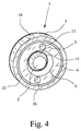
- the ignition bridge 11 itself is annular formed, which results from Fig. 4, and consists of a gas-emitting Plastic.
- the overvoltage protection element has 1 a first connection area 12 and a second connection area 13 on.
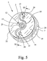
- the first connection area 12 and the second connection area 13 are on the provided the same side of the surge protection device 1; the side of the Surge protection device 11 on which the two connection areas 12, 13th are provided, the connection side is 14.
- the electrode 2 points in the first Connection area 12 has a bore 15 with an internal thread on electrode 4 has in the second connection area 13 two through openings 16, 17 which each, like the bore 15, are provided with an internal thread.
- 1 to 5 connecting elements, not shown, can be made using the bore 15 and the Through openings 16, 17 or with the help of in the bore 15 and in the through openings 16, 17 realized internal threads with electrodes 2 and 4 get connected.
- the overvoltage protection device is on the connection side 14 1 in the area of the connection areas 12, 13 at least one protruding Web 18 to increase the creepage distance between the connection areas 12, 13 is provided.
- the web 18 has a wave shape and separates the connection areas 12, 13 from each other.
- the housing is 7 encapsulated pressure-tight and filled with an extinguishing gas.
- the housing 7 itself, the both from an electrically insulating and from an electrically conductive material can exist, has a lower housing part 19 and a housing cover 20. Both components have a circular shape and are glued together.
- the first insulating part 21 has a circumferential one Wall section 23, which the second electrode 4 from the lower housing part 19th separates in the circumferential direction.
- the wall section 23 is from a plate-shaped Section 24 on which the second electrode 4 rests. Also lies a part of the first electrode 2 on the plate-shaped section 24 on the rest the ignition land 11 is also formed by the first insulating part 21. The ignition land 11 is thus formed in one piece with the first insulating part 21.
- the second insulating part 22 is arranged between a pin 25 of the first electrode 2 and the lower housing part 19.
- the outside of the second insulating part 22 also forms the connection side 14 of the overvoltage protection device 1.
- the second one Insulating part 22 has a circumferential wall section 26, which on the central Pin 25 of the first electrode 2 abuts and that of a plate-shaped section 27 is angled, the outside of which forms the connection side 14.
- the overvoltage protection device has 1 a baffle plate 30 which is spaced apart from the ends 9, 10 of the two electrodes 2, 4 is arranged.
- the baffle plate 30 is therefore opposite the orbiting air breakdown spark gap 6. It is not shown that over the Baffle plate 30 and one of the electrodes 2, 4 realizes a spark gap can be.
- the baffle plate 30 forms one ignition electrode while the other Ignition electrode is formed by one of the two electrodes 2, 4.
- the connection the baffle plate 30 to an ignition circuit can be connected to the ignition circuit with the lower housing part 19 or the housing cover 20, if these are made electrically conductive material consist of the baffle plate 30 both on the lower housing part 19 as well as on the housing cover 20.
- the surge protection device shown 1 consists of a very small number of components.
- the assembly of the Overvoltage protection device 1 can therefore be implemented quickly and easily become.
- the first insulating part is on the pin 25 of the first electrode 2 21 put on.
- the lower housing part 19 can already be placed on the second insulating part 22.
- the first insulating part 21 on the second insulating part 22 has the latter in the region of the openings 28, 29 sleeve-like projections 31, 32 on which the lower housing part 19 and the first insulating part 21 can be placed are and are aligned with the through openings 16, 17.
- a assembly composed of the aforementioned components 21, 19, 22 can according to Corresponding connection of the individual components to one another on the pin 25 the first electrode 2 are placed. Then the second electrode 4 used. Finally, the housing cover 20 with the baffle plate located therein 30 attached and connected to the lower housing part 19.
- the second spark horn 5 in an annular shape is applicable to the embodiment shown in FIGS. 6 and 7, that the second spark horn 5 is circular segment shaped; in the illustrated The second spark horn 5 extends over an exemplary embodiment Angle of approx. 240 °. Characterized in that in the embodiment shown in Figs. 6 and 7 the second overvoltage protection device 1 Spark horn 5 is not circular, but - only - formed in the shape of a circular segment is, in the second spark horn 5, viewed in the circumferential direction, one Interruption. In other words: in the exemplary embodiment according to FIGS.
- Overvoltage protection device 1 belonging connecting elements are not shown are the connection elements in the embodiment of FIGS. 6 and 7 shown; namely, a PE connection element 31 and a potential connection element are shown 32. Also in this embodiment, as in the embodiment 1 to 5, the two connection areas 12, 13 and thus that PE connection element 31 and the potential connection element 32 on the same side the overvoltage protection device 1 is provided, namely on the connection side 14.
- the two connection elements are, that is, the PE connection element 31 and the potential connection element 32, can 6 and 7 that the second spark horn 6 on the second connection area 13 and thus aligned with the potential connection elements 32 is.
- This also means that the area of the second Spark horn 5, which "does not exist as it were", ie the recess or the Interruption to the first connection area 12 and thus to the PE connection element 31 is aligned.
- FIGS. 6 and 7 show, the same applies to the exemplary embodiment shown in these figures an overvoltage protection device 1 according to the invention that the potential connection element 32 on the PE connection element 31 opposite Side of the two electrodes 2, 4 is provided.
- 6 and 7 show, that applies to the illustrated embodiment that both spark horns 3, 5 symmetrically are designed and arranged with respect to the PE connection element 31; this also applies to the design and arrangement in relation to the potential connection element 32.
- FIGS. 1 to 5 it has been pointed out that the housing is encapsulated in a pressure-tight manner and with a Extinguishing gas is filled. This does not apply to the exemplary embodiment according to FIGS. 6 and 7. Rather, it applies to this exemplary embodiment that the housing 7 has pressure equalization openings is provided.
- the lower housing part 19 is on its Housing cover 20 facing edge 33 with effective as pressure compensation openings, radially extending slots 34. In addition, neither can shown, axially extending slots may be provided.
- the second spark horn 5 is not in the form of a ring, but rather is only in the form of a ring segment, 6 results in a free space 35.
- the free space 35 can be used for Response of the overvoltage protection device 1 by the resulting Cool the arc generated plasma.
- the free space 35 is dimensioned so that in Connection with the entire cross section of all slots 34 of the "slow" pressure build-up in the free space 35 the plasma has time to cool down.
Landscapes
- Emergency Protection Circuit Devices (AREA)
Abstract
Description
- Fig. 1
- eine perspektivische Ansicht eines ersten Ausführungsbeispiels einer erfindungsgemäßen Überspannungsschutzeinrichtung, aufgeschnitten,
- Fig. 2
- eine weitere perspektivische Schnittansicht der Überspannungsschutzeinrichtung nach Fig. 1,
- Fig. 3
- einen Querschnitt durch die erfindungsgemäße Überspannungsschutzeinrichtung nach den Fig. 1 und 2, entlang der Schnittlinie III - III in Fig.5,
- Fig. 4
- eine perspektivische Draufsicht auf die Überspannungsschutzeinrichtung nach den Fig. 1 und 2, in geöffnetem Zustand,
- Fig. 5
- eine perspektivische Unteransicht der Überspannungsschutzeinrichtung nach den Fig. 1 und 2,
- Fig. 6
- eine Draufsicht auf ein zweites Ausführungsbeispiel einer erfindungsgemäßen Überspannungsschutzeinrichtung, in geöffnetem Zustand, und
- Fig. 7
- eine Unteransicht der Überspannungsschutzeinrichtung nach Fig. 6.
Claims (20)
- Überspannungsschutzeinrichtung (1), mit einer ein erstes Funkenhorn (3) aufweisenden ersten Elektrode (2), mit einer ein zweites Funkenhorn (5) aufweisenden zweiten Elektrode (4), mit einer zwischen den Funkenhörnern (3, 5) wirksamen Luft-Durchschlag-Funkenstrecke (6) und mit einem die Elektroden (2, 4) aufnehmenden Gehäuse (7), wobei die beiden Funkenhörner (3, 5) derart ausgebildet und zu einander angeordnet sind, daß sie von einem unteren Zündbereich (8) jeweils zu ihren äußeren Enden (9, 10) divergieren, so daß sich die Luft-Durchschlag-Funkenstrekke (6) ausgehend vom Zündbereich (8) nach außen erweitert, dadurch gekennzeichnet, daß das erste Funkenhorn (3) kegelstumpfförmig ausgebildet und das zweite Funkenhorn (5) konzentrisch um das erste Funkenhorn (3) herum angeordnet ist.
- Überspannungsschutzeinrichtung nach Anspruch 1, dadurch gekennzeichnet, daß das zweite Funkenhorn (5) kreisringförmig ausgebildet und die dem ersten Funkenhorn (3) zugewandte Fläche des zweiten Funkenhorns (5) trichterstumpfartig ausgebildet ist.
- Überspannungsschutzeinrichtung nach Anspruch 1, dadurch gekennzeichnet, daß das zweite Funkenhorn (5) kreisringsegmentförmig ausgebildet und die dem ersten Funkenhorn (3) zugewandte Fläche des zweiten Funkenhorns (5) trichterstumpfartig ausgebildet ist.
- Überspannungsschutzeinrichtung nach Anspruch 3, dadurch gekennzeichnet, daß sich das zweite Funkenhorn (5) über einen Winkel von ca. 210° bis 270° erstreckt, vorzugsweise über einen Winkel von ca. 240°.
- Überspannungsschutzeinrichtung nach einem der Ansprüche 1 bis 4, dadurch gekennzeichnet, daß im Zündbereich (8) zwischen den beiden Funkenhörnern (3, 5) wenigstens ein Zündsteg (11) zur Auslösung einer Gleitentladung vorgesehen ist und vorzugsweise der Zündsteg (8) ringförmig ausgebildet ist und/oder aus einem gasabgebenden Kunststoff besteht.
- Überspannungsschutzeinrichtung einem der Ansprüche 1 bis 5, mit einem ersten Anschlußbereich und mit einem zweiten Anschlußbereich, dadurch gekennzeichnet, daß der erste Anschlußbereich (12) und der zweite Anschlußbereich (13) auf der gleichen Seite der Überspannungsschutzeinrichtung (1) vorgesehen sind.
- Überspannungsschutzeinrichtung nach Anspruch 6, dadurch gekennzeichnet, daß die Elektroden (2, 4) in den Anschlußbereichen (12, 13) Bohrungen (15) und/oder Durchgangsöffnungen (16, 17) aufweisen, in den Anschlußbereichen (12, 13) über die Anschlußbereiche (12, 13) hinausragende Anschlußelemente vorgesehen sind, nämlich ein PE-Anschlußelement (31) und ein Potential-Anschlußelement (32), und vorzugsweise in einem Anschlußbereich (13), vorzugsweise in dem für das Potential-Anschlußelement (32) vorgesehenen Anschlußbereich (13), zwei Anschlußmöglichkeiten vorgesehen sind.
- Überspannungsschutzeinrichtung nach Anspruch 6 oder 7, dadurch gekennzeichnet, daß außenseitig im Bereich der Anschlußbereiche (12, 13) wenigstens ein abstehender, vorzugsweise wellenförmig ausgebildeter Steg (18) zur Vergrößerung der Kriechstrecke zwischen den Anschlußbereichen (12, 13) vorgesehen ist.
- Überspannungsschutzeinrichtung nach Anspruch 3 und einem der Ansprüche 6 bis 8, dadurch gekennzeichnet, daß das zweite Funkenhorn (5) auf den zweiten Anschlußbereich (13) und damit auf das Potential-Anschlußelement (32) ausgerichtet ist.
- Überspannungsschutzeinrichtung nach Anspruch 9, dadurch gekennzeichnet, daß das Potential-Anschlußelement (32) auf der dem PE-Anschlußelement (31) gegenüberliegenden Seite der beiden Elektroden (2, 4) vorgesehen ist.
- Überspannungsschutzeinrichtung nach Anspruch 10, dadurch gekennzeichnet, daß wenigstens die zweite Elektrode und damit das zweite Funkenhorn, vorzugsweise beide Elektroden (2, 4) und damit beide Funkenhörner (5, 3) symmetrisch in bezug auf das PE-Anschlußelement (31) ausgeführt und angeordnet ist bzw. sind.
- Überspannungsschutzeinrichtung nach einem der Ansprüche 1 bis 11, dadurch gekennzeichnet, daß das Gehäuse (7) druckdicht gekapselt und vorzugsweise mit einem Löschgas gefüllt ist.
- Überspannungsschutzeinrichtung einem der Ansprüche 1 bis 12, dadurch gekennzeichnet, daß das Gehäuse (7) ein Gehäuseunterteil (19) und einen Gehäusedeckel (20) aufweist und vorzugsweise das Gehäuseunterteil (19) und der Gehäusedeckel (20) miteinander verschraubt und/oder miteinander verklebt sind.
- Überspannungsschutzeinrichtung nach Anspruch 13, dadurch gekennzeichnet, daß das Gehäuseunterteil (19) und der Gehäusedeckel (20) an keiner Stelle die erste Elektrode (2) oder die zweite Elektrode (4) kontaktieren und vorzugsweise zwischen der ersten Elektrode (2) und der zweiten Elektrode (4) einerseits sowie dem Gehäuseunterteil (19) und dem Gehäusedeckel (20) andererseits wenigstens ein Isolierteil (21, 22) und/oder ein Luftspalt vorgesehen ist.
- Überspannungsschutzeinrichtung nach einem der Ansprüche 5 bis 13 und nach Anspruch 14, dadurch gekennzeichnet, daß der Zündsteg (11) einstückig mit dem Isolierteil (21) ausgebildet ist.
- Überspannungsschutzeinrichtung einem der Ansprüche 1 bis 15, dadurch gekennzeichnet, daß beabstandet zu den Enden (9, 10) der Funkenhörner (3, 5) eine Prallplatte (30) vorgesehen ist, die vorzugsweise im Gehäusedeckel (20) angeordnet ist.
- Überspannungsschutzeinrichtung nach einem der Ansprüche 1 bis 16, dadurch gekennzeichnet, daß im Bereich der Luft-Durchschlag-Funkenstrecke (6) und zusätzlich zu dieser eine Zündfunkenstrecke vorgesehen ist und vorzugsweise die Zündfunkenstrecke zwischen einer Zündelektrode und einer der beiden Elektroden (2, 4) vorgesehen ist.
- Überspannungsschutzeinrichtung nach Anspruch 17, dadurch gekennzeichnet, daß das Gehäuse (7) oder/und die Prallplatte (30) aus elektrisch leitendem Material oder/und von der Prallplatte (30) gebildet ist.
- Überspannungsschutzeinrichtung nach einem der Ansprüche 1 bis 11 oder nach einem der Ansprüche 13 bis 18, dadurch gekennzeichnet, daß das Gehäuse (7) mit Druckausgleichsöffnungen versehen ist.
- Überspannungsschutzeinrichtung nach Anspruch 13, ggf. nach einem der Ansprüche 14 bis 18 und nach Anspruch 19, dadurch gekennzeichnet, daß das Gehäuseunterteil oder/und der Gehäusedeckel, vorzugsweise das Gehäuseunterteil (19) an seinem dem Gehäusedeckel (20) zugewandten Rand (23), mit als Druckausgleichsöffnungen wirkenden, vorzugsweise radial verlaufenden Schlitzen (34) versehen ist.
Applications Claiming Priority (6)
| Application Number | Priority Date | Filing Date | Title |
|---|---|---|---|
| DE19909378 | 1999-03-04 | ||
| DE19909378 | 1999-03-04 | ||
| DE19914312 | 1999-03-29 | ||
| DE19914312 | 1999-03-29 | ||
| DE19951857 | 1999-10-27 | ||
| DE19951857 | 1999-10-27 |
Publications (2)
| Publication Number | Publication Date |
|---|---|
| EP1033798A1 true EP1033798A1 (de) | 2000-09-06 |
| EP1033798B1 EP1033798B1 (de) | 2005-01-26 |
Family
ID=27219009
Family Applications (1)
| Application Number | Title | Priority Date | Filing Date |
|---|---|---|---|
| EP00104059A Expired - Lifetime EP1033798B1 (de) | 1999-03-04 | 2000-02-28 | Überspannungsschutzeinrichtung |
Country Status (6)
| Country | Link |
|---|---|
| US (1) | US6566813B1 (de) |
| EP (1) | EP1033798B1 (de) |
| CN (1) | CN100338835C (de) |
| AT (1) | ATE288143T1 (de) |
| DE (2) | DE10008764A1 (de) |
| ES (1) | ES2237360T3 (de) |
Families Citing this family (22)
| Publication number | Priority date | Publication date | Assignee | Title |
|---|---|---|---|---|
| DE20020771U1 (de) * | 2000-02-22 | 2001-02-15 | Dehn & Soehne | Druckfest gekapselte Funkenstreckenanordnung zum Ableiten von schädlichen Störgrößen durch Überspannung |
| DE10060426B4 (de) * | 2000-11-24 | 2004-04-15 | Dehn + Söhne Gmbh + Co. Kg | Gekapselter Überspannungsableiter mit mindestens einer Funkenstrecke |
| DE10118210B4 (de) * | 2001-04-11 | 2012-02-23 | Dehn + Söhne Gmbh + Co. Kg | Gekapselter Überspannungsableiter mit einer Funkenstreckenanordnung |
| EP1338064B1 (de) | 2000-11-28 | 2011-09-28 | Dehn + Söhne Gmbh + Co Kg | Kompaktanordnung für mehrpolige stossstromfeste überspannungsableiter sowie gekapaelter überspannungsableiter hierfür |
| DE10120563A1 (de) * | 2001-04-03 | 2002-11-07 | Phoenix Contact Gmbh & Co | Überspannungsschutzelement und Überspannungsschutzeinrichtung |
| DE50211845D1 (de) * | 2001-08-01 | 2008-04-17 | Dehn & Soehne | Gekapselter überspannungsableiter auf funkenstreckenbasis |
| DE10140950B4 (de) * | 2001-08-01 | 2006-10-19 | Dehn + Söhne Gmbh + Co. Kg | Gekapselter Überspannungsableiter auf Funkenstreckenbasis |
| ATE391355T1 (de) * | 2001-08-21 | 2008-04-15 | Dehn & Soehne | Gekapselter, netzfolgestrom begrenzender überspannungsableiter auf funkenstreckenbasis |
| DE10164025B4 (de) * | 2001-08-21 | 2005-08-25 | Dehn + Söhne Gmbh + Co. Kg | Gekapselter, Netzfolgestrom begrenzender Überspannungsableiter auf Funkenstreckenbasis |
| CN1552117B (zh) * | 2001-09-02 | 2010-06-09 | 菲尼克斯电气公司 | 过电压保护装置 |
| DE10231431B4 (de) * | 2002-07-11 | 2014-03-20 | Dehn + Söhne Gmbh + Co. Kg | Gekapselter, druckfester Überspannungsableiter mit einer Funkenstrecke |
| US20040047107A1 (en) * | 2002-09-06 | 2004-03-11 | Chih-Chung Hsu | ESD protection circuit for touch button |
| DE102006048977B4 (de) * | 2005-05-30 | 2017-02-23 | Dehn + Söhne Gmbh + Co. Kg | Gekapselte, druckfest ausgeführte, nicht hermetisch dichte, rotationssymmetrische Hochleistungsfunkenstrecke |
| DE102005024658B4 (de) * | 2005-05-30 | 2007-02-15 | Dehn + Söhne Gmbh + Co. Kg | Gekapselte, druckfest ausgeführte, nicht hermetisch dichte, rotationssymmetrische Hochleistungsfunkenstrecke |
| DE102006020129A1 (de) | 2006-03-09 | 2007-09-13 | Dehn + Söhne Gmbh + Co. Kg | Gakapselte, druckfest ausgeführte, nicht hermetisch dichte, grundkonstruktiv rotationssymmetrische Hochleistungsfunkenstrecke |
| EP2080253B1 (de) * | 2006-10-17 | 2010-10-13 | Dehn + Söhne GmbH + Co. KG | Gekapselte, druckfest ausgeführte, nicht hermetisch dichte, rotationssymmetrische hochleistungsfunkenstrecke |
| DE102007015930A1 (de) | 2007-01-04 | 2008-07-10 | Dehn + Söhne Gmbh + Co. Kg | Gekapselte, druckfest ausgeführte, nicht hermetisch dichte, rotationssymmetrische Hochleistungsfunkenstrecke |
| DE102007015931A1 (de) | 2007-01-04 | 2008-07-10 | Dehn + Söhne Gmbh + Co. Kg | Gekapselte, druckfest ausgeführte, nicht hermetisch dichte, rotationssymmetrische Hochleistungsfunkenstrecke |
| DE102007015932A1 (de) | 2007-01-04 | 2008-07-10 | Dehn + Söhne Gmbh + Co. Kg | Gekapselte, druckfest ausgeführte, nicht hermetisch dichte Hochleistungsfunkenstrecke |
| ES2341212B1 (es) * | 2008-12-12 | 2011-05-31 | Fanox Electronic, S.L. | Supresor de energia. |
| CN102738785B (zh) * | 2011-04-15 | 2015-07-22 | 上海电科电器科技有限公司 | 过电压保护装置的放电模块 |
| CN102738707B (zh) * | 2011-04-15 | 2014-07-23 | 上海电科电器科技有限公司 | 过电压保护装置 |
Citations (4)
| Publication number | Priority date | Publication date | Assignee | Title |
|---|---|---|---|---|
| DE3910435A1 (de) * | 1989-02-25 | 1990-08-30 | Phoenix Elekt | Ueberspannungsschutzgeraet |
| DE4141681A1 (de) * | 1991-12-17 | 1993-07-29 | Phoenix Contact Gmbh & Co | Ueberspannungsschutzelement |
| DE4402615A1 (de) * | 1993-05-31 | 1994-12-08 | Phoenix Contact Gmbh & Co | Überspannungsschutzelement |
| DE19604947C1 (de) * | 1996-02-10 | 1997-07-10 | Dehn & Soehne | Verfahren zur Beeinflussung des Folgestromlöschvermögens von Funkenstreckenanordnungen und Funkenstreckenanordnungen hierfür |
Family Cites Families (9)
| Publication number | Priority date | Publication date | Assignee | Title |
|---|---|---|---|---|
| US2628322A (en) * | 1951-11-23 | 1953-02-10 | Joslyn Mfg & Supply Co | Lightning arrester |
| US3064156A (en) * | 1960-12-14 | 1962-11-13 | Ralph R Pittman | Excess-voltage protective device |
| US4056753A (en) * | 1976-02-13 | 1977-11-01 | Kabushiki Kaisha Sankosha | Overvoltage protecting element |
| DE3101354C2 (de) * | 1981-01-17 | 1984-11-29 | Dehn + Söhne GmbH + Co KG, 8500 Nürnberg | Funkenstrecke für die Begrenzung von Überspannungen |
| US4546402A (en) * | 1983-08-29 | 1985-10-08 | Joslyn Mfg. And Supply Co. | Hermetically sealed gas tube surge arrester |
| US5224013A (en) * | 1990-12-26 | 1993-06-29 | Tii Industries Inc. | Miniature station protector modules |
| DE4447567B4 (de) | 1993-05-31 | 2019-01-03 | Phoenix Contact Gmbh & Co. Kg | Überspannungsschutzelement |
| ES2148390T3 (es) * | 1994-10-07 | 2000-10-16 | Phoenix Contact Gmbh & Co | Elemento de proteccion contra sobretension. |
| US5768082A (en) * | 1995-09-29 | 1998-06-16 | Siemens Aktiengesellschaft | Gas-filled surge voltage protector |
-
2000
- 2000-02-26 DE DE10008764A patent/DE10008764A1/de not_active Ceased
- 2000-02-28 AT AT00104059T patent/ATE288143T1/de active
- 2000-02-28 EP EP00104059A patent/EP1033798B1/de not_active Expired - Lifetime
- 2000-02-28 ES ES00104059T patent/ES2237360T3/es not_active Expired - Lifetime
- 2000-02-28 DE DE50009317T patent/DE50009317D1/de not_active Expired - Lifetime
- 2000-03-03 CN CNB001038559A patent/CN100338835C/zh not_active Expired - Fee Related
- 2000-03-06 US US09/519,423 patent/US6566813B1/en not_active Expired - Lifetime
Patent Citations (4)
| Publication number | Priority date | Publication date | Assignee | Title |
|---|---|---|---|---|
| DE3910435A1 (de) * | 1989-02-25 | 1990-08-30 | Phoenix Elekt | Ueberspannungsschutzgeraet |
| DE4141681A1 (de) * | 1991-12-17 | 1993-07-29 | Phoenix Contact Gmbh & Co | Ueberspannungsschutzelement |
| DE4402615A1 (de) * | 1993-05-31 | 1994-12-08 | Phoenix Contact Gmbh & Co | Überspannungsschutzelement |
| DE19604947C1 (de) * | 1996-02-10 | 1997-07-10 | Dehn & Soehne | Verfahren zur Beeinflussung des Folgestromlöschvermögens von Funkenstreckenanordnungen und Funkenstreckenanordnungen hierfür |
Also Published As
| Publication number | Publication date |
|---|---|
| CN1267111A (zh) | 2000-09-20 |
| CN100338835C (zh) | 2007-09-19 |
| ES2237360T3 (es) | 2005-08-01 |
| US6566813B1 (en) | 2003-05-20 |
| DE10008764A1 (de) | 2000-09-28 |
| DE50009317D1 (de) | 2005-03-03 |
| ATE288143T1 (de) | 2005-02-15 |
| EP1033798B1 (de) | 2005-01-26 |
Similar Documents
| Publication | Publication Date | Title |
|---|---|---|
| EP1033798B1 (de) | Überspannungsschutzeinrichtung | |
| DE10338835B4 (de) | Überspannungsschutzeinrichtung | |
| DE2738077A1 (de) | Fehlersichere einrichtung mit mehreren funktionen fuer ueberspannungs- schutzvorrichtungen | |
| DE2740695A1 (de) | Funkenstreckenabsicherung | |
| DE4402615C2 (de) | Überspannungsschutzelement | |
| DE4141681C2 (de) | Überspannungsschutzelement | |
| EP0789434A1 (de) | Verfahren zur Beeinflussung des Folgestromlöschvermögens von Funkenstreckenanordnungen und Funkenstreckenanordnungen hierfür | |
| EP1423894B1 (de) | Überspannungsschutzeinrichtung | |
| EP1456921B1 (de) | Überspannungsschutzeinrichtung | |
| EP1283575B2 (de) | Störlichtbogengeschütztes elektrisches Bauteil | |
| EP1461852B1 (de) | Mehrpoliges überspannungsschutzsystem und verfahren zum sicheren betrieb eines mehrpoligen überspannungsschutzsystems | |
| EP1692751B1 (de) | Überspannungsschutzeinrichtung | |
| DE10146728B4 (de) | Überspannungsschutzeinrichtung | |
| DE4141682C2 (de) | Überspannungsschutzelement | |
| DE4244051C2 (de) | Überspannungsschutzelement | |
| EP1226638B1 (de) | Überspannungsschutzeinrichtung | |
| DE3910435C2 (de) | ||
| EP0635919B1 (de) | Überspannungsschutzelement | |
| DE4447567B4 (de) | Überspannungsschutzelement | |
| DE10040603B4 (de) | Überspannungsschutzeinrichtung | |
| DE10212697A1 (de) | Überspannungsschutzeinrichtung | |
| DE10120563A1 (de) | Überspannungsschutzelement und Überspannungsschutzeinrichtung | |
| DE202005008085U1 (de) | Überspannungsschutzeinrichtung | |
| DE29622886U1 (de) | Funkenstreckenanordnung |
Legal Events
| Date | Code | Title | Description |
|---|---|---|---|
| PUAI | Public reference made under article 153(3) epc to a published international application that has entered the european phase |
Free format text: ORIGINAL CODE: 0009012 |
|
| AK | Designated contracting states |
Kind code of ref document: A1 Designated state(s): AT BE CH CY DE DK ES FI FR GB GR IE IT LI LU MC NL PT SE |
|
| AX | Request for extension of the european patent |
Free format text: AL;LT;LV;MK;RO;SI |
|
| 17P | Request for examination filed |
Effective date: 20001202 |
|
| AKX | Designation fees paid |
Free format text: AT BE CH CY DE DK ES FI FR GB GR IE IT LI LU MC NL PT SE |
|
| RAP1 | Party data changed (applicant data changed or rights of an application transferred) |
Owner name: PHOENIX CONTACT GMBH & CO. KG |
|
| 17Q | First examination report despatched |
Effective date: 20030704 |
|
| GRAP | Despatch of communication of intention to grant a patent |
Free format text: ORIGINAL CODE: EPIDOSNIGR1 |
|
| GRAS | Grant fee paid |
Free format text: ORIGINAL CODE: EPIDOSNIGR3 |
|
| GRAA | (expected) grant |
Free format text: ORIGINAL CODE: 0009210 |
|
| AK | Designated contracting states |
Kind code of ref document: B1 Designated state(s): AT BE CH CY DE DK ES FI FR GB GR IE IT LI LU MC NL PT SE |
|
| PG25 | Lapsed in a contracting state [announced via postgrant information from national office to epo] |
Ref country code: IT Free format text: LAPSE BECAUSE OF FAILURE TO SUBMIT A TRANSLATION OF THE DESCRIPTION OR TO PAY THE FEE WITHIN THE PRESCRIBED TIME-LIMIT;WARNING: LAPSES OF ITALIAN PATENTS WITH EFFECTIVE DATE BEFORE 2007 MAY HAVE OCCURRED AT ANY TIME BEFORE 2007. THE CORRECT EFFECTIVE DATE MAY BE DIFFERENT FROM THE ONE RECORDED. Effective date: 20050126 Ref country code: IE Free format text: LAPSE BECAUSE OF FAILURE TO SUBMIT A TRANSLATION OF THE DESCRIPTION OR TO PAY THE FEE WITHIN THE PRESCRIBED TIME-LIMIT Effective date: 20050126 |
|
| REG | Reference to a national code |
Ref country code: GB Ref legal event code: FG4D Free format text: NOT ENGLISH |
|
| REG | Reference to a national code |
Ref country code: CH Ref legal event code: EP |
|
| REG | Reference to a national code |
Ref country code: IE Ref legal event code: FG4D Free format text: GERMAN |
|
| PG25 | Lapsed in a contracting state [announced via postgrant information from national office to epo] |
Ref country code: CY Free format text: LAPSE BECAUSE OF FAILURE TO SUBMIT A TRANSLATION OF THE DESCRIPTION OR TO PAY THE FEE WITHIN THE PRESCRIBED TIME-LIMIT Effective date: 20050228 Ref country code: MC Free format text: LAPSE BECAUSE OF NON-PAYMENT OF DUE FEES Effective date: 20050228 |
|
| REF | Corresponds to: |
Ref document number: 50009317 Country of ref document: DE Date of ref document: 20050303 Kind code of ref document: P |
|
| PG25 | Lapsed in a contracting state [announced via postgrant information from national office to epo] |
Ref country code: GR Free format text: LAPSE BECAUSE OF FAILURE TO SUBMIT A TRANSLATION OF THE DESCRIPTION OR TO PAY THE FEE WITHIN THE PRESCRIBED TIME-LIMIT Effective date: 20050426 Ref country code: DK Free format text: LAPSE BECAUSE OF FAILURE TO SUBMIT A TRANSLATION OF THE DESCRIPTION OR TO PAY THE FEE WITHIN THE PRESCRIBED TIME-LIMIT Effective date: 20050426 |
|
| REG | Reference to a national code |
Ref country code: SE Ref legal event code: TRGR |
|
| GBT | Gb: translation of ep patent filed (gb section 77(6)(a)/1977) |
Effective date: 20050420 |
|
| REG | Reference to a national code |
Ref country code: CH Ref legal event code: NV Representative=s name: KELLER & PARTNER PATENTANWAELTE AG |
|
| REG | Reference to a national code |
Ref country code: ES Ref legal event code: FG2A Ref document number: 2237360 Country of ref document: ES Kind code of ref document: T3 |
|
| REG | Reference to a national code |
Ref country code: IE Ref legal event code: FD4D |
|
| PLBE | No opposition filed within time limit |
Free format text: ORIGINAL CODE: 0009261 |
|
| STAA | Information on the status of an ep patent application or granted ep patent |
Free format text: STATUS: NO OPPOSITION FILED WITHIN TIME LIMIT |
|
| ET | Fr: translation filed | ||
| 26N | No opposition filed |
Effective date: 20051027 |
|
| PG25 | Lapsed in a contracting state [announced via postgrant information from national office to epo] |
Ref country code: PT Free format text: LAPSE BECAUSE OF NON-PAYMENT OF DUE FEES Effective date: 20050626 |
|
| REG | Reference to a national code |
Ref country code: FR Ref legal event code: PLFP Year of fee payment: 16 |
|
| REG | Reference to a national code |
Ref country code: CH Ref legal event code: PCAR Free format text: NEW ADDRESS: EIGERSTRASSE 2 POSTFACH, 3000 BERN 14 (CH) |
|
| PGFP | Annual fee paid to national office [announced via postgrant information from national office to epo] |
Ref country code: CH Payment date: 20150220 Year of fee payment: 16 Ref country code: FI Payment date: 20150224 Year of fee payment: 16 Ref country code: NL Payment date: 20150220 Year of fee payment: 16 Ref country code: LU Payment date: 20150223 Year of fee payment: 16 |
|
| PGFP | Annual fee paid to national office [announced via postgrant information from national office to epo] |
Ref country code: AT Payment date: 20150224 Year of fee payment: 16 Ref country code: FR Payment date: 20150223 Year of fee payment: 16 Ref country code: GB Payment date: 20150220 Year of fee payment: 16 Ref country code: SE Payment date: 20150220 Year of fee payment: 16 |
|
| PGFP | Annual fee paid to national office [announced via postgrant information from national office to epo] |
Ref country code: BE Payment date: 20150220 Year of fee payment: 16 |
|
| PGFP | Annual fee paid to national office [announced via postgrant information from national office to epo] |
Ref country code: ES Payment date: 20160201 Year of fee payment: 17 |
|
| PG25 | Lapsed in a contracting state [announced via postgrant information from national office to epo] |
Ref country code: BE Free format text: LAPSE BECAUSE OF NON-PAYMENT OF DUE FEES Effective date: 20160229 |
|
| PGFP | Annual fee paid to national office [announced via postgrant information from national office to epo] |
Ref country code: DE Payment date: 20160422 Year of fee payment: 17 |
|
| PG25 | Lapsed in a contracting state [announced via postgrant information from national office to epo] |
Ref country code: LU Free format text: LAPSE BECAUSE OF NON-PAYMENT OF DUE FEES Effective date: 20160228 |
|
| REG | Reference to a national code |
Ref country code: CH Ref legal event code: PL |
|
| REG | Reference to a national code |
Ref country code: AT Ref legal event code: MM01 Ref document number: 288143 Country of ref document: AT Kind code of ref document: T Effective date: 20160228 |
|
| GBPC | Gb: european patent ceased through non-payment of renewal fee |
Effective date: 20160228 |
|
| PG25 | Lapsed in a contracting state [announced via postgrant information from national office to epo] |
Ref country code: CH Free format text: LAPSE BECAUSE OF NON-PAYMENT OF DUE FEES Effective date: 20160229 Ref country code: LI Free format text: LAPSE BECAUSE OF NON-PAYMENT OF DUE FEES Effective date: 20160229 Ref country code: FI Free format text: LAPSE BECAUSE OF NON-PAYMENT OF DUE FEES Effective date: 20160228 |
|
| REG | Reference to a national code |
Ref country code: SE Ref legal event code: EUG |
|
| REG | Reference to a national code |
Ref country code: NL Ref legal event code: MM Effective date: 20160301 |
|
| REG | Reference to a national code |
Ref country code: FR Ref legal event code: ST Effective date: 20161028 |
|
| PG25 | Lapsed in a contracting state [announced via postgrant information from national office to epo] |
Ref country code: AT Free format text: LAPSE BECAUSE OF NON-PAYMENT OF DUE FEES Effective date: 20160228 Ref country code: SE Free format text: LAPSE BECAUSE OF NON-PAYMENT OF DUE FEES Effective date: 20160301 |
|
| PG25 | Lapsed in a contracting state [announced via postgrant information from national office to epo] |
Ref country code: FR Free format text: LAPSE BECAUSE OF NON-PAYMENT OF DUE FEES Effective date: 20160229 Ref country code: GB Free format text: LAPSE BECAUSE OF NON-PAYMENT OF DUE FEES Effective date: 20160228 Ref country code: NL Free format text: LAPSE BECAUSE OF NON-PAYMENT OF DUE FEES Effective date: 20160301 |
|
| REG | Reference to a national code |
Ref country code: DE Ref legal event code: R119 Ref document number: 50009317 Country of ref document: DE |
|
| PG25 | Lapsed in a contracting state [announced via postgrant information from national office to epo] |
Ref country code: DE Free format text: LAPSE BECAUSE OF NON-PAYMENT OF DUE FEES Effective date: 20170901 |
|
| REG | Reference to a national code |
Ref country code: ES Ref legal event code: FD2A Effective date: 20180625 |
|
| PG25 | Lapsed in a contracting state [announced via postgrant information from national office to epo] |
Ref country code: ES Free format text: LAPSE BECAUSE OF NON-PAYMENT OF DUE FEES Effective date: 20170228 |