EP1033102A2 - Aspirateur - Google Patents
Aspirateur Download PDFInfo
- Publication number
- EP1033102A2 EP1033102A2 EP20000104690 EP00104690A EP1033102A2 EP 1033102 A2 EP1033102 A2 EP 1033102A2 EP 20000104690 EP20000104690 EP 20000104690 EP 00104690 A EP00104690 A EP 00104690A EP 1033102 A2 EP1033102 A2 EP 1033102A2
- Authority
- EP
- European Patent Office
- Prior art keywords
- filter
- vacuum cleaner
- post
- receiving space
- housing
- Prior art date
- Legal status (The legal status is an assumption and is not a legal conclusion. Google has not performed a legal analysis and makes no representation as to the accuracy of the status listed.)
- Withdrawn
Links
Images
Classifications
-
- A—HUMAN NECESSITIES
- A47—FURNITURE; DOMESTIC ARTICLES OR APPLIANCES; COFFEE MILLS; SPICE MILLS; SUCTION CLEANERS IN GENERAL
- A47L—DOMESTIC WASHING OR CLEANING; SUCTION CLEANERS IN GENERAL
- A47L9/00—Details or accessories of suction cleaners, e.g. mechanical means for controlling the suction or for effecting pulsating action; Storing devices specially adapted to suction cleaners or parts thereof; Carrying-vehicles specially adapted for suction cleaners
- A47L9/10—Filters; Dust separators; Dust removal; Automatic exchange of filters
- A47L9/12—Dry filters
- A47L9/122—Dry filters flat
-
- A—HUMAN NECESSITIES
- A47—FURNITURE; DOMESTIC ARTICLES OR APPLIANCES; COFFEE MILLS; SPICE MILLS; SUCTION CLEANERS IN GENERAL
- A47L—DOMESTIC WASHING OR CLEANING; SUCTION CLEANERS IN GENERAL
- A47L9/00—Details or accessories of suction cleaners, e.g. mechanical means for controlling the suction or for effecting pulsating action; Storing devices specially adapted to suction cleaners or parts thereof; Carrying-vehicles specially adapted for suction cleaners
- A47L9/10—Filters; Dust separators; Dust removal; Automatic exchange of filters
- A47L9/102—Dust separators
Definitions
- the invention relates to a vacuum cleaner, in the housing at least one receiving space is provided, in which a separation of in the suction air of the vacuum cleaner Dirt contained, which receiving space is another, with a cover part provided receiving space for at least one cassette-like, separate Post-filter that can be removed from the further recording space is connected downstream is.
- Such a vacuum cleaner is known from DE-B-24 54 748. With this vacuum cleaner is with respect to the direction of flow of the suction air behind the actual, the dust filter bag receiving dust space through two spaced grid walls formed space provided for a post filter. This gap is closed by a cover part attached to the outside of the vacuum cleaner housing.
- the post-filter By arranging the post-filter in the space accessible from the outside it is possible to remove the secondary filter from the vacuum cleaner housing, without having to open the actual dust chamber.
- a disadvantage of such Changing the post-filter is that the cover part is only opened in a cumbersome manner must be, which ultimately makes it difficult to replace the post-filter.
- the invention has for its object a vacuum cleaner of the generic type to further develop so that the replacement of the post-filter is possible in a substantially simple manner is.
- the object is achieved according to the invention in that the post-filter an ejection mechanism which can be actuated from the outside of the vacuum cleaner housing assigned.
- a further improved cleaning of the exhaust air is while maintaining the simple Exchange of the post-filter given that in the further recording room several post-filters are arranged one behind the other in terms of flow and each post-filter a separate ejection mechanism is assigned.
- a filter combination can be used be put together, the optimal filter effect for the concerned Cleaning process results.
- the invention further relates to a vacuum cleaner, in the housing of a first and second Recording space are formed, with a coarse separation in the first receiving space and fine separation of dirt takes place in the second receiving space.
- Such a vacuum cleaner is known for example from US-A-35 97 903.
- This Vacuum cleaner is by redirecting the suction air and taking advantage of the inertia a coarse and fine filtering of the dirt particles conveyed by the suction air reached.
- Coarse dirt particles can because of their greater inertia of the 90 ° deflection do not immediately follow the suction air and therefore fly into a first, in filter bag lying in their flight direction.
- Lighter dirt parts largely follow the deflected air flow and are collected in a second filter bag.
- Such a separation of the soiled dirt results in an improved Filter effect, however, the degrees of cleaning achieved in this way are sufficient the exhaust air no longer meets today's stricter environmental requirements.
- the invention has for its object to improve such a vacuum cleaner so that an even higher degree of dirt separation is achieved.
- a simple change of the post filter is possible in that the post filter is one of assigned to the outside of the vacuum cleaner housing operable ejection mechanism is.
- a further improvement in the degree of separation while maintaining a simple one Filter change is given by the fact that several post-filters in the third receiving space are connected in series in terms of flow and each post-filter has its own Ejection mechanism is assigned.
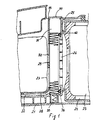
- 21 denotes the housing of a vacuum cleaner, in which housing 21 a dust chamber 22 and a fan chamber containing the blower unit 23 of the vacuum cleaner 24 are formed. Between the dust chamber 22 and the blower chamber 24 there is a partition 25 in which a passage opening 26 for the blower unit 23 intake air is provided. In the dust chamber 22 there is a filter bag 27 receiving filter basket 28 used. Regarding the flow direction of the Suction air is a filter 29 behind the filter basket 28 in between the rear wall 30th of the filter basket 28 and the partition 25 existing space 31 is used.
- the post-filter 29 has a filter element 40 folded in a zigzag shape, the folds of which are arranged horizontally.
- the secondary filter 29 is located on a circumferential one provided on the partition wall 25 Sealing element 32.
- the gap 31 is at the top of the vacuum cleaner housing 21 by means of a Cover part 34 arranged pivotably about an axis 33 is closed.
- a spring element 35 is inserted in the vacuum cleaner housing 21, which is held in its cocked position by a locking cam 36.
- the Locking cam 36 can be arranged on the outside of the vacuum cleaner housing 21 (Not shown in Fig. 1 of the drawing) release element 16 from its Locked position can be released. This releases the tensioned spring element 35 and thereby pushes the post-filter 29 upward out of the intermediate space 31.
- the Cover part 34 is pivoted accordingly.
- the post filter 29 can then Hand pulled out of the space 31.
- the handling of the Postfilter 29 is similar to handling a video or tape cassette, which too easily inserted by hand into a slot provided on the device in question and can be removed from the device by releasing an ejection mechanism can.
- the cover part 34 is folded up, so that the post-filter 29 is inserted into the intermediate space 31 without difficulty can be.
- the spring element 35 is again excited, the locking cam 36 resumes its locking position. At the next The filter can then be ejected again by the spring element 35 after changing the filter become.
- each post-filter 29 can flow one behind the other to be ordered. It is expedient for each post-filter 29 to have its own To assign evaluating spring element 35. When inserting several Post-filter 29 there is the possibility of post-filter 29 with different filter properties to combine, e.g. Charcoal, fragrance, pollen or bacterial filters.
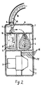
- the blower unit 3 stands with a an air-permeable filter bag 4 receiving dust chamber 5 in suction connection.
- a connecting piece 9 for a suction hose 10 attached.
- the connector 9 forms the entry point 11 for the intake air flow.
- This entry point 11 is located an opening 12 provided in the front wall of the receiving space 6 opposite.
- a removable receptacle e.g. B. a bag 13 or a box. This will handle the vacuum cleaner simplified.
- the filter bag 4 has a number of cassette-like secondary filters 15 downstream in terms of flow, the spatial arrangement of this or this Post-filter 15 in the blower unit 3 upstream of the blower unit 3 is.
- Post-filters 15 with different filter properties can be combined to form a filter combination be compiled so that depending on the type of cleaning operation to be carried out an optimal filter effect is achieved.
- the post-filters 15 each have an ejection mechanism, such as that used in the Embodiment according to Fig. 1 is indicated assigned. This allows the post-filter 15 can be replaced in a simple manner. On the outside of the vacuum cleaner housing 1 release elements 16 are attached, which trigger the ejection mechanism serve the individual post-filter 15.
- Frame or box part are provided, in which several secondary filters 15 can be inserted.
- a filter combination can thus be placed outside the vacuum cleaner housing 1 can be assembled, which then as a unit in the vacuum cleaner housing can be used and removed as a whole from the vacuum cleaner housing can be.
- the vacuum cleaner according to Fig. 2 works as follows: Due to the air flow sucked in by the blower unit 3 (arrows 14), the dirt particles and other parts are taken up by a surface to be cleaned and transported by the air flow through the suction hose 10 to the entrance into the anteroom 7. In the anteroom 7, the air flow is deflected by about 90 °. As a result of their inertia, the heavier parts carried by the air flow cannot fully follow the strong change in direction and essentially maintain their flight direction, which they have when entering the anteroom 7. The heavier parts thus move to the opening 12 of the receiving space 6 opposite the entry point 11 into the antechamber 7 and fly into the receiving space 6, at the bottom of which they collect. The lighter dirt parts, on the other hand, follow the change in direction of the air flow and are transported through it into the filter bag 4, where they are filtered out and collected.
Applications Claiming Priority (2)
| Application Number | Priority Date | Filing Date | Title |
|---|---|---|---|
| DE19909543 | 1999-03-04 | ||
| DE1999109543 DE19909543A1 (de) | 1999-03-04 | 1999-03-04 | Staubsauger |
Publications (1)
| Publication Number | Publication Date |
|---|---|
| EP1033102A2 true EP1033102A2 (fr) | 2000-09-06 |
Family
ID=7899716
Family Applications (1)
| Application Number | Title | Priority Date | Filing Date |
|---|---|---|---|
| EP20000104690 Withdrawn EP1033102A2 (fr) | 1999-03-04 | 2000-03-03 | Aspirateur |
Country Status (2)
| Country | Link |
|---|---|
| EP (1) | EP1033102A2 (fr) |
| DE (1) | DE19909543A1 (fr) |
Cited By (3)
| Publication number | Priority date | Publication date | Assignee | Title |
|---|---|---|---|---|
| WO2004064591A2 (fr) * | 2003-01-24 | 2004-08-05 | Massimiliano Pineschi | Aspirateur ameliore |
| US7181804B2 (en) * | 2002-11-07 | 2007-02-27 | Panasonic Corporation Of North America | Removable dirt cup assembly with external filter |
| US7185394B2 (en) * | 2002-11-07 | 2007-03-06 | Panasonic Corporation Of North America | Dirt cup assembly with attachable and detachable external filter holder |
Family Cites Families (4)
| Publication number | Priority date | Publication date | Assignee | Title |
|---|---|---|---|---|
| US3597903A (en) * | 1968-09-27 | 1971-08-10 | Mil An Mfg Corp | Means for maintaining the suction capacity of a vacuum cleaner |
| DE2454748C3 (de) * | 1974-11-19 | 1978-12-14 | Licentia Patent-Verwaltungs-Gmbh, 6000 Frankfurt | Anordnung eines Nachfilters in einem Staubsauger |
| DE3443837A1 (de) * | 1984-11-30 | 1986-06-05 | Progress-Elektrogeräte Mauz & Pfeiffer GmbH & Co, 7000 Stuttgart | Staubsauger |
| DE8630036U1 (fr) * | 1986-11-10 | 1988-02-25 | Siemens Ag, 1000 Berlin Und 8000 Muenchen, De |
-
1999
- 1999-03-04 DE DE1999109543 patent/DE19909543A1/de not_active Withdrawn
-
2000
- 2000-03-03 EP EP20000104690 patent/EP1033102A2/fr not_active Withdrawn
Cited By (5)
| Publication number | Priority date | Publication date | Assignee | Title |
|---|---|---|---|---|
| US7181804B2 (en) * | 2002-11-07 | 2007-02-27 | Panasonic Corporation Of North America | Removable dirt cup assembly with external filter |
| US7185394B2 (en) * | 2002-11-07 | 2007-03-06 | Panasonic Corporation Of North America | Dirt cup assembly with attachable and detachable external filter holder |
| WO2004064591A2 (fr) * | 2003-01-24 | 2004-08-05 | Massimiliano Pineschi | Aspirateur ameliore |
| WO2004064591A3 (fr) * | 2003-01-24 | 2005-01-06 | Massimiliano Pineschi | Aspirateur ameliore |
| US7608123B2 (en) | 2003-01-24 | 2009-10-27 | Massimiliano Pineschi | Vacuum cleaner |
Also Published As
| Publication number | Publication date |
|---|---|
| DE19909543A1 (de) | 2000-09-07 |
Similar Documents
| Publication | Publication Date | Title |
|---|---|---|
| EP1619987B1 (fr) | Recipient collecteur de poussiere amovible | |
| DE102004050911B4 (de) | Staubsammelvorrichtung für einen Staubsauger | |
| DE3404395C2 (fr) | ||
| DE102004028675B4 (de) | Wirbelungs-Abscheidungsvorrichtung und mit einer solchen Abscheidungsvorrichtung ausgestatteter Staubsauger | |
| DE10331725B3 (de) | Wirbel-Staubfangvorrichtung für einen Staubsauger | |
| EP0211383B1 (fr) | Filtre | |
| DE102012211246A1 (de) | Kombination aus einem Kleinsauger und einem Stielsaugerrahmen sowie Kleinsauger und Stielsaugerrahmen | |
| DE10222656A1 (de) | Zyklon-Staubsammelvorrichtung für die Verwendung in Staubsaugern | |
| DE10303677A1 (de) | Staubsauger | |
| DE10346903A1 (de) | Staubsammelvorrichtung vom Wirbelungstyp für einen Staubsauger | |
| DE10110581A1 (de) | Staubsauger im Hochformat mit einer Staubauffangvorrichtung vom Zyklontyp | |
| DE102008055045A1 (de) | Staubsauger mit Fliehkraftabscheidern | |
| DE102006000310A1 (de) | Staubsaugvorrichtung | |
| DE1404894A1 (de) | Vorrichtung zum Auffangen und Ausscheiden von Faserflug und Staub im Abluftkanal vonBelueftungs- oder Klimaanlagen in Textilbetrieben,insbesondere Spinnereien und Webereien | |
| DE10021594A1 (de) | Staubbox | |
| WO2013013696A1 (fr) | Balayeuse avec conteneur sous pression pour le nettoyage du filtre | |
| DE102004060981B4 (de) | Staubsammelvorrichtung für einen Staubsauger | |
| EP0396803B1 (fr) | Dispositif de filtrage pour un aspirateur de poussières | |
| DE2343971B2 (de) | Gerät zur Fußbodenpflege | |
| EP1033102A2 (fr) | Aspirateur | |
| DE69825486T2 (de) | Staubkollektorelement für luftreiniger | |
| EP2598226B1 (fr) | Dispositif d'épuration | |
| DE102012211248A1 (de) | Kombination aus einem Kleinsauger und einem Stielsaugerrahmen sowie Kleinsauger und Stielsaugerrahmen | |
| DE102006061256B4 (de) | Filteranlage zum Abscheiden von Stäuben aus Gasen | |
| DE202008014127U1 (de) | Filteranordnung für ein Flächenreinigungsfahrzeug und Flächenreinigungsfahrzeug |
Legal Events
| Date | Code | Title | Description |
|---|---|---|---|
| PUAI | Public reference made under article 153(3) epc to a published international application that has entered the european phase |
Free format text: ORIGINAL CODE: 0009012 |
|
| AK | Designated contracting states |
Kind code of ref document: A2 Designated state(s): AT BE CH CY DE DK ES FI FR GB GR IE IT LI LU MC NL PT SE |
|
| AX | Request for extension of the european patent |
Free format text: AL;LT;LV;MK;RO;SI |
|
| STAA | Information on the status of an ep patent application or granted ep patent |
Free format text: STATUS: THE APPLICATION HAS BEEN WITHDRAWN |
|
| 18W | Application withdrawn |
Withdrawal date: 20020425 |