EP1032218B1 - Kodierungs- und dekodierungsvorrichtung und verfahren - Google Patents
Kodierungs- und dekodierungsvorrichtung und verfahren Download PDFInfo
- Publication number
- EP1032218B1 EP1032218B1 EP19990943464 EP99943464A EP1032218B1 EP 1032218 B1 EP1032218 B1 EP 1032218B1 EP 19990943464 EP19990943464 EP 19990943464 EP 99943464 A EP99943464 A EP 99943464A EP 1032218 B1 EP1032218 B1 EP 1032218B1
- Authority
- EP
- European Patent Office
- Prior art keywords
- pixels
- group
- data
- encoding
- level
- Prior art date
- Legal status (The legal status is an assumption and is not a legal conclusion. Google has not performed a legal analysis and makes no representation as to the accuracy of the status listed.)
- Expired - Lifetime
Links
Images


Classifications
-
- H—ELECTRICITY
- H04—ELECTRIC COMMUNICATION TECHNIQUE
- H04N—PICTORIAL COMMUNICATION, e.g. TELEVISION
- H04N11/00—Colour television systems
- H04N11/04—Colour television systems using pulse code modulation
- H04N11/042—Codec means
-
- H—ELECTRICITY
- H04—ELECTRIC COMMUNICATION TECHNIQUE
- H04N—PICTORIAL COMMUNICATION, e.g. TELEVISION
- H04N19/00—Methods or arrangements for coding, decoding, compressing or decompressing digital video signals
- H04N19/10—Methods or arrangements for coding, decoding, compressing or decompressing digital video signals using adaptive coding
- H04N19/134—Methods or arrangements for coding, decoding, compressing or decompressing digital video signals using adaptive coding characterised by the element, parameter or criterion affecting or controlling the adaptive coding
- H04N19/136—Incoming video signal characteristics or properties
- H04N19/14—Coding unit complexity, e.g. amount of activity or edge presence estimation
-
- H—ELECTRICITY
- H04—ELECTRIC COMMUNICATION TECHNIQUE
- H04N—PICTORIAL COMMUNICATION, e.g. TELEVISION
- H04N19/00—Methods or arrangements for coding, decoding, compressing or decompressing digital video signals
- H04N19/10—Methods or arrangements for coding, decoding, compressing or decompressing digital video signals using adaptive coding
- H04N19/102—Methods or arrangements for coding, decoding, compressing or decompressing digital video signals using adaptive coding characterised by the element, parameter or selection affected or controlled by the adaptive coding
- H04N19/103—Selection of coding mode or of prediction mode
- H04N19/105—Selection of the reference unit for prediction within a chosen coding or prediction mode, e.g. adaptive choice of position and number of pixels used for prediction
-
- H—ELECTRICITY
- H04—ELECTRIC COMMUNICATION TECHNIQUE
- H04N—PICTORIAL COMMUNICATION, e.g. TELEVISION
- H04N19/00—Methods or arrangements for coding, decoding, compressing or decompressing digital video signals
- H04N19/10—Methods or arrangements for coding, decoding, compressing or decompressing digital video signals using adaptive coding
- H04N19/169—Methods or arrangements for coding, decoding, compressing or decompressing digital video signals using adaptive coding characterised by the coding unit, i.e. the structural portion or semantic portion of the video signal being the object or the subject of the adaptive coding
- H04N19/182—Methods or arrangements for coding, decoding, compressing or decompressing digital video signals using adaptive coding characterised by the coding unit, i.e. the structural portion or semantic portion of the video signal being the object or the subject of the adaptive coding the unit being a pixel
-
- H—ELECTRICITY
- H04—ELECTRIC COMMUNICATION TECHNIQUE
- H04N—PICTORIAL COMMUNICATION, e.g. TELEVISION
- H04N19/00—Methods or arrangements for coding, decoding, compressing or decompressing digital video signals
- H04N19/50—Methods or arrangements for coding, decoding, compressing or decompressing digital video signals using predictive coding
- H04N19/593—Methods or arrangements for coding, decoding, compressing or decompressing digital video signals using predictive coding involving spatial prediction techniques
Definitions
- the present invention relates to an apparatus and method for encoding images, and also to a decoding apparatus and method for decoding coded data.
- television signals have been encoded by using data about the surrounding of the pixels to be transmitted. This is because an image generally exhibits acute auto correlation with a neighboring region. Thus, the data about the neighboring region should be used to compress data efficiently.
- any correlation cannot be said to exist at an edge part of an image, where the signal greatly change, whereas the correlation is strong at a flat part where the signal does not change.
- That part where the correlation is strong is encoded by fully using the strong correlation, while the edge part is encoded by applying a suitable amount of data or is encoded within a scope where visual masking effect can be obtained.
- An object of the invention is to provide an encoding apparatus and method which can reduce an amount of data even at an edge part and which can encode signal values with high efficiency.
- Another object of the present invention is to provide a decoding apparatus and method which can easily decode an image encoded in accordance with its characteristics and then transmitted.
- a decoding apparatus according to the invention is provided in claim 10 appended hereto.
- a decoding method according to the invention is provided in claim 24 appended hereto.
- the embodiment is such an image-processing system 1 as is shown in FIG. 1 .
- the system 1 comprises an encoding apparatus 2, a transmission medium 10, and a decoding apparatus 6.
- the encoding apparatus 2 encodes digital pixel data and outputs coded image data.
- the transmission medium 10 transmits the coded image data output by the encoding apparatus 2.
- the decoding apparatus 6 receives and decodes the coded image data transmitted by the transmission medium 10.
- the encoding apparatus 2 divides image signals provided in units of frames, each having a plurality of pixel data items, or pixels, into macro groups.
- the pixel data items which exist in each macro group and which are correlated are combined, forming a group.
- the encoding apparatus 2 encodes the pixel data items of the group, in accordance with the signal-level data representing the level of the representative pixel data item in the group, the address data of all pixel data items of the group, and pixel-number data representing the number of pixels existing in the group.
- the grouping of the pixel data item may be performed either in units of frames or in units of fields.
- the decoding apparatus 6 decodes the coded pixel data items in the macro block transmitted from the encoding apparatus 2 through the transmission medium 10, in the order the pixel data items are arranged in the macro block. To decode the pixel data items, the decoding apparatus uses the signal-level data extracted from the coded pixel data items, the above-mentioned address data and the aforementioned pixel-number data.
- the image signals provided in units of frames, each having a plurality of pixel data items are divided into macro groups, and the pixel data items in each macro group are combined, forming a group, and then encoded.
- digital pixel data items are input to an input terminal INt in the order they have been raster-scanned.
- the pixel data items are accumulated in memories 3a and 3b.
- the memories 3a and 3b are of bank-switching structure. That is, the pixel data items of a macro block are written into one of the memories 3a and 3b, while the pixel data items of another macro block are being read from the other of the memories 3a and 3b. Therefore, a macro block reading section 4 can read the pixel data items of one macro block at a time and the pixel data items of another macro block at a different time.
- the image data that the macro block reading section 4 has read in units of macro blocks is supplied to an encoder 5.
- the encoder 5 evaluates the correlation among the pixel data items in each macro block, forming groups of pixel data items, reduces redundancy in each of the groups, and outputs coded pixel data.
- FIG. 2 shows the structure of the encoder 5.
- the encoder 5 comprises a memory 11, an evaluating section 13, a differential coding section 16, and a multiplexing section 17.
- the memory 11 temporarily stores the pixel data the macro block reading section 4 shown in FIG. 1 has read in units of macro blocks.
- the evaluating section 13 evaluates the correlation of the signal-level data of the pixel data item representing a group to be formed of the pixel data items stored in the memory 11 in units of macro blocks, with respect to the signal-level data of the other pixel data items.
- the section 13 also evaluates the correlation between the address data of the pixel data item representing the group and the address data of the other pixel data items.
- the differential coding section 16 encodes the pixel data items of each group formed by evaluating the correlation by the evaluating section 13 in accordance with three types of data.
- the first type is the signal-level data of the pixel data item representing the group.
- the second type is the address data of all pixel data items of the group.
- the third type is the pixel-number data representing the number of all pixel data items of the group.
- the multiplexing section 17 multiplexes the differential coded data output from the differential coding section 16.
- the encoder 5 has an address counter 12, which counts address data items of all pixel data items of the group.
- the encoder 5 first selects a representative pixel data item in Step S1. To select the representative pixel data item, an optimal method may be used that is based on a prescribed algorithm.
- the encoder 5 finds the difference between the signal-level data of the representative pixel data item selected in Step S1 and the signal-level data of the representative pixel data items of the other groups in the same macro block, by using a register14 R , a register14 G , a register14 B , a subtracter15 R , a substracter 15 G and a substracter 15 B .
- the difference obtained is supplied to the differential coding section 16 (Step S2). Like Step S6 that will be described later, this process precedes the differential coding that the differential coding section 16 effects in the encoder 5.
- the signal-level data of the representative pixel data item is RGB-tricolor signal-level data.
- the signal-level data of the pixel data items are also RGB-tricolor signal-level data. Instead, the signal-level data may of course be luminance signal Y, blue difference signal Cb and red difference signal Cr.
- Step S3 the evaluating section 13 of the encoder 5 evaluates the correlation between the representative pixel data item selected in Step S1 and a given pixel data item in the same macro block (Step S3).
- Step S4 it is determined whether the given pixel data item should be considered as belonging to the same group.
- the correlation between the RGB-tricolor signal-level data (R 0 , G 0 , B 0 ) of the representative pixel data item and the signal-level data (R i , G i , B i ) of a given pixel data item in the same macro block is evaluated by using the following equations (1), thereby determining whether the given pixel data item is of the same group or not.
- R 0 - R i ⁇ n
- G 0 - G i ⁇ n
- B 0 - B i ⁇ n
- the evaluating section 13 has a group-determining unit 22, which is shown in FIG. 4 .
- the group-determining unit 22 comprises correlation determining units 25 R , 25 G and 25 B , a NAND gate 26, and registers 27 R , 27 G and 27 B .
- the correlation determining units 25 R , 25 G and 25 B receive the signal-level data of the representative pixel data item and the signal-level data of the given pixel data item.
- the NAND gate 26 receives the outputs of the correlation determining units 25 R , 25 G and 25 B .
- the registers 27 R , 27 G and 27 B receive the control signal supplied from the NAND gate 26. The control signal will be described later.
- the correlation determining units 25 R , 25 G and 25 B determine the correlation values
- the correlation values the units 25 R , 25 G and 25 B have determined may be equal to or less than the threshold value (strain n). In other words, the representative pixel data item and the given pixel data item have high correlation. If so, the NAND gate 26 supplies the control signal to the registers 27 R , 27 G and 27 B , which will be described later.
- the registers 27 R , 27 G and 27 B receive the signal-level data (R 1 , G i , B i ) of the given pixel data item supplied via the correlation determining units 25 R , 25 G and 25 B .
- the registers 27 R , 27 G and 27 B then outputs the signal-level data (R i , G i , B i ) in response to the control signal supplied from the NAND gate 26.
- the signal-level data will be used as pixel data that satisfies the above equation (1)
- the group determining unit 22 has registers 27 X and 27 Y , which output the address data X and Y of the given pixel data item that satisfies the equation (1).
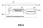
- Each of the correlation determining units 25 (e.g., unit 25 R ) comprises a subtracter 31, an absolute value generator 32 and a comparator 33, as is illustrated in FIG. 5 .
- the subtracter 31 subtracts the level data R i (post-value) of the given pixel data item from the signal-level data R 0 (pre-value).
- the absolute value generator 32 generates the absolute value of the result of the subtraction.
- the comparator 33 compares the absolute value with the threshold value n.
- the difference C R between the absolute value and the threshold value n is output to the NAND gate 26 shown in FIG. 4 .
- the level data R i (post-value) of the given pixel data item is supplied to the register 27 R .
- Step S4 If it is determined in Step S4 that the given pixel data item does not belong to the same group as the representative pixel data item, the flow returns to Step S3. Then, Steps S3 and S4 are repeated on another given pixel data item.
- the evaluating section 13 counts the given pixel data items that have been regarded in Step S4 as belong to the same group (Step S5).
- the count thus obtained is the data showing the number of pixels existing in the same group.
- the differential coding section 16 performs encoding.
- the register 14 X and 14 Y and the substracters 15 X and 15 Y are used in Step S6, the difference between the given pixel data items is obtained and supplied to the differential coding section 16.
- the address data of the representative pixel data item is also generated, by means of subtraction, from the address data of the representative pixel data item of another group that has been encoded in the same macro block.
- Step S8 the encoder 5 determines whether the given pixel data items have been found in the macro block, that is, whether the entire macro block has been searched. If the given pixel data items have not been found, Steps S3 to S6 are repeated. If the given pixel data items have been found, the flows goes to Step S8, in which the pixel data items belonging to the group are supplies via a register 19 to a pixel-number data encoder 19.
- the encoder 5 repeats Steps S1 to S8 until it is detennined that all pixel data items in the macro group have been supplied to a pixel-number data encoder 19. That is, in the encoder 5, the groups of pixel data items, which belong to the macro block, are processed, and the difference data items and pixel data items are supplied to the encoders.
- the encoder 5 uses the differential encoders 16 R , 16 G , 16 B , 16 X and 16 Y of the differential coding section 16, thereby encoding the signal levels R, G and B of the representative pixel data item and the address data of each pixel data item in the group.
- each signal level is the difference between one representative pixel data item and that of the immediately preceding group.
- the address data of the pixel data item is obtained from the difference between the address data of one pixel data item and the address data of the representative pixel data item, which in turn is the difference between the address data of the representative pixel data item and that of the representative pixel data item of the immediately preceding group.
- the differential encoders 16 R , 16 G and 16 B encode the signal-level data (R i , G i , B i ) of the representative pixel data item Pi of a group G(i), that is to be transmitted.
- the differential encoders 16 R , 16 G and 16 B also encode the differential value of the signal-level data (R 1-1 , G i-1 , B i-1 ) of the representative pixel data item P i-1 in the other group G (i-1) that has been encoded immediately before the group G(i).
- the differential encoders 16 X and 16 Y encode the address data items (X 1 , Y 1 ), (X n , Y n ) of the pixel data items, with respect to the address data (X 0 , Y 0 ) of the representative pixel data item Pi of the same group, which has been obtained as a difference from the address data of the representative pixel data item P i-1 of the preceding group.
- the encoder 5 utilizes the pixel-number data encoder 19, thereby encoding the pixel data items within the group.
- the differential encoding effected in the encoder 5 may be DPCM (Differential Pulse Code Modulation) or an encoding method in which the frequency of differential values is optimized and then encoded by using Huffman codes.
- the multiplexing section 17 multiplexes the differential coded data output from the differential coding section 16 and the coded data output from the pixel-number data encoder.
- the coded pixel data thus multiplexed, is supplied from the output terminal OUT T of the encoder 5 to the transmission medium 10.
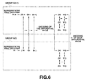
- FIG. 7 shows the format of the coded pixel data.
- One coded pixel data is composed of a pixel data item S35, the signal-level data (R, G, B) 36 of the representative pixel data item, and address data (X, Y) 37 of the group.
- the transmission medium 10 may be a communication path such as a network, a disk-shaped recording medium, or a tape-shaped recording medium.
- the coded pixel data transmitted through the transmission medium 10 is input to the decoding apparatus 6 via an input terminal IN R .
- the decoding apparatus 6 will now be described in detail, with reference to FIG. 1 .
- the coded pixel data input to the input terminal IN R is supplied to a decoder 7.
- the decoder 7 decodes the signal-level data of the representative pixel data item and extracts the same from the coded pixel data of each group.
- the decoder 7 also decodes a plurality of address data items and extracts them from the coded pixel data of each group.
- the decoded value of the signal-level data is stored in bank-switched memories 9a and 9b, at storage locations based on the address data (X, Y).
- a macro block reading section 8 reads the level data items in the macro block from the memories 9a and 9b, one after another in the order they are raster-scanned.
- the level data items, thus read, are supplied from an output terminal OUT R .
- the decoder 7 effects the decoding method according to the present invention.
- the decoding method is designed to form a group of image signals in a macro block, which are pixel data items arranged in a specific order, and to decode the coded pixel data items to a plurality of image data items arranged in a particular order.
- the pixel data items of each group are read out in the order they are raster-scanned, in accordance with the signal-level data of the representative pixel data item, address data items of the coded pixel data items and data showing the number of the coded pixel data items, all having been extracted for the group.
- the decoder 7 comprises a data dividing section 42, a differential decoding section 43, adders 44, registers 45, and macro block memories 46a and 46b.
- the dividing section 42 divides the coded pixel data generated by the encoder 5 by means of multiplexing and having the format shown in FIG. 7 , into signal-level data (R, G, B) 36 of the representative pixel data item, address data (X, Y) 37 of all pixel data items of the group, and data showing the number of pixel data items in the group.
- the differential decoding section 43 decodes differential data from the code values relating to the signal-level data and the address data, both generated by the data dividing section 42.
- the adders 44 and the registers 45 constitute a decoding section that generates the signal-level data and address data of each pixel data item from the decoded differential output of the differential decoding section 43.
- the pixel data items are read from the macro block memories 46a and 46b, in the order they are raster-scanned, after the signal-level data (R, G, B) has been written into the memories 46a and 46b in accordance with the address data (X, Y).
- the addresses for reading data from the macro block memories 46a and 46b are counted by an address counter 47, as addresses that accord with the order in which the pixel data items are raster-scanned.
- the decoder 7 further comprises a pixel-number data decoding section 49 and a register 50.
- the section 49 decodes the pixel-number data S35 which represents the number of pixel data items in the group and which has been generated by the data dividing section 42.
- the register 50 stores the pixel-number data decoded by the pixel-number data decoding section 49.
- the dividing section 42 divides the coded pixel data input via the input terminal IN R and having the format shown in FIG. 7 , into differential coded value of the signal-level data, differential coded value of the address data, and coded value of the pixel-number data. These values are supplied to the differential decoders 43 R , 43 G , 43 B , 43 X and 43 Y and the differential decoding section 43 and to the pixel-number data decoding section 49. More specifically, the coded pixel data can be divided into these values by determining the number of address data items from the pixel-number data recorded in a header.
- the differential values of the signal-level data, decoded by the differential decoders 43 R , 43 G , 43 B , 43 X and 43 Y and the differential value of the address data are supplied to the adders 44 R , 44 G , 44 B , 44 X and 44 Y that constitute the above-mentioned decoding section.
- the signal-level data of the present representative pixel data item can therefore be decoded.
- the pixel-number data stored in the register 50 is supplied to the 45 X and 45 Y and used to extract the address data.
- Each output of the decoding section is supplied to the macro block memories 46a and 46b that have a bank-switching structure.
- the address counter 47 reads the address data that has been used in the decoding, as described above, by means of raster scanning.
- the image signal that has been raster-scanned is output from the macro block memories 46a and 46b and output through an output terminal 48.
- a one-frame image signal having a plurality of pixel data items is divided into a plurality of macro blocks.
- the pixel image items correlated to one another in each macro block form one group.
- the pixel data items in each group are encoded on the basis of the signal-level data representing the signal level of the representative pixel data item of the group, the address data of all pixel data items of the group and the pixel-number data showing the number of the pixel data items existing in the group.
- the amount of data can be reduced.
- the operating speed of the encoder increases because groups of pixel data items are formed, each having a representative pixel data item.
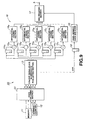
- the encoder 5 may be replaced by the encoder 50 illustrated in FIG. 9 .
- the encoder 50 is different from the encoder 5 in that a data deleting section 51 connected to the input of the evaluating section 13.
- the data deleting section 51 deletes the signal-level data and address data from the pixel data.
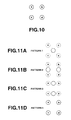
- the principle of the data deleting section 51 will be related, with reference to FIGS. 10 and 11 .
- the signal distribution of four pixels constituting a 2 x 2 block is converted to the four-pattern pixel density that is schematically shown in FIG. 11 .
- the four pixels have pixel values a, b, c and d, respectively.
- the pattern 1 shown in FIG. 11A is replaced by (a + b + c + d)/4 when all conditions of
- the pattern 2 shown in FIG. 11B is replaced by (a + c)/2 and (b +d)/2 when only the conditions of
- 11C is replaced by (a + b )/2 and (c + d)/2 when only the conditions of
- the pattern 4 shown in FIG. 11D has the original pixel value when none of these conditions is satisfied.
- the use of the encoder 50 having the data deleting section 51 can further reduce the amount of data.
- FIG. 12 shows a decoder 53 that should be used in combination with the encoder 50.
- a pixel-address interpolating section 55 must perform interpolation on the image signals read from the macro block memories 46a and 46b, by using a line memory 54.
- the output of the section 55 i.e., the image signals interpolated, is supplied from an output terminal 56.
- image signals each consisting of a plurality of pixel data items, or pixels, are divided into groups, thereby encoding image data.
- the image data, thus encoded, is transmitted. It is therefore possible to enhance the efficiency of encoding the values of the image signals. Since address data that is unnecessary for raster scanning is transmitted, the amount of data increases proportionally. Nevertheless, the data representing the signal values can be reduced more than the amount of data increases. As a result, the efficiency of encoding the signal values increases.
- the pixel data items, divided into groups and encoded, can be decoded by the use of a decoding apparatus that is simple in structure.
Landscapes
- Engineering & Computer Science (AREA)
- Multimedia (AREA)
- Signal Processing (AREA)
- Compression Or Coding Systems Of Tv Signals (AREA)
- Compression, Expansion, Code Conversion, And Decoders (AREA)
- Compression Of Band Width Or Redundancy In Fax (AREA)
Claims (28)
- Codiervorrichtung (2), welche umfasst:einen Datengruppierabschnitt (4) zum Unterteilen mehrerer Pixel eines Bildsignals in Gruppen gemäß Kenndaten des Bildsignals; undeinen Codierabschnitt (16) zum Codieren der Pixel jeder der Gruppen auf Basis von Pegeldaten, welche einen Signalpegel eines repräsentativen Pixels der Gruppe zeigen, und Adressdaten, welche Adressen der Pixel der Gruppe zeigen, wobei das repräsentative Pixel unter allen Pixeln der Gruppe ausgewählt wird und der Datengruppierabschnitt die Pixel in Gruppen unter Verwendung, als Kenndaten, von Korrelation zwischen dem repräsentativen Pixel und den anderen Pixeln des Bildsignals unterteilt.
- Codiervorrichtung nach Anspruch 1, wobei der Datengruppierabschnitt die Pixel in Gruppen unter Verwendung, als Kenndaten, von Korrelation zwischen den Pegeldaten des repräsentativen Pixels und den Pegeldaten der anderen Pixel und der Korrelation zwischen den Adressdaten des repräsentativen Pixels und den Adressdaten der anderen Pixel unterteilt.
- Codiervorrichtung nach Anspruch 1, wobei der Datengruppierabschnitt (41) die Pixel, welche in einem vorgeschriebenen Bereich enthalten sind, in Gruppen unterteilt.
- Codiervorrichtung nach Anspruch 3, wobei die Adressdaten eine Adresse im vorgeschriebenen Bereich zeigen.
- Codiervorrichtung nach Anspruch 3, wobei der vorgeschriebene Bereich ein Rahmen oder ein Feld ist.
- Codiervorrichtung nach Anspruch 5, wobei der vorgeschriebene Bereich ein Makroblock im Rahmen oder im Feld ist.
- Codiervorrichtung nach Anspruch 1, wobei der Codierabschnitt die Pegeldaten des repräsentativen Pixels einer bestimmten Gruppe auf Basis einer Differenz zwischen den Pegeldaten des repräsentativen Pixels und den Pegeldaten des repräsentativen Pixels einer Gruppe, die unmittelbar vorher codiert wurde, codiert.
- Codiervorrichtung nach Anspruch 7, wobei der Codierabschnitt die Adressdaten der Pixel der Gruppe auf Basis der Differenzwerte der Adressdaten entsprechend codiert.
- Codiervorrichtung nach Anspruch 1, wobei der Codierabschnitt die Pixel in der Gruppe auf Basis der Pegeldaten der repräsentativen Pixeldaten, der Adressdaten aller Pixel der Gruppe und der Pixelzahldaten, welche die Zahl von Pixeln zeigen, welche in der Gruppe existieren, codiert.
- Decodiervorrichtung (6) zum Decodieren mehrerer Pixel, welche eine vorher bestimmte Reihenfolge haben, von mehreren codierten Pixeln, welche erzeugt wurden, indem ein Bildsignal, welches aus Pixeln zusammengesetzt ist, welche die vorher bestimmte Reihenfolge haben, in mehrere Gruppen gemäß Kenndaten des Bildsignals unterteilt werden und indem die Pixel jeder Gruppe auf Basis der Pegeldaten, welche einen Signalpegel eines repräsentativen Pixels der Gruppe zeigen, und der Adressdaten, welche Adressen der Pixel der Gruppe zeigen, codiert werden, wobei das repräsentative Pixel unter allen Pixeln der Gruppe ausgewählt wird, wobei die Decodiervorrichtung (6) umfasst:einen Pegeldaten-Extraktionsabschnitt (44, 45) zum Extrahieren der Pegeldaten von den codierten Pixeln jeder Gruppe;einen Adressdaten-Extraktionsabschnitt (47) zum Extrahieren mehrerer Adressdatenposten von den codierten Pixeln jeder Gruppe; undeinen Datenumsetzungsabschnitt (49) zum Umsetzen der Pixel jeder Gruppe in die vorher festgelegte Reihenfolge auf Basis der Pegeldaten, welche durch den Pegeldaten-Extraktionsabschnitt extrahiert wurden, und der mehreren Adressdaten, welche durch den Adressdaten-Extraktionsabschnitt extrahiert wurden, wobei die mehreren codierten Pixel durch Codieren der Pixel jeder Gruppe erzeugt wurden, indem Pixelzahldaten, welche die Zahl von Pixeln darstellen, welche in der Gruppe existieren, verwendet werden.
- Decodiervorrichtung nach Anspruch 10, welche außerdem einen Pixelzahl-Datenextraktionsabschnitt umfasst, um von den codierten Pixeln die Daten, welche die Zahl von Pixeln darstellen, welche in jeder Gruppe existieren, zu extrahieren, und wobei der Datenumsetzungsabschnitt die Pixel jeder Gruppe in die vorher bestimmte Reihenfolge auf Basis der Pixelzahldaten, der Pegeldaten und der mehreren Adressdaten umsetzt.
- Decodiervorrichtung nach Anspruch 10, wobei die mehreren Pixel jedes vorgeschriebenen Bereichs in Gruppen unterteilt sind.
- Decodiervorrichtung nach Anspruch 10, wobei der vorgeschriebene Bereich ein Rahmen oder ein Feld ist.
- Decodiervorrichtung nach Anspruch 10, wobei der vorgeschriebene Bereich ein Makroblock in einem Rahmen oder einem Feld ist.
- Codierverfahren, welches umfasst:einen Schritt zum Unterteilen mehrerer Pixel eines Bildsignals in Gruppen gemäß Kenndaten des Bildsignals; undeinen Schritt zum Codieren der Pixel jeder Gruppe auf Basis von Pegeldaten, welche einen Signalpegel eines repräsentativen Pixels der Gruppe zeigen, und Adressdaten, welche Adressen der Pixel der Gruppe zeigen, wobei das repräsentative Pixel unter allen Pixeln der Gruppe ausgewählt wird und die Pixel in Gruppen unter Verwendung, als Kenndaten, von Korrelation zwischen dem repräsentativen Pixel und den anderen Pixeln des Bildsignals unterteilt werden.
- Codierverfahren nach Anspruch 15, wobei die Pixel in Gruppen unter Verwendung, als Kenndaten, von Korrelation zwischen den Pegeldaten des repräsentativen Pixels und den Pegeldaten der anderen Pixel und der Korrelation zwischen den Adressdaten des repräsentativen Pixels und den Positionsdaten der anderen Pixel unterteilt werden.
- Codierverfahren nach Anspruch 16, wobei die Pixel, welche in Gruppen unterteilt sind, in einem vorgeschriebenen Bereich enthalten sind.
- Codierverfahren nach Anspruch 17, wobei die Adressdaten eine Adresse im vorgeschriebenen Bereich zeigen.
- Codierverfahren nach Anspruch 17, wobei der vorgeschriebene Bereich ein Rahmen oder ein Feld ist.
- Codierverfahren nach Anspruch 19, wobei der vorgeschriebene Bereich ein Makroblock in einem Rahmen oder einem Feld ist.
- Codierverfahren nach Anspruch 15, wobei im Codierschritt die Pegeldaten des repräsentativen Pixels einer bestimmten Gruppe auf Basis einer Differenz zwischen den Pegeldaten des entsprechenden Pixels und den Pegeldaten des entsprechenden Pixels einer Gruppe, welche unmittelbar vorher codiert wurde, codiert werden.
- Codierverfahren nach Anspruch 21, wobei im Codierschritt die Adressdaten der Pixel der Gruppe auf Basis von Differenzwerten der Adressdaten entsprechend codiert werden.
- Codierverfahren nach Anspruch 15, wobei im Codierschritt die Pixel in der Gruppe auf Basis der Pegeldaten des repräsentativen Pixels, der Adressdaten aller Pixel der Gruppe und der Pixelzahldaten, welche die Zahl von Pixeln zeigen, welche in der Gruppe existieren, codiert werden.
- Decodierverfahren zum Decodieren mehrerer Pixeln, welche eine vorher festgelegte Reihenfolge haben, von mehreren codierten Pixeln, welche erzeugt wurden, indem ein Bildsignal, welches aus Pixeln zusammengesetzt ist, welche die vorher festgelegte Reihenfolge haben, in mehrere Gruppen gemäß Kenndaten des Bildsignals unterteilt wird, und indem die Pixel jeder Gruppe auf Basis der Pegeldaten, welche einen Signalpegel des repräsentativen Pixels der Gruppe zeigen, und Adressdaten, welche Adressen der Pixel der Gruppe zeigen, codiert werden, wobei das repräsentative Pixel unter allen Pixeln der Gruppe ausgewählt wird, wobei das Decodierverfahren umfasst:einen Schritt zum Extrahieren der Pegeldaten von den codierten Pixeln jeder Gruppe;einen Schritt zum Extrahieren mehrerer Adressdaten von den codierten Pixeln jeder Gruppe; undeinen Schritt zum Umsetzen der Pixel jeder Gruppe in die vorher festgelegte Reihenfolge auf Basis der Pegeldaten, die extrahiert wurden, und der mehreren Adressdaten, die extrahiert wurden, wobei die mehreren codierten Pixel durch Codieren der Pixel jeder Gruppe erzeugt wurden, indem Pixelzahldaten, welche die Zahl von Pixeln zeigen, welche in der Gruppe existieren, verwendet werden.
- Decodierverfahren nach Anspruch 24, welches außerdem einen Pixelzahl-Datenextraktionsschritt aufweist, um von den codierten Pixeln die Daten zu extrahieren, welche die Zahl von Pixeln zeigen, welche in jeder Gruppe existieren, und wobei im Umsetzungsschritt die Pixel jeder Gruppe in die vorher bestimmte Reihenfolge auf Basis der Pixelzahldaten, der Pegeldaten und der mehreren Adressdaten umgesetzt werden.
- Decodierverfahren nach Anspruch 24, wobei die mehreren Pixel jedes vorgeschriebenen Bildbereichs in Gruppen unterteilt werden.
- Decodierverfahren nach Anspruch 26, wobei der vorgeschriebene Bereich ein Rahmen oder ein Feld ist.
- Decodierverfahren nach Anspruch 27, wobei der vorgeschriebene Bereich ein Makroblock in einem Rahmen oder einem Feld ist.
Applications Claiming Priority (3)
| Application Number | Priority Date | Filing Date | Title |
|---|---|---|---|
| JP26698598 | 1998-09-21 | ||
| JP26698598 | 1998-09-21 | ||
| PCT/JP1999/005167 WO2000018126A1 (en) | 1998-09-21 | 1999-09-21 | Coding device and method, and decoding device and method |
Publications (3)
| Publication Number | Publication Date |
|---|---|
| EP1032218A1 EP1032218A1 (de) | 2000-08-30 |
| EP1032218A4 EP1032218A4 (de) | 2005-06-15 |
| EP1032218B1 true EP1032218B1 (de) | 2010-03-03 |
Family
ID=17438466
Family Applications (1)
| Application Number | Title | Priority Date | Filing Date |
|---|---|---|---|
| EP19990943464 Expired - Lifetime EP1032218B1 (de) | 1998-09-21 | 1999-09-21 | Kodierungs- und dekodierungsvorrichtung und verfahren |
Country Status (6)
| Country | Link |
|---|---|
| US (1) | US6463179B1 (de) |
| EP (1) | EP1032218B1 (de) |
| JP (1) | JP4846903B2 (de) |
| KR (1) | KR100656690B1 (de) |
| DE (1) | DE69942086D1 (de) |
| WO (1) | WO2000018126A1 (de) |
Families Citing this family (6)
| Publication number | Priority date | Publication date | Assignee | Title |
|---|---|---|---|---|
| WO2000018133A1 (en) * | 1998-09-21 | 2000-03-30 | Sony Corporation | Encoding device and method, and decoding device and method |
| EP1753242A2 (de) * | 2005-07-18 | 2007-02-14 | Matsushita Electric Industrial Co., Ltd. | Schaltbare Modus- und Prädiktions-Informationskodierung |
| JP2008227702A (ja) * | 2007-03-09 | 2008-09-25 | Oki Electric Ind Co Ltd | 動きベクトル探索装置、動きベクトル探索方法及び動きベクトル探索プログラム |
| JP2009225260A (ja) * | 2008-03-18 | 2009-10-01 | Fujitsu Ten Ltd | 制御装置、制御方法、車両の制御装置、及び車両の制御システム |
| US7701366B2 (en) * | 2008-07-25 | 2010-04-20 | Seiko Epson Corporation | Data compression by multi-order differencing |
| JP2015050671A (ja) * | 2013-09-02 | 2015-03-16 | 株式会社東芝 | 固体撮像装置 |
Family Cites Families (14)
| Publication number | Priority date | Publication date | Assignee | Title |
|---|---|---|---|---|
| JPS62100077A (ja) * | 1985-10-28 | 1987-05-09 | Nippon Telegr & Teleph Corp <Ntt> | 符号化方法および装置 |
| US5225904A (en) * | 1987-10-05 | 1993-07-06 | Intel Corporation | Adaptive digital video compression system |
| US4953019A (en) * | 1987-11-27 | 1990-08-28 | Canon Kabushiki Kaisha | Image signal encoding apparatus |
| US5220440A (en) * | 1990-10-10 | 1993-06-15 | Fuji Xerox Co., Ltd. | Data compression method having a fixed ratio of compression for image data, and image data compression device |
| JP2621747B2 (ja) * | 1992-10-06 | 1997-06-18 | 富士ゼロックス株式会社 | 画像処理装置 |
| JPH07123269A (ja) * | 1993-10-22 | 1995-05-12 | Fuji Xerox Co Ltd | 画像信号の符号化装置 |
| JPH07212760A (ja) * | 1994-01-14 | 1995-08-11 | Nippon Telegr & Teleph Corp <Ntt> | 動画像の動き補償予測符号化方法 |
| US5552832A (en) * | 1994-10-26 | 1996-09-03 | Intel Corporation | Run-length encoding sequence for video signals |
| US5978514A (en) * | 1994-11-10 | 1999-11-02 | Kabushiki Kaisha Toshiba | Image data coding and decoding system for efficiently compressing information using the shape and position of the image content |
| JPH09219856A (ja) * | 1996-02-13 | 1997-08-19 | Sharp Corp | 画像符号化装置 |
| US5740278A (en) * | 1996-02-16 | 1998-04-14 | Cornell Research Foundation, Inc. | Facsimile-based video compression method and system |
| JP4049280B2 (ja) * | 1996-09-24 | 2008-02-20 | 株式会社ハイニックスセミコンダクター | グレースケール形状情報符号化/復号化装置及び方法 |
| JP3796844B2 (ja) * | 1996-10-04 | 2006-07-12 | ソニー株式会社 | 画像処理装置、画像処理方法、パラメータ生成装置およびパラメータ生成方法 |
| US5982938A (en) * | 1997-03-31 | 1999-11-09 | Iterated Systems, Inc. | System and method for compressing data using differential coding of coefficient addresses |
-
1999
- 1999-09-21 JP JP2000571662A patent/JP4846903B2/ja not_active Expired - Fee Related
- 1999-09-21 KR KR1020007005438A patent/KR100656690B1/ko not_active IP Right Cessation
- 1999-09-21 WO PCT/JP1999/005167 patent/WO2000018126A1/ja active IP Right Grant
- 1999-09-21 DE DE69942086T patent/DE69942086D1/de not_active Expired - Lifetime
- 1999-09-21 EP EP19990943464 patent/EP1032218B1/de not_active Expired - Lifetime
-
2000
- 2000-05-18 US US09/574,136 patent/US6463179B1/en not_active Expired - Fee Related
Also Published As
| Publication number | Publication date |
|---|---|
| EP1032218A4 (de) | 2005-06-15 |
| KR100656690B1 (ko) | 2006-12-19 |
| WO2000018126A1 (en) | 2000-03-30 |
| EP1032218A1 (de) | 2000-08-30 |
| US20020075955A1 (en) | 2002-06-20 |
| US6463179B1 (en) | 2002-10-08 |
| KR20010032237A (ko) | 2001-04-16 |
| DE69942086D1 (de) | 2010-04-15 |
| JP4846903B2 (ja) | 2011-12-28 |
Similar Documents
| Publication | Publication Date | Title |
|---|---|---|
| EP1473943B1 (de) | Verfahren zur Bildkodierung, Verfahren zur Bildkodierung/-Dekodierung, Bildkodierer, oder Vorrichtung zur Bildaufzeichnung/-Wiedergabe | |
| US5566002A (en) | Image coding/decoding method and apparatus | |
| CN101969566B (zh) | 运动图像编码装置以及运动图像编码方法 | |
| EP1512115B1 (de) | Intracodierung auf der basis räumlicher prädiktion | |
| EP2257070B1 (de) | Bildkodierer | |
| EP0750426B1 (de) | Bildverarbeitungsgerät, Datenverarbeitungsgerät und Verfahren | |
| US8238437B2 (en) | Image encoding apparatus, image decoding apparatus, and control method therefor | |
| EP0899959A2 (de) | Verfahren und Vorrichtung zur Kodierung und Wiederherstellung von Bilddaten | |
| JP2997355B2 (ja) | 復号装置 | |
| EP0776569B1 (de) | Verfahren und system zur kodierung und dekodierung von bilddaten | |
| US20070064275A1 (en) | Apparatus and method for compressing images | |
| EP0932306A2 (de) | Verfahren und Vorrichtung zur Kodierung von Videokontur- und Texturinformation | |
| EP1032218B1 (de) | Kodierungs- und dekodierungsvorrichtung und verfahren | |
| JP3231800B2 (ja) | 画像符号化装置及び画像符号化方法 | |
| US20010012405A1 (en) | Image coding method, image decoding method, image coding apparatus, image decoding apparatus using the same methods, and recording medium for recording the same methods | |
| EP1033885B1 (de) | Kodier- und dekodierverfahren sowie vorrichtung | |
| EP0776133A2 (de) | Bildsignaldekodierer | |
| EP1575263A1 (de) | Bildkodierungseinrichtung und -verfahren und dekodierungseinrichtung und -verfahren für kodierte bilder | |
| JPH09326024A (ja) | 画像符号及び復号化方法とその装置 | |
| KR20010110053A (ko) | 동화상 정보의 압축 방법 및 그 시스템 | |
| US20020044684A1 (en) | Data processor and method of data processing | |
| JPH06113291A (ja) | 画像符号化及び復号化装置 | |
| JP2002209111A (ja) | 画像符号化装置、画像通信システムおよびプログラム記録媒体 | |
| JP2005236723A (ja) | 動画像符号化装置、動画像符号化方法、動画像復号化装置及び動画像復号化方法 | |
| JPH07111595A (ja) | 画像符号化装置 |
Legal Events
| Date | Code | Title | Description |
|---|---|---|---|
| PUAI | Public reference made under article 153(3) epc to a published international application that has entered the european phase |
Free format text: ORIGINAL CODE: 0009012 |
|
| 17P | Request for examination filed |
Effective date: 20000613 |
|
| AK | Designated contracting states |
Kind code of ref document: A1 Designated state(s): AT BE CH CY DE DK ES FI FR GB GR IE IT LI LU MC NL PT SE |
|
| RBV | Designated contracting states (corrected) |
Designated state(s): DE FR GB |
|
| A4 | Supplementary search report drawn up and despatched |
Effective date: 20050502 |
|
| 17Q | First examination report despatched |
Effective date: 20070122 |
|
| GRAP | Despatch of communication of intention to grant a patent |
Free format text: ORIGINAL CODE: EPIDOSNIGR1 |
|
| GRAS | Grant fee paid |
Free format text: ORIGINAL CODE: EPIDOSNIGR3 |
|
| GRAA | (expected) grant |
Free format text: ORIGINAL CODE: 0009210 |
|
| AK | Designated contracting states |
Kind code of ref document: B1 Designated state(s): DE FR GB |
|
| REG | Reference to a national code |
Ref country code: GB Ref legal event code: FG4D |
|
| REF | Corresponds to: |
Ref document number: 69942086 Country of ref document: DE Date of ref document: 20100415 Kind code of ref document: P |
|
| PLBE | No opposition filed within time limit |
Free format text: ORIGINAL CODE: 0009261 |
|
| STAA | Information on the status of an ep patent application or granted ep patent |
Free format text: STATUS: NO OPPOSITION FILED WITHIN TIME LIMIT |
|
| 26N | No opposition filed |
Effective date: 20101206 |
|
| REG | Reference to a national code |
Ref country code: GB Ref legal event code: 746 Effective date: 20120703 |
|
| REG | Reference to a national code |
Ref country code: DE Ref legal event code: R084 Ref document number: 69942086 Country of ref document: DE Effective date: 20120614 |
|
| PGFP | Annual fee paid to national office [announced via postgrant information from national office to epo] |
Ref country code: GB Payment date: 20120920 Year of fee payment: 14 |
|
| PGFP | Annual fee paid to national office [announced via postgrant information from national office to epo] |
Ref country code: DE Payment date: 20120921 Year of fee payment: 14 |
|
| PGFP | Annual fee paid to national office [announced via postgrant information from national office to epo] |
Ref country code: FR Payment date: 20121010 Year of fee payment: 14 |
|
| GBPC | Gb: european patent ceased through non-payment of renewal fee |
Effective date: 20130921 |
|
| REG | Reference to a national code |
Ref country code: FR Ref legal event code: ST Effective date: 20140530 |
|
| REG | Reference to a national code |
Ref country code: DE Ref legal event code: R119 Ref document number: 69942086 Country of ref document: DE Effective date: 20140401 |
|
| PG25 | Lapsed in a contracting state [announced via postgrant information from national office to epo] |
Ref country code: GB Free format text: LAPSE BECAUSE OF NON-PAYMENT OF DUE FEES Effective date: 20130921 |
|
| PG25 | Lapsed in a contracting state [announced via postgrant information from national office to epo] |
Ref country code: FR Free format text: LAPSE BECAUSE OF NON-PAYMENT OF DUE FEES Effective date: 20130930 Ref country code: DE Free format text: LAPSE BECAUSE OF NON-PAYMENT OF DUE FEES Effective date: 20140401 |