EP1032157A1 - Empfangsvorrichtung und Synchronisationsverfahren für ein digitales Nachrichtenübertragungssystem - Google Patents
Empfangsvorrichtung und Synchronisationsverfahren für ein digitales Nachrichtenübertragungssystem Download PDFInfo
- Publication number
- EP1032157A1 EP1032157A1 EP99103546A EP99103546A EP1032157A1 EP 1032157 A1 EP1032157 A1 EP 1032157A1 EP 99103546 A EP99103546 A EP 99103546A EP 99103546 A EP99103546 A EP 99103546A EP 1032157 A1 EP1032157 A1 EP 1032157A1
- Authority
- EP
- European Patent Office
- Prior art keywords
- cross correlation
- synchronising
- receiving apparatus
- telecommunication system
- digital telecommunication
- Prior art date
- Legal status (The legal status is an assumption and is not a legal conclusion. Google has not performed a legal analysis and makes no representation as to the accuracy of the status listed.)
- Granted
Links
Images


Classifications
-
- H—ELECTRICITY
- H04—ELECTRIC COMMUNICATION TECHNIQUE
- H04L—TRANSMISSION OF DIGITAL INFORMATION, e.g. TELEGRAPHIC COMMUNICATION
- H04L7/00—Arrangements for synchronising receiver with transmitter
- H04L7/04—Speed or phase control by synchronisation signals
- H04L7/041—Speed or phase control by synchronisation signals using special codes as synchronising signal
-
- F—MECHANICAL ENGINEERING; LIGHTING; HEATING; WEAPONS; BLASTING
- F16—ENGINEERING ELEMENTS AND UNITS; GENERAL MEASURES FOR PRODUCING AND MAINTAINING EFFECTIVE FUNCTIONING OF MACHINES OR INSTALLATIONS; THERMAL INSULATION IN GENERAL
- F16K—VALVES; TAPS; COCKS; ACTUATING-FLOATS; DEVICES FOR VENTING OR AERATING
- F16K37/00—Special means in or on valves or other cut-off apparatus for indicating or recording operation thereof, or for enabling an alarm to be given
- F16K37/0025—Electrical or magnetic means
- F16K37/0041—Electrical or magnetic means for measuring valve parameters
-
- F—MECHANICAL ENGINEERING; LIGHTING; HEATING; WEAPONS; BLASTING
- F16—ENGINEERING ELEMENTS AND UNITS; GENERAL MEASURES FOR PRODUCING AND MAINTAINING EFFECTIVE FUNCTIONING OF MACHINES OR INSTALLATIONS; THERMAL INSULATION IN GENERAL
- F16K—VALVES; TAPS; COCKS; ACTUATING-FLOATS; DEVICES FOR VENTING OR AERATING
- F16K3/00—Gate valves or sliding valves, i.e. cut-off apparatus with closing members having a sliding movement along the seat for opening and closing
- F16K3/02—Gate valves or sliding valves, i.e. cut-off apparatus with closing members having a sliding movement along the seat for opening and closing with flat sealing faces; Packings therefor
-
- F—MECHANICAL ENGINEERING; LIGHTING; HEATING; WEAPONS; BLASTING
- F16—ENGINEERING ELEMENTS AND UNITS; GENERAL MEASURES FOR PRODUCING AND MAINTAINING EFFECTIVE FUNCTIONING OF MACHINES OR INSTALLATIONS; THERMAL INSULATION IN GENERAL
- F16K—VALVES; TAPS; COCKS; ACTUATING-FLOATS; DEVICES FOR VENTING OR AERATING
- F16K31/00—Actuating devices; Operating means; Releasing devices
- F16K31/44—Mechanical actuating means
- F16K31/53—Mechanical actuating means with toothed gearing
-
- H—ELECTRICITY
- H04—ELECTRIC COMMUNICATION TECHNIQUE
- H04L—TRANSMISSION OF DIGITAL INFORMATION, e.g. TELEGRAPHIC COMMUNICATION
- H04L7/00—Arrangements for synchronising receiver with transmitter
- H04L7/04—Speed or phase control by synchronisation signals
- H04L7/041—Speed or phase control by synchronisation signals using special codes as synchronising signal
- H04L7/046—Speed or phase control by synchronisation signals using special codes as synchronising signal using a dotting sequence
Definitions
- the present invention relates to a receiving apparatus for receiving signals in a digital telecommunication system and to a synchronising method for synchronising such a receiving apparatus.
- the receiving apparatus and the synchronising method of the present invention use a cross correlation mechanism to achieve accurate time and frequency synchronisation.
- Digital telecommunication systems generally need a synchronisation of a transmitting side and a receiving side.
- the transmitting side and the receiving side can e. g. be base stations and mobile stations of a telecommunication system, whereby the synchronisation of the timing and the frequency of transmitted signals is usually performed in the mobile station.
- To achieve a synchronisation it is known to transmit a special training sequence or a reference symbol. Such a reference symbol is usually embedded in the transmission data structure and regularly sent so that a synchronisation can be performed regularly.
- the receiving apparatus can e. g. be a mobile station of a wireless digital telecommunication system.
- the present invention essentially relates to the receiving part of a telecommunication terminal, it is to be understood, that the receiving part or receiving apparatus of the present invention can also be a or part of a receiving and transmitting terminal.
- the receiving apparatus 1 shown in figure 1 comprises an antenna 2 for receiving signals from a transmitting side, e. g. a base station of a wireless digital telecommunication system.
- the received signals 2 are supplied to a HF means (High Frequency means) 3, which downconverts the received high frequency signals into the base band.
- the downconverted signals are supplied to a IQ-demodulation means, where they are demodulated and supplied to a synchronising means 5.
- the synchronising means performs time and frequency synchronisation using a received training sequence or reference symbol, as stated above.
- the received user data signals are further processed in the receiving apparatus 1, e. g. decoded by a decoding means 6 and so on, to be made available in visible or audible form for a user.
- the synchronisation in the synchronising means 5 is performed in the time domain.
- the synchronising means 5 performs a time domain correlation between the reference symbol (or parts of the reference symbol) and a delayed version of the received reference symbol (or parts of the reference symbol) to identify the reference symbol (or parts of the reference symbol) and thus to determine the timing for the synchronisation. Thereby, a correlation peak is calculated, which should correspond as accurate as possible to the time point of the last sample of the reference symbol.
- the reference symbol In order to achieve a well detectable correlation peak, the reference symbol usually consists of a plurality of synchronisation patterns, which are repeated several times within one reference symbol period.
- the synchronisation patterns usually have the same shape or form and are thus called repetition patterns throughout the present application.
- a reference symbol therefore contains several repetition patterns, whereby each repetition pattern consists of a plurality of samples. Each repetition pattern has the same number of samples.
- guard intervals can be inserted to avoid intersymbol interference in a multipath environment of the telecommunication system.
- the time domain correlation of the received reference symbol in the receiving apparatus 1 can be achieved e. g. on the basis of an auto correlation mechanism or a cross correlation mechanism.
- An auto correlation mechanism thereby does not require any knowledge about the reference symbol on the receiver side, whereby a cross correlation mechanism requires exact knowledge about the reference symbol to be received on the receiver side.
- the present invention particularly relates to a receiving apparatus and a synchronising method which use a cross correlation mechanism.
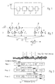
- a known cross correlation means 7 is shown in figure 2.
- the cross correlation means 7 cross correlates incoming signals y(i), e. g. coming from the IQ demodulation means 4, within a cross correlation window of a length 16.
- the cross correlation window length 16 means that the incoming digital signal y(i) is cross correlated sample by sample on the basis of a length of 16 samples.
- the cross correlation window length of 16 samples can thereby correspond to the length of a repetition pattern of the reference symbol.
- a reference symbol comprising 9 repetition patterns is shown, whereby one repetition pattern can comprise 16 samples.
- the receiving apparatus 1 knows exactly the structure of the reference symbol to be received.
- a complex conjugated version of an expected repetition pattern is stored in the synchronising means 5 and cross correlated to the received signals.
- the cross correlation means 7 of figure 2 which has a cross correlation window length of 16, comprises 15 delay means 8 arranged serially.
- the first delay means delays the incoming complex signal y(i) by one sample, which corresponds to multiplication with a factor z -1 .
- the second delay means delays the output of the first delay means again by 1 sample and so on.
- the cross correlation means 7 comprises 16 multiplication means 9 and a sum means 10.
- the delay means 8, the multiplication means 9 and the sum means 10 are arranged so that an incoming signal having a length of 16 samples is cross correlated with a complex conjugated version of the samples of a repetition pattern.
- the complex conjugated samples of the expected repetition pattern are e. g. stored in the synchronising means of the receiver and read out respectively to the multiplication means 9.
- the sum means 10 adds up all the results from the multiplication means 9, so that an output signal r(i) is obtained.
- the output signal r(i) of the sum means 10 is supplied to an absolute value calculating means 11 which calculates the absolute value of r(i) to detect a cross correlation peak.
- the cross correlation means 7 and the absolute value calculating means 11 shown in figure 2 can be comprised in the synchronising means 5 of the receiving apparatus 1 shown in figure 1.
- FIG 3 shows three different phases of a cross correlation calculation of an incoming signal.
- the correlation window 13 of the cross correlation means 7 is located on received user data, which means that only user data are cross correlated. The user data are indicated by "???". Thus, no cross correlation peak is detected.
- the correlation window 13 is exactly matching with the eighth repetition pattern S7 of the reference symbol 12, so that a corresponding cross correlation peak is detected.
- the cross correlation window 13 is again cross correlating user data "???", so that no cross correlation peak is detected.
- the reference symbol 12 shown in figure 3 comprises 9 repetition patterns S0, S1, ..., S8, which have identical shapes.
- Each of the repetition patterns comprises e. g. 16 samples, which corresponds to the cross correlation window length 16 of the cross correlation means 7 in figure 2.
- the number of repetition patterns in the reference symbol 12 and the number of samples in each repetition pattern can be changed and adopted to the respective application.
- the cross correlation mechanism requires exact knowledge on the reference symbol to be received on the receiving side. This means, that the receiving apparatus needs to know exactly the structure and number of repetition patterns to be able to recognise the last cross correlation peak, which serves for a time and frequency synchronisation. On the other hand, if one of the cross correlation peaks is not properly detected, the synchronisation fails. In mobile communication environments, in which multipath fading degrades the correlation peak detection performance, the synchronisation performance in a known receiving apparatus of the telecommunication system is thus significantly lowered.
- the object of the present invention is therefore to provide a receiving apparatus for receiving signals in a digital telecommunication and a synchronising method for synchronising a receiving apparatus in a digital telecommunication system, which provide an improved synchronisation performance and accuracy.
- the receiving apparatus for receiving signals in a digital telecommunication system comprises receiving means for receiving a reference symbol comprising at least two repetition patterns, whereby one of said at least two repetition patterns is phase shifted in relation to the other repetition pattern, and synchronising means for synchronising the receiving apparatus in the digital telecommunication system using said received reference symbol, whereby said synchronising means comprises a cross correlation means for cross correlating at least one of said two repetition patterns within a cross correlation window having a predetermined length.
- the synchronising method for synchronising a receiving apparatus in a digital telecommunication system comprises the steps of receiving a reference symbol comprising at least two repetition patterns, whereby one of said at least two repetition patterns is phase shifted in relation to the other repetition pattern, and synchronising the receiving apparatus in the digital telecommunication system using said received reference symbol, whereby at least one of said two repetition patterns is cross correlated within a cross correlation window having a predetermined length.
- the receiving apparatus and the synchronising method of the present invention thereby provide an improved cross correlation performance for time and frequency synchronisation, particularly accurate information on the synchronisation timing.
- the present invention is especially efficient for synchronisation in a mobile telecommunication environment in which multipath fading degrades the synchronisation performance and accuracy.
- the receiving apparatus and synchronising method of the present invention are applicable to single carrier systems as well as multicarrier systems, e. g. OFDM (Orthogonal Frequency Division Multiplexing) systems.
- said at least two repetition patterns are the last two repetition patterns in the reference symbol. It is to be noted, that the synchronising mechanism of the present invention only requires two repetition patterns. Since the two repetition patterns are phase shifted in relation to each other, accurate information on the synchronisation time point can be achieved by observing the cross correlation peak and the relative phase of the cross correlation peak. However, more than two repetition patterns enhance the performance.
- the phase shifted repetition pattern is phase shifted by 180° in relation to the other repetition pattern. Thereby a very accurate and reliable phase detection is possible.
- the phase change information of the two repetition patterns in the reference symbol is used in the synchronising means to detect a cross correlation peak which indicates the position of the later one of said repetition patterns.
- the correlation peak information is calculated using the phase change information of the two repetition patterns, which allows an accurate and reliable detection of the correlation peak position and thus the synchronisation time point.
- the cross correlation means has a cross correlation window length corresponding to the length of one repetition pattern, whereby an output signal of the cross correlation means is supplied to a detection means for detecting the cross correlation peak.
- the detection means advantageously comprises a delay means for delaying the output signal of the cross correlation means by one repetition pattern length and a subtraction means for subtracting the output signal of the delay means from the output signal of the cross correlation means.
- an averaging means can be comprised for smoothening the output signal of the detection means.
- a received complex data signal corresponding to the length of one repetition pattern is cross correlated in the cross correlation means and compared in the detection means to the respective succeeding data signal having a length of one repetition pattern.
- two repetition patterns are cross correlated one after the other and are then compared to detect a cross correlation peak using the corresponding phase change information.
- the cross correlation means has a cross correlation window length corresponding to the length of two repetition patterns for detecting the position of the cross correlation peak.
- the cross correlation means of the further aspect of the present invention thus directly cross correlates received data signals on the basis of the length of two repetition patterns, which leads to a more complex structure of the cross correlation means, but enables a more effective and sophisticated synchronising mechanism.
- the stored positive and the negative conjugation of the expected repetition pattern can be used for detecting the position of the cross correlation peak.
- the output signal of the cross correlation means or the detection means is supplied to a peak threshold detection means and a gap detection means, whereby the cross correlation peak detected by the cross correlation means is confirmed or not on the basis of the detection results of the peak threshold detection means and the gap detection means.
- the signal supplied to the peak threshold detection means and the gap detection means is the output signal of the detection means.
- the peak threshold detection means detects if the output signal of the cross correlation or the detection means exceeds a predetermined cross correlation peak threshold and the gap detection means detects if the output signal of the cross correlation or the detection means has been below a predetermined gap before the detected cross correlation peak.
- the output signal of the cross correlation or the detection means can be delayed in a delay means before being supplied to said gap detection means.
- the gap detection means can additionally detect if the output signal of the cross correlation or the detection means has been below the predetermined gap threshold during a predetermined gap time.
- Figure 4 shows the structure of a reference symbol 14 as example for a reference symbol structure to be used according to the present invention.
- the reference symbol 14 of figure 4 comprises 9 repetition patterns S0, S1,...S8. Each repetition pattern has a length of 16 samples s 0 , s 1 ,...s 15 . Thereby, the last repetition pattern S8 is phase-shifted by 180 degrees in relation to the other repetition patterns, which means a multiplication by (-1). Thus, the last repetition pattern S8 comprises 15 samples -s 0 , -s 1 ,...-s 15 . All repetition patterns of the reference symbol 14 have the same shape, whereby the last repetition pattern S8 is phase-inverted by 180 degrees. It is to be noted, that the reference symbol 14 can have more or less than 9 repetition patterns and that each repetition pattern can have more or less than 16 samples.
- the reference symbol 14 is shown to be embedded in a user data sequence.
- the user data are indicated by "???".
- Figure 5 shows three different phases of cross correlating a received signal having a reference symbol 14, in which the last repetition pattern S8 is phase-inverted by 180°.
- the data sequence of the three phases shown in figure 5 are for example supplied from the IQ demodulation means 4 to the synchronising means 5, whereby the synchronising means 5 is e. g. constructed as shown in figure 6.
- the cross correlation window 15 cross correlates only user data, so that no cross correlation peak is detected.
- the 8th repetition pattern S7 of the reference symbol 14 is matched by the correlation window 15, so that a cross correlation peak is detected.
- the relative phase of the cross correlation peak of the 8th repetition pattern S7 is also detected to be "+". Since the 9th repetition pattern S8 is phase-inverted by 180° in relation to the 8th repetition pattern S7, the cross correlation peak detected for the 9th repetition pattern S8 has the relative phase "-" in relation to the phase of the 8th repetition pattern S7.
- the repetition patterns S0, S1...S6 preceding the two last repetition patterns S7 and S8 have a relative phase "+".
- phase 3 of figure 5 only user data are cross correlated in the cross correlation window 15, so that no cross correlation peak is detected.
- a relative phase information can be obtained additional to the cross correlation peak information. This phase information provides additional information on the position of the last correlation peak in the reference symbol and thus a more accurate and reliable synchronisation information.
- a cross correlation means 16 and a detection means 19 are shown, which can be implemented in a first embodiment of a synchronising means 5 of a receiving apparatus 1 of the present invention, the general structure of which is shown in Figure 1.
- the structure of the cross correlation means 16 is identical to the structure of the cross correlation means 7 shown in figure 2, so that a detailed explanation is omitted.
- the cross correlation means 16 comprises 15 delay means 17 and 16 multiplication means 18 as well as a sum means for adding the outputs of the multiplication means 18.
- the cross correlation window length of the cross correlation means 16 corresponds to the length of one repetition pattern, which is e. g. 16 samples.
- a received data stream of 16 samples is cross correlated with complex conjugated samples of an expected repetition pattern stored in the receiving apparatus 1.
- the output signal r(i) of the sum means i.e. the output signal of the cross correlation means 16 is supplied to a detection means 19 for detecting the magnitude and the phase of the signal r(i) and therefore the exact position of the cross correlation peak of the last repetition pattern S8 of the reference symbol 14 can be detected (cf. figure 5).
- Figure 7 shows another arrangement of the detection means.
- the cross correlation means 16 of figure 7 corresponds to the cross correlation means 16 of figure 6.
- the detection means comprises a delay means 20 for delaying the output signal r(i) of the cross correlation means 16 by one repetition pattern length, which is e. g. 16 samples.
- the detection means 19 further comprises a subtraction means 21 for subtracting the output signal s(i) of the delay means 20 from the output signal r(i) of the cross correlation means 16.
- the absolute value of z(i) is enhanced if r(i) matches with the phase-shifted repetition pattern S8.
- the phase value (p has nothing to do with the phase shift between the repetition pattern S7 and S8, but results from a possible frequency offset between the transmitter side and the receiver side.
- z 1 (i)/z 2 (i) -j ⁇ cot( ⁇ /2).
- FIG 8 a simulation result for the absolute value of z(i) as the output signal of the structure shown in figure 7 is shown.
- the cross correlation peak is expected to be at the last sample, i.e. the time point corresponding to the last sample, of the last repetition pattern S8.
- the cross correlation peak is located at sample 144, which is the correct value.
- the cross correlation means 16 and the detection means 19 shown in figure 6 and in figure 7 enable a correct and efficient detection of the cross correlation peak.
- the cross correlation means 16 and another embodiment of the detection means of figure 7 are shown.
- the structure shown in figure 9 corresponds to the structure shown in figure 7, whereby the output of the absolute value calculating means 22 is supplied to an averaging means 23 for smoothening the absolute value of z(i) output from the means 22.
- the structure shown in figure 9 is particularly advantageous in severe noise and fading environments.
- the averaging means 23 advantageously is a moving average filter having a filter length corresponding to the length of one repetition pattern, which is for example 16 samples as shown in figure 4.
- the cross correlation structures shown in figure 7 and 9 can e. g. be implemented in the synchronising means 5 of the receiving apparatus 1 shown in figure 1.
- Figure 10 shows a simulation result for the averaged absolute value of z(i) as the output signal of the structure shown in figure 9.
- the detection of the last repetition pattern having an inverted phase as shown in figure 4 can be seen in the transition between sample 128 and sample 144.
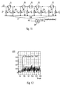
- a second embodiment of a cross correlation means 24 is shown, which can be implemented in a synchronising means 5 of a receiving apparatus 1 of the present invention, a general structure of which is e. g. shown in figure 1.
- the cross correlation means 24 essentially has the same structure as the cross correlation means 16 shown in figure 6 and the cross correlation means 7 shown in figure 2.
- the cross correlation means 24 shown in figure 11 has a cross correlation window length of two repetition patterns, which in the shown example corresponds to 32 samples, when the structure of the reference symbol shown in figure 4 is assumed.
- the cross correlation means 24 comprises 31 delay means 25, which are arranged serially and respectively cause a delay of one sample.
- the cross correlation means 24 comprises 32 multiplication means, which multiply the respective (delayed) samples of the received signal y(i) with stored positive and negative complex conjugated values of the samples of the expected repetition pattern.
- the first sample entering the cross correlation means 24 is multiplied with the first complex conjugated sample s 0 * of the expected repetition pattern.
- the second 16 samples entering the cross correlation means 24 are respectively multiplied with the stored negative complex conjugated samples -s 0 * to -s 15 * of the expected repetition pattern.
- the first sample entering the means 24 is multiplied with the negative value of the complex conjugated first sample of the expected repetition pattern -s 0 *.
- the outputs of the multiplication means 26 of the cross correlation means 24 are added up in a sum means 27, which generate an output signal z(i).
- the output signal z(i) of the sum means 27 is supplied to an absolute value calculation means 28, which calculates the absolute value of z(i).
- the output signal of the absolute value calculation means 28 therefore provides information on the magnitude as well as on the phase of the data signals, which are cross correlated by the cross correlation means 24.
- FIG 12 A simulation result for the output of the absolute value calculation means 28 of the structure shown in figure 11 is shown in figure 12.
- a reference symbol similar to the reference symbol 14 shown in figure 4 had been used, but only with 6 repetition patterns, whereby each repetition pattern consists of 16 samples.
- the phase of the last repetition pattern is shifted by 180° in relation to the other preceding repetition patterns.
- the position of the last sample of the last repetition pattern is expected to be at sample position number 96, which is clearly visible in the simulation result shown in figure 12.
- Figure 12 shows clearly, that the output signal has a maximum exactly when a correct overlapping between the two repetition patterns processed in the cross correlation means 24 is achieved.
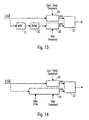
- Figure 13 shows an extended structure for increasing the reliability and accuracy of the output signal of the absolute value calculation means 22 of the structure shown in figure 7, the averaging means 23 of the structure shown in figure 9 or the absolute value calculation means 28 of the structure shown in figure 11.
- the respective output signal of the cross correlation means 24 or the detection means 19, which is the absolute value of z(i) is supplied to a peak threshold detection means 29 and a gap detection means 30.
- the peak threshold detection means 29 detects if the absolute value of z(i) exceeds a predetermined cross correlation peak threshold.
- the gap detection means 30 detects if the absolute value of z(i) has been below a predetermined gap threshold before said detected cross correlation peak.
- the gap in front of the correlation peak can be used to identify the range for the possible position of the cross correlation peak. Only when the peak threshold detection means 29 detects that the absolute value of z(i) exceeds the predetermined cross correlation threshold and the gap detection means detects that the absolute value of z(i) has been below a predetermined gap threshold before the detective cross correlation peak, the cross correlation peak is confirmed.
- the peak threshold detection means 29 and the gap detection means 30 send respectively a positive information to a determination means 33, which can for example be an AND gate, which outputs the position of the detected cross correlation peak only in case of a positive signal from both of the means 29 and 30.
- a determination means 33 which can for example be an AND gate, which outputs the position of the detected cross correlation peak only in case of a positive signal from both of the means 29 and 30.
- an averaging means 31 and/or a delay means 32 can be located.
- the averaging means 31 can for example be a moving average filter to smoothen the absolute value of z(i).
- the filter length preferably corresponds to the length of one repetition pattern of the reference symbol.
- the delay means 32 preferably provides a delay corresponding to the length of one repetition pattern of the reference symbol.
- the averaging means 31 as well as the delay means 32 can be provided or not depending on the application.
- Figure 14 shows an alternative structure to figure 13.
- the absolute value of z(i) is supplied to a peak threshold detection means 29 identical to the peak threshold detection means 29 of figure 13.
- the gap detection means 34 shown in figure 14 detects if the absolute value of z(i) has been below a predetermined gap threshold before the detected cross correlation peak and additionally detects if it has been below the predetermined gap threshold during a predetermined gap time.
- the gap detection means 34 of figure 14 checks a time period before the detected cross correlation peak.
- a determination means 33 which can for example be an AND gate, determines if the output signals from the peak threshold detection means 29 and the gap detection means 34 are both positive and confirms the detected correlation peak to be the required correlation peak for that case.
- Both structures shown in figures 13 and 14 provide an increased detection accuracy and reduce the false alarm possibility by combined detection of a presynchronisation and a correlation peak detection.
- the presynchronisation i.e. the detection of the gap in front of a detected cross correlation peak enables to detect the range of possible synchronisation peak positions, what can be used to reduce the number of computations needed for the succeeding synchronisations.
Priority Applications (18)
| Application Number | Priority Date | Filing Date | Title |
|---|---|---|---|
| DE69942353T DE69942353D1 (de) | 1999-02-24 | 1999-02-24 | Empfangsvorrichtung und Synchronisationsverfahren für ein digitales Nachrichtenübertragungssystem |
| DE69932916T DE69932916T2 (de) | 1999-02-24 | 1999-02-24 | Empfangsvorrichtung und Synchronisationsverfahren für ein digitales Nachrichtenübertragungssystem |
| EP06007831A EP1675297B1 (de) | 1999-02-24 | 1999-02-24 | Empfangsvorrichtung und Synchronisationsverfahren für ein digitales Nachrichtenübertragungssystem |
| EP99103546A EP1032157B1 (de) | 1999-02-24 | 1999-02-24 | Empfangsvorrichtung und Synchronisationsverfahren für ein digitales Nachrichtenübertragungssystem |
| AT06017363T ATE468674T1 (de) | 1999-02-24 | 1999-02-24 | Empfangsvorrichtung und synchronisationsverfahren für ein digitales nachrichtenübertragungssystem |
| EP06017363A EP1717984B1 (de) | 1999-02-24 | 1999-02-24 | Empfangsvorrichtung und Synchronisationsverfahren für ein digitales Nachrichtenübertragungssystem |
| DE69942398T DE69942398D1 (de) | 1999-02-24 | 1999-02-24 | Empfangsvorrichtung und Synchronisationsverfahren für ein digitales Nachrichtenübertragungssystem |
| US09/510,652 US7154975B1 (en) | 1999-02-24 | 2000-02-22 | Receiving apparatus and synchronizing method for a digital telecommunication system |
| KR1020000008709A KR100671723B1 (ko) | 1999-02-24 | 2000-02-23 | 디지털 통신 시스템을 위한 수신 장치 및 동기화 방법 |
| CNB001026844A CN1157075C (zh) | 1999-02-24 | 2000-02-24 | 用于数字电信系统的接收装置和同步方法 |
| JP2000052296A JP4587516B2 (ja) | 1999-02-24 | 2000-02-24 | 受信装置及び同期方法 |
| US11/429,210 US8861622B2 (en) | 1999-02-24 | 2006-05-08 | Transmitting apparatus and method for a digital telecommunication system |
| US11/498,080 US7424079B2 (en) | 1999-02-24 | 2006-08-03 | Receiving apparatus and synchronising method for a digital telecommunication system |
| US13/618,613 US20130010882A1 (en) | 1999-02-24 | 2012-09-14 | Transmitting apparatus and method for a digital telecommunication system |
| US14/037,829 US20140029698A1 (en) | 1999-02-24 | 2013-09-26 | Transmitting apparatus and method for a digital telecommunication system |
| US14/552,082 US9438289B2 (en) | 1999-02-24 | 2014-11-24 | Transmitting apparatus and method for receiving a digital signal in a digital telecommunication system |
| US14/817,862 US9450627B2 (en) | 1999-02-24 | 2015-08-04 | Transmitting apparatus and method for receiving a digital signal in a digital telecommunication system |
| US15/332,001 US20170041177A1 (en) | 1999-02-24 | 2016-10-24 | Transmitting apparatus and method for a digital telecommunication system |
Applications Claiming Priority (1)
| Application Number | Priority Date | Filing Date | Title |
|---|---|---|---|
| EP99103546A EP1032157B1 (de) | 1999-02-24 | 1999-02-24 | Empfangsvorrichtung und Synchronisationsverfahren für ein digitales Nachrichtenübertragungssystem |
Related Child Applications (2)
| Application Number | Title | Priority Date | Filing Date |
|---|---|---|---|
| EP06017363A Division EP1717984B1 (de) | 1999-02-24 | 1999-02-24 | Empfangsvorrichtung und Synchronisationsverfahren für ein digitales Nachrichtenübertragungssystem |
| EP06007831A Division EP1675297B1 (de) | 1999-02-24 | 1999-02-24 | Empfangsvorrichtung und Synchronisationsverfahren für ein digitales Nachrichtenübertragungssystem |
Publications (2)
| Publication Number | Publication Date |
|---|---|
| EP1032157A1 true EP1032157A1 (de) | 2000-08-30 |
| EP1032157B1 EP1032157B1 (de) | 2006-08-23 |
Family
ID=8237628
Family Applications (3)
| Application Number | Title | Priority Date | Filing Date |
|---|---|---|---|
| EP06017363A Expired - Lifetime EP1717984B1 (de) | 1999-02-24 | 1999-02-24 | Empfangsvorrichtung und Synchronisationsverfahren für ein digitales Nachrichtenübertragungssystem |
| EP99103546A Expired - Lifetime EP1032157B1 (de) | 1999-02-24 | 1999-02-24 | Empfangsvorrichtung und Synchronisationsverfahren für ein digitales Nachrichtenübertragungssystem |
| EP06007831A Expired - Lifetime EP1675297B1 (de) | 1999-02-24 | 1999-02-24 | Empfangsvorrichtung und Synchronisationsverfahren für ein digitales Nachrichtenübertragungssystem |
Family Applications Before (1)
| Application Number | Title | Priority Date | Filing Date |
|---|---|---|---|
| EP06017363A Expired - Lifetime EP1717984B1 (de) | 1999-02-24 | 1999-02-24 | Empfangsvorrichtung und Synchronisationsverfahren für ein digitales Nachrichtenübertragungssystem |
Family Applications After (1)
| Application Number | Title | Priority Date | Filing Date |
|---|---|---|---|
| EP06007831A Expired - Lifetime EP1675297B1 (de) | 1999-02-24 | 1999-02-24 | Empfangsvorrichtung und Synchronisationsverfahren für ein digitales Nachrichtenübertragungssystem |
Country Status (7)
| Country | Link |
|---|---|
| US (2) | US7154975B1 (de) |
| EP (3) | EP1717984B1 (de) |
| JP (1) | JP4587516B2 (de) |
| KR (1) | KR100671723B1 (de) |
| CN (1) | CN1157075C (de) |
| AT (1) | ATE468674T1 (de) |
| DE (3) | DE69942353D1 (de) |
Cited By (8)
| Publication number | Priority date | Publication date | Assignee | Title |
|---|---|---|---|---|
| EP1306995A2 (de) * | 2001-10-26 | 2003-05-02 | Microsoft Corporation | System und Verfahren zur unterabgetasteten Symbol-Synchronisation |
| DE102004059957A1 (de) * | 2004-12-13 | 2006-06-14 | Fraunhofer-Gesellschaft zur Förderung der angewandten Forschung e.V. | Synchronisationsvorrichtung und Vorrichtung zum Erzeugen eines Synchronisationssignals |
| WO2008025876A1 (en) * | 2006-08-28 | 2008-03-06 | Nokia Corporation | Synchronization |
| WO2008065419A1 (en) * | 2006-12-01 | 2008-06-05 | Plextek Limited | Narrow band receiver |
| EP2017993A1 (de) * | 2006-04-26 | 2009-01-21 | Panasonic Corporation | Signaldetektionseinrichtung und signaldetektionsverfahren |
| EP2226964A1 (de) * | 2009-03-04 | 2010-09-08 | Sony Corporation | Synchronisationsstruktur und -verfahren für eine Empfangsvorrichtung eines Kommunikationssystems |
| CN101459642B (zh) * | 2007-12-14 | 2011-09-21 | 财团法人工业技术研究院 | 适用于通信系统检测同步信号的方法与装置 |
| US8982668B2 (en) | 2010-11-15 | 2015-03-17 | Semiconductor Components Industries, Llc | Semiconductor device and method of forming same for correlation detection |
Families Citing this family (14)
| Publication number | Priority date | Publication date | Assignee | Title |
|---|---|---|---|---|
| EP1705852B1 (de) | 1999-01-08 | 2010-02-10 | Sony Deutschland Gmbh | Synchronisierungssymbolstruktur für ein OFDM-System |
| AUPR963401A0 (en) * | 2001-12-19 | 2002-01-24 | Canon Kabushiki Kaisha | Methods for the enhancement of complex peaks |
| US7751520B1 (en) * | 2003-09-17 | 2010-07-06 | Atheros Communications, Inc. | Packet detection, synchronization, and frequency offset estimation |
| EP1542421B1 (de) * | 2003-12-08 | 2010-10-27 | Panasonic Corporation | Demodulator und Demodulationsmethode und integrierter Schaltkreis des Demodulators |
| KR100582906B1 (ko) * | 2003-12-27 | 2006-05-23 | 한국전자통신연구원 | 무선 랜 시스템을 위한 프리앰블 구성 방법 및 프레임동기 검출 방법 |
| US20050265219A1 (en) * | 2004-05-11 | 2005-12-01 | Texas Instruments Incorporated | Orthogonal frequency division multiplex (OFDM) packet detect unit, method of detecting an OFDM packet and OFDM receiver employing the same |
| US7924952B2 (en) * | 2004-05-20 | 2011-04-12 | Panasonic Corporation | Signal detection device, signal detection circuit, signal detection method, and program |
| US7773662B2 (en) * | 2006-03-08 | 2010-08-10 | Renesas Technology Corporation | Synchronizing to symbols received via wireless communications channel |
| US7860128B2 (en) * | 2006-06-28 | 2010-12-28 | Samsung Electronics Co., Ltd. | System and method for wireless communication of uncompressed video having a preamble design |
| CN101656701B (zh) * | 2009-09-08 | 2012-02-08 | 清华大学 | 确定ofdm码元起始位置的方法及装置 |
| US8756031B2 (en) * | 2010-07-13 | 2014-06-17 | International Business Machines Corporation | Matched filter testing of data transmission cables |
| WO2016178469A1 (ko) * | 2015-05-05 | 2016-11-10 | 엘지전자 주식회사 | 무선 통신 시스템에서 위상 패턴 기반의 동기 신호 송수신 방법 |
| CN105450386B (zh) * | 2015-12-04 | 2018-10-26 | 天津维晟微科技有限公司 | 一种比特同步方法及装置 |
| TWI636684B (zh) * | 2017-03-15 | 2018-09-21 | 普誠科技股份有限公司 | 訊號收發裝置同步點偵測方法 |
Citations (5)
| Publication number | Priority date | Publication date | Assignee | Title |
|---|---|---|---|---|
| US4598413A (en) * | 1983-09-17 | 1986-07-01 | International Standard Electric Corporation | Circuit arrangement for frame and phase synchronization of a local sampling clock |
| US5267264A (en) * | 1991-03-18 | 1993-11-30 | Litef Gmbh | Synchronization and matching method for a binary baseband transmission system |
| EP0702467A1 (de) * | 1994-09-13 | 1996-03-20 | Laboratoires D'electronique Philips S.A.S. | Mittels Initialisierungsfolge synchronisierbares digitales Übertragungssystem |
| WO1998010421A1 (en) * | 1996-09-02 | 1998-03-12 | Philips Electronics N.V. | Fast acquisition method for obtaining data from a transmission channel and a data receiver for carrying out this method |
| EP0836294A1 (de) * | 1996-10-10 | 1998-04-15 | Compagnie Des Signaux | Übertragungssystem und Methode, um eine Änderung in der Phase für ein solches System zu detektieren |
Family Cites Families (15)
| Publication number | Priority date | Publication date | Assignee | Title |
|---|---|---|---|---|
| DE2756923C2 (de) * | 1977-12-21 | 1983-12-08 | Licentia Patent-Verwaltungs-Gmbh, 6000 Frankfurt | Anordnung zur Daten- und Nachrichtenübertragung |
| EP0235179A1 (de) * | 1985-08-30 | 1987-09-09 | Motorola, Inc. | Funkfernsprechersystem unter verwendung digitaler sprache/daten und eingebauter signalisierung |
| JPH02236171A (ja) * | 1989-01-11 | 1990-09-19 | Takeshi Nakajima | レーザドップラ流速計の流速測定装置 |
| CA2132635A1 (en) * | 1992-03-31 | 1993-10-14 | Lesley Phillip Sabel | Demultiplexer synchroniser |
| JP2731722B2 (ja) | 1994-05-26 | 1998-03-25 | 日本電気株式会社 | クロック周波数自動制御方式及びそれに用いる送信装置と受信装置 |
| SE514986C2 (sv) * | 1995-03-01 | 2001-05-28 | Telia Ab | Metod och anordning för synkronisering vid OFDM-system |
| US5629639A (en) * | 1995-06-07 | 1997-05-13 | Omnipoint Corporation | Correlation peak detector |
| SE515911C2 (sv) * | 1996-03-26 | 2001-10-29 | Ericsson Telefon Ab L M | Förfarande och anordning för mottagning av en symbolsekvens |
| JPH1065605A (ja) * | 1996-08-23 | 1998-03-06 | Sony Corp | 受信方法、タイミング検出装置及び受信装置 |
| US5991289A (en) * | 1997-08-05 | 1999-11-23 | Industrial Technology Research Institute | Synchronization method and apparatus for guard interval-based OFDM signals |
| EP1720311B1 (de) * | 1997-11-05 | 2011-06-01 | Sony Deutschland Gmbh | Synchronisierung in digitalen Kommunikationssystemen |
| JP3568182B2 (ja) * | 1997-12-03 | 2004-09-22 | 株式会社日立国際電気 | データ伝送装置の同期検出方法及びその装置 |
| JP2968962B1 (ja) * | 1998-08-19 | 1999-11-02 | 日本電信電話株式会社 | Ofdm用プリアンブル生成方法及びofdm用変調回路 |
| FI105963B (fi) * | 1998-08-24 | 2000-10-31 | Nokia Oyj | Menetelmä opetusjakson muodostamiseksi |
| JP3581324B2 (ja) * | 1998-10-29 | 2004-10-27 | 松下電器産業株式会社 | Ofdm通信装置 |
-
1999
- 1999-02-24 DE DE69942353T patent/DE69942353D1/de not_active Expired - Lifetime
- 1999-02-24 EP EP06017363A patent/EP1717984B1/de not_active Expired - Lifetime
- 1999-02-24 AT AT06017363T patent/ATE468674T1/de not_active IP Right Cessation
- 1999-02-24 DE DE69932916T patent/DE69932916T2/de not_active Expired - Lifetime
- 1999-02-24 EP EP99103546A patent/EP1032157B1/de not_active Expired - Lifetime
- 1999-02-24 EP EP06007831A patent/EP1675297B1/de not_active Expired - Lifetime
- 1999-02-24 DE DE69942398T patent/DE69942398D1/de not_active Expired - Lifetime
-
2000
- 2000-02-22 US US09/510,652 patent/US7154975B1/en not_active Expired - Lifetime
- 2000-02-23 KR KR1020000008709A patent/KR100671723B1/ko active IP Right Grant
- 2000-02-24 JP JP2000052296A patent/JP4587516B2/ja not_active Expired - Lifetime
- 2000-02-24 CN CNB001026844A patent/CN1157075C/zh not_active Expired - Lifetime
-
2006
- 2006-08-03 US US11/498,080 patent/US7424079B2/en not_active Expired - Lifetime
Patent Citations (5)
| Publication number | Priority date | Publication date | Assignee | Title |
|---|---|---|---|---|
| US4598413A (en) * | 1983-09-17 | 1986-07-01 | International Standard Electric Corporation | Circuit arrangement for frame and phase synchronization of a local sampling clock |
| US5267264A (en) * | 1991-03-18 | 1993-11-30 | Litef Gmbh | Synchronization and matching method for a binary baseband transmission system |
| EP0702467A1 (de) * | 1994-09-13 | 1996-03-20 | Laboratoires D'electronique Philips S.A.S. | Mittels Initialisierungsfolge synchronisierbares digitales Übertragungssystem |
| WO1998010421A1 (en) * | 1996-09-02 | 1998-03-12 | Philips Electronics N.V. | Fast acquisition method for obtaining data from a transmission channel and a data receiver for carrying out this method |
| EP0836294A1 (de) * | 1996-10-10 | 1998-04-15 | Compagnie Des Signaux | Übertragungssystem und Methode, um eine Änderung in der Phase für ein solches System zu detektieren |
Non-Patent Citations (1)
| Title |
|---|
| SCHAUB T ET AL: "FRAME SYNCHRONIZATION FOR SPONTANEOUS TRANSMISSIONS", COMMUNICATIONS: CONNECTING THE FUTURE, SAN DIEGO, DEC. 2- 5, 1990, vol. 1, 2 December 1990 (1990-12-02), INSTITUTE OF ELECTRICAL AND ELECTRONICS ENGINEERS, pages 617 - 622, XP000218800, ISBN: 0-87942-632-2 * |
Cited By (20)
| Publication number | Priority date | Publication date | Assignee | Title |
|---|---|---|---|---|
| US7486755B2 (en) | 2001-10-26 | 2009-02-03 | Microsoft Corporation | Method and system for undersampled symbol synchronization |
| EP1306995A3 (de) * | 2001-10-26 | 2006-02-15 | Microsoft Corporation | System und Verfahren zur unterabgetasteten Symbol-Synchronisation |
| EP1306995A2 (de) * | 2001-10-26 | 2003-05-02 | Microsoft Corporation | System und Verfahren zur unterabgetasteten Symbol-Synchronisation |
| US7653166B2 (en) | 2004-12-13 | 2010-01-26 | Fraunhofer-Gesellschaft Zur Foerderung Der Angewandten Forschung E.V. | Synchronization device and device for generating a synchronization signal |
| US7525483B2 (en) | 2004-12-13 | 2009-04-28 | Fraunhofer-Gesellschaft Zur Foerderung Der Angewandten Forschung E.V. | Receive device and method for receiving a receive sequence |
| DE102004059957A1 (de) * | 2004-12-13 | 2006-06-14 | Fraunhofer-Gesellschaft zur Förderung der angewandten Forschung e.V. | Synchronisationsvorrichtung und Vorrichtung zum Erzeugen eines Synchronisationssignals |
| EP2017993A1 (de) * | 2006-04-26 | 2009-01-21 | Panasonic Corporation | Signaldetektionseinrichtung und signaldetektionsverfahren |
| EP2017993A4 (de) * | 2006-04-26 | 2011-12-28 | Panasonic Corp | Signaldetektionseinrichtung und signaldetektionsverfahren |
| CN101523763B (zh) * | 2006-08-28 | 2012-10-17 | 诺基亚公司 | 同步 |
| WO2008025876A1 (en) * | 2006-08-28 | 2008-03-06 | Nokia Corporation | Synchronization |
| GB2456929A (en) * | 2006-08-28 | 2009-08-05 | Nokia Corp | Synchronization |
| GB2456929B (en) * | 2006-08-28 | 2010-12-29 | Nokia Corp | Synchronization |
| US7864899B2 (en) | 2006-08-28 | 2011-01-04 | Nokia Corporation | Synchronization |
| US8184748B2 (en) | 2006-12-01 | 2012-05-22 | Plextek Limited | Narrow band receiver |
| WO2008065419A1 (en) * | 2006-12-01 | 2008-06-05 | Plextek Limited | Narrow band receiver |
| EP3119030A1 (de) * | 2006-12-01 | 2017-01-18 | Telensa Holdings Limited | Schmalbandempfänger |
| CN101459642B (zh) * | 2007-12-14 | 2011-09-21 | 财团法人工业技术研究院 | 适用于通信系统检测同步信号的方法与装置 |
| EP2226964A1 (de) * | 2009-03-04 | 2010-09-08 | Sony Corporation | Synchronisationsstruktur und -verfahren für eine Empfangsvorrichtung eines Kommunikationssystems |
| US8553812B2 (en) | 2009-03-04 | 2013-10-08 | Sony Corporation | Synchronization structure and method for a receiving apparatus of a communication system |
| US8982668B2 (en) | 2010-11-15 | 2015-03-17 | Semiconductor Components Industries, Llc | Semiconductor device and method of forming same for correlation detection |
Also Published As
| Publication number | Publication date |
|---|---|
| JP4587516B2 (ja) | 2010-11-24 |
| CN1157075C (zh) | 2004-07-07 |
| KR20000062603A (ko) | 2000-10-25 |
| DE69942353D1 (de) | 2010-06-17 |
| EP1717984A1 (de) | 2006-11-02 |
| DE69942398D1 (de) | 2010-07-01 |
| US7424079B2 (en) | 2008-09-09 |
| US20060269008A1 (en) | 2006-11-30 |
| EP1675297B1 (de) | 2010-05-05 |
| US7154975B1 (en) | 2006-12-26 |
| DE69932916T2 (de) | 2007-03-29 |
| KR100671723B1 (ko) | 2007-01-22 |
| ATE468674T1 (de) | 2010-06-15 |
| EP1675297A1 (de) | 2006-06-28 |
| CN1268007A (zh) | 2000-09-27 |
| EP1032157B1 (de) | 2006-08-23 |
| DE69932916D1 (de) | 2006-10-05 |
| JP2000252971A (ja) | 2000-09-14 |
| EP1717984B1 (de) | 2010-05-19 |
Similar Documents
| Publication | Publication Date | Title |
|---|---|---|
| US7424079B2 (en) | Receiving apparatus and synchronising method for a digital telecommunication system | |
| US8023397B2 (en) | Joint packet detection in a wireless communication system with one or more receivers | |
| KR100615838B1 (ko) | 디지털 원격 통신 시스템에서 다른 데이터 버스트 형태들 사이를 구별하는 구별 방법 및 통신 장치 | |
| US7463709B2 (en) | Method and apparatus for generating a synchronization sequence in a spread spectrum communications transceiver | |
| US9450627B2 (en) | Transmitting apparatus and method for receiving a digital signal in a digital telecommunication system | |
| US8249116B2 (en) | Methods and systems for timing acquisition robust to channel fading | |
| CN101273524A (zh) | 帧同步 | |
| WO2006101489A1 (en) | Joint packet detection in a wireless communication system with one or more receiver | |
| EP1090476A1 (de) | Verfahren für dekorrelation von hintergrund-interferenzen in einem zeitsynchronisierten mobilen kommunikationssystem | |
| US11070246B2 (en) | Digital radio communication | |
| WO2001028145A1 (en) | Apparatus, and associated method, for detecting a symbol sequence | |
| EP1746742B1 (de) | Verfahren zur Schätzung der Ankunftszeit eines Zugriffsbursts, und Vorrichtung | |
| US20020122407A1 (en) | Methods, communication apparatus, and computer program products for detecting an information field in a signal by averaging symbol values across multiple time slot intervals | |
| KR100964065B1 (ko) | 통신 시스템에서의 타이밍 결정 장치 및 방법 | |
| EP2063596B1 (de) | Verbund-Paketdetektion in einem drahtlosen Kommunikationssystem mit einem oder mehreren Empfängern | |
| CN115685257A (zh) | 无线电同步 | |
| JPH07154444A (ja) | フレーム同期検出回路 | |
| US20020114310A1 (en) | Methods, communication apparatus, and computer program products for detecting an information field in a signal by averaging symbol values across multiple time slot intervals | |
| KR101126991B1 (ko) | 하나 이상의 수신기를 갖는 무선 통신 시스템에서의 조인트패킷 검출 | |
| JP3636006B2 (ja) | ディジタル伝送装置 |
Legal Events
| Date | Code | Title | Description |
|---|---|---|---|
| PUAI | Public reference made under article 153(3) epc to a published international application that has entered the european phase |
Free format text: ORIGINAL CODE: 0009012 |
|
| AK | Designated contracting states |
Kind code of ref document: A1 Designated state(s): DE ES FI FR GB IT NL SE |
|
| AX | Request for extension of the european patent |
Free format text: AL;LT;LV;MK;RO;SI |
|
| 17P | Request for examination filed |
Effective date: 20010103 |
|
| AKX | Designation fees paid |
Free format text: DE ES FI FR GB IT NL SE |
|
| RAP1 | Party data changed (applicant data changed or rights of an application transferred) |
Owner name: SONY INTERNATIONAL (EUROPE) GMBH |
|
| 17Q | First examination report despatched |
Effective date: 20040427 |
|
| RAP1 | Party data changed (applicant data changed or rights of an application transferred) |
Owner name: SONY DEUTSCHLAND GMBH |
|
| RAP1 | Party data changed (applicant data changed or rights of an application transferred) |
Owner name: SONY DEUTSCHLAND GMBH |
|
| RAP1 | Party data changed (applicant data changed or rights of an application transferred) |
Owner name: SONY DEUTSCHLAND GMBH |
|
| GRAP | Despatch of communication of intention to grant a patent |
Free format text: ORIGINAL CODE: EPIDOSNIGR1 |
|
| GRAS | Grant fee paid |
Free format text: ORIGINAL CODE: EPIDOSNIGR3 |
|
| GRAA | (expected) grant |
Free format text: ORIGINAL CODE: 0009210 |
|
| AK | Designated contracting states |
Kind code of ref document: B1 Designated state(s): DE ES FI FR GB IT NL SE |
|
| PG25 | Lapsed in a contracting state [announced via postgrant information from national office to epo] |
Ref country code: NL Free format text: LAPSE BECAUSE OF FAILURE TO SUBMIT A TRANSLATION OF THE DESCRIPTION OR TO PAY THE FEE WITHIN THE PRESCRIBED TIME-LIMIT Effective date: 20060823 Ref country code: IT Free format text: LAPSE BECAUSE OF FAILURE TO SUBMIT A TRANSLATION OF THE DESCRIPTION OR TO PAY THE FEE WITHIN THE PRESCRIBED TIME-LIMIT;WARNING: LAPSES OF ITALIAN PATENTS WITH EFFECTIVE DATE BEFORE 2007 MAY HAVE OCCURRED AT ANY TIME BEFORE 2007. THE CORRECT EFFECTIVE DATE MAY BE DIFFERENT FROM THE ONE RECORDED. Effective date: 20060823 |
|
| REG | Reference to a national code |
Ref country code: GB Ref legal event code: FG4D |
|
| REG | Reference to a national code |
Ref country code: SE Ref legal event code: TRGR |
|
| REF | Corresponds to: |
Ref document number: 69932916 Country of ref document: DE Date of ref document: 20061005 Kind code of ref document: P |
|
| PG25 | Lapsed in a contracting state [announced via postgrant information from national office to epo] |
Ref country code: ES Free format text: LAPSE BECAUSE OF FAILURE TO SUBMIT A TRANSLATION OF THE DESCRIPTION OR TO PAY THE FEE WITHIN THE PRESCRIBED TIME-LIMIT Effective date: 20061204 |
|
| NLV1 | Nl: lapsed or annulled due to failure to fulfill the requirements of art. 29p and 29m of the patents act | ||
| ET | Fr: translation filed | ||
| PLBE | No opposition filed within time limit |
Free format text: ORIGINAL CODE: 0009261 |
|
| STAA | Information on the status of an ep patent application or granted ep patent |
Free format text: STATUS: NO OPPOSITION FILED WITHIN TIME LIMIT |
|
| 26N | No opposition filed |
Effective date: 20070524 |
|
| REG | Reference to a national code |
Ref country code: FR Ref legal event code: PLFP Year of fee payment: 18 |
|
| REG | Reference to a national code |
Ref country code: GB Ref legal event code: 732E Free format text: REGISTERED BETWEEN 20161013 AND 20161019 |
|
| REG | Reference to a national code |
Ref country code: FR Ref legal event code: PLFP Year of fee payment: 19 |
|
| REG | Reference to a national code |
Ref country code: FR Ref legal event code: PLFP Year of fee payment: 20 |
|
| PGFP | Annual fee paid to national office [announced via postgrant information from national office to epo] |
Ref country code: FI Payment date: 20180219 Year of fee payment: 20 Ref country code: GB Payment date: 20180216 Year of fee payment: 20 Ref country code: DE Payment date: 20180219 Year of fee payment: 20 |
|
| PGFP | Annual fee paid to national office [announced via postgrant information from national office to epo] |
Ref country code: IT Payment date: 20180227 Year of fee payment: 20 Ref country code: FR Payment date: 20180222 Year of fee payment: 20 Ref country code: SE Payment date: 20180227 Year of fee payment: 20 |
|
| REG | Reference to a national code |
Ref country code: DE Ref legal event code: R082 Ref document number: 69932916 Country of ref document: DE Representative=s name: MITSCHERLICH, PATENT- UND RECHTSANWAELTE PARTM, DE Ref country code: DE Ref legal event code: R081 Ref document number: 69932916 Country of ref document: DE Owner name: WI-FI ONE TECHNOLOGIES INTERNATIONAL LIMITED, IE Free format text: FORMER OWNER: SONY DEUTSCHLAND GMBH, 10785 BERLIN, DE |
|
| REG | Reference to a national code |
Ref country code: GB Ref legal event code: 732E Free format text: REGISTERED BETWEEN 20190124 AND 20190130 |
|
| REG | Reference to a national code |
Ref country code: DE Ref legal event code: R071 Ref document number: 69932916 Country of ref document: DE |
|
| REG | Reference to a national code |
Ref country code: GB Ref legal event code: PE20 Expiry date: 20190223 |
|
| REG | Reference to a national code |
Ref country code: SE Ref legal event code: EUG |
|
| PG25 | Lapsed in a contracting state [announced via postgrant information from national office to epo] |
Ref country code: GB Free format text: LAPSE BECAUSE OF EXPIRATION OF PROTECTION Effective date: 20190223 |