EP1032102B1 - Verteilereinrichtung - Google Patents
Verteilereinrichtung Download PDFInfo
- Publication number
- EP1032102B1 EP1032102B1 EP00101650A EP00101650A EP1032102B1 EP 1032102 B1 EP1032102 B1 EP 1032102B1 EP 00101650 A EP00101650 A EP 00101650A EP 00101650 A EP00101650 A EP 00101650A EP 1032102 B1 EP1032102 B1 EP 1032102B1
- Authority
- EP
- European Patent Office
- Prior art keywords
- housing
- wire guidance
- wire guide
- guidance channels
- guide channels
- Prior art date
- Legal status (The legal status is an assumption and is not a legal conclusion. Google has not performed a legal analysis and makes no representation as to the accuracy of the status listed.)
- Expired - Lifetime
Links
- 238000003780 insertion Methods 0.000 description 9
- 230000037431 insertion Effects 0.000 description 9
- 238000013459 approach Methods 0.000 description 1
- 210000002105 tongue Anatomy 0.000 description 1
Images

Classifications
-
- H—ELECTRICITY
- H02—GENERATION; CONVERSION OR DISTRIBUTION OF ELECTRIC POWER
- H02G—INSTALLATION OF ELECTRIC CABLES OR LINES, OR OF COMBINED OPTICAL AND ELECTRIC CABLES OR LINES
- H02G3/00—Installations of electric cables or lines or protective tubing therefor in or on buildings, equivalent structures or vehicles
- H02G3/02—Details
- H02G3/04—Protective tubing or conduits, e.g. cable ladders or cable troughs
- H02G3/0462—Tubings, i.e. having a closed section
- H02G3/0487—Tubings, i.e. having a closed section with a non-circular cross-section
-
- H—ELECTRICITY
- H04—ELECTRIC COMMUNICATION TECHNIQUE
- H04Q—SELECTING
- H04Q1/00—Details of selecting apparatus or arrangements
- H04Q1/02—Constructional details
- H04Q1/14—Distribution frames
- H04Q1/149—Wireguides in connector blocks
Definitions
- the invention relates to a distribution device for Cable cores, especially telecommunications, signal or Control cable, with the features of the preamble of Claim 1.
- Distribution devices have the task of numerous Cable cores in a desired, individual way relocate, connect and contact each other or to separate.
- Distribution facilities become widely used in technology designed as wire guide washers and in alternating Order with connection strips on the longitudinal walls of a Mounting tray attached or snapped on. To do this the wire guide washers holding the Fastening approaches, for example tongues or slots, the assembly tub interact.
- a distribution device is known from EP 0 647 072 A2 known in which a pair of wire guide washers in common a box-shaped housing made of the same shape Form the housing halves.
- the case has the first Wire guide channels that run from one side of the housing to the Front run and second wire guide channels that from the opposite side of the case to the front run.
- the first and second wire guide channels are arched and serve to thread the Wires or cable cores.
- the individual wire guide channels have defined ones Dimensions related to the width and height that on the usual cable cores are matched. Often, however, come also thicker cable cores are used, either one on the connecting device snapped on supplied, or to be removed from this. For In this case, distribution facilities are used, which consist of housing halves of identical shape to one another Wire guide channels of larger dimensions are formed.
- DE 29 01 766 A1 describes an isolating distributor for electrical systems, in particular telephone systems with one Housing on which on opposite sides starting from opposite sides of wire guide channels each run to the front of the distributor.
- the invention has for its object a Propose distribution device for cable cores that dish different Can accommodate cable cores and cable diameter. This task is done with a distribution facility for Cable cores solved with the features of claim 1.
- the invention is based on the idea of a Distribution device with first and second Provide wire guide channels, the first Wire guide channels have a larger passage cross section have than the second wire guide channels. This will it is possible to target from one side of the housing Distribution device to introduce thicker cable cores while continue on the opposite side of the case Small diameter cable cores in the wire guide channels with smaller passage cross sections.
- the housing is therefore not of the same shape Housing halves formed, but a housing that big Channels on one side and small on the other Channels combined.
- This design of the housing has the advantage that on the one hand sufficiently large channels for routing cable cores with a large cable diameter are present, on the other hand when guiding cable cores no space is wasted with a small cable diameter.
- the first wire guide channels and / or the second wire guide channels have an arcuate course. Since the outlet openings of the wire guide channels in the housing of the distributor device are in each case on the front and one side of the housing, a change in direction, which can have different geometries, must take place in the longitudinal course of the wire guide channel between the two outlet openings.
- An arched course represents a harmonious form of change of direction for the threading of the cable wires.
- the distributor device furthermore fastening devices, which are located on the back of the housing and for Serve on a mounting tray. This leaves the distribution device firmly on the mounting tray attach and fix.
- the distributor device preferably further comprises Holding means for attaching a terminal block. This allows together with the fastening device Attachment to a mounting tub a firm bond between the terminal block and the mounting tray.
- the distributor device preferably further comprises tooth-shaped gradations in the opening area of the first Wire guide channel and / or the second wire guide channel. These tooth-shaped gradations serve as an insertion aid in the Area of entry openings for those through the Wire guide ducts to be threaded through.
- the Wire guide channels a linear insertion area and / or a linear execution area.
- This particular geometry with linear entry and exit areas and one-each arc tangential to the linear areas constant radius of curvature forms a particularly suitable one Geometry for threading cable wires or wire pairs to facilitate.
- the angle between the insertion direction and is preferably the direction of execution greater than 90 °, preferably between 95 ° and 110 °. This takes into account the direction of the cable side incoming cable cores that can easily be Distribution device are introduced. By choosing the Angle between the direction of insertion and the direction of execution A particularly harmonious course is thus greater than 90 ° of the cable cores and pairs.
- the Cross-sectional area of the wire guide channels from the side of the Housing towards the front of the housing is made easier by due to the enlarging cross-sectional area as it progresses Insertion prevents kinking and pinching of the cable wires is progressively leaving more room for those to be threaded through Cable cores is available.
- the Contact between the cable wires to be inserted with the Walls of the wire guide channels reduced, which reduces friction and further facilitates insertion becomes.
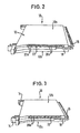
- Figures 2 and 3 is a perspective view View of the distribution device 10 from different Pages shown. This means that the one in Fig. 2 above not shown side surface 12a of the housing 12 in Fig. 3 is visible and instead the opposite directed side surface 12b in Fig. 3 lies above.
- the distributor device 10 has fastening devices 14 on the rear side , which are used for fastening on holding rails or a mounting trough.
- the geometry of the fasteners 14 is for that Understanding and essence of the invention are irrelevant, since only are ensured by the fastening devices is that the distribution device 10 on a suitable Profile, e.g. a mounting tray, attachable, preferably can be snapped on.
- a suitable Profile e.g. a mounting tray, attachable
- a connection strip 16 is shown on the front of the distributor device. This is plugged onto the front of the distributor device 10, the latching hooks 18 of the terminal block shown in FIGS. 2 and 3 interacting with corresponding holding means of the distributor device.
- openings 20a, 20b On the respective sides of that shown in Figs. 2 and 3 Distribution device are openings 20a, 20b, the serve the entry or exit of cable cores. How out a comparison of FIGS. 2 and 3 can be seen the openings 20a visible in the view according to FIG. 2 each have a smaller cross-sectional area than that in the 3 visible openings 20b. So that is not shown in Figs. 2 and 3 formed from halves of the same shape, but with equipped with different wire guide channels Cross section remains approximately constant over the course and whose opening cross sections 20a, 20b in FIGS. 2 and 3 are shown.
- the wire guide channels shown in more detail in FIG. 1 run from the openings 20a, 20b along the side edges of the distributor device in an arc shape to outlet openings on the front side .
- these have a course that causes a change in direction of 90 ° of the cable wires when threading cable wires.
- the openings 20b shown in FIG. 3 subsequent wire guide channels with larger Passage cross-section are used for the passage of cable cores with a larger cross-section, while in Fig. 2 in opening area 20a shown wire guide channels for Suitable for cable cores with smaller cross-sectional dimensions are.
- FIGS. 2 and 3 are from the side visible in FIG Distribution device made of double channels for switching purposes passed through the distribution device. So are double many wire guide channels from the side visible in Fig. 2 out through the distribution device as from the in Fig. 3 visible side.
- Distribution device specifically the use of special, thicker cable cores or cable pairs can be provided. Of course, thinner cable cores can also be introduced.
- FIGS. 2 and 3 are for Insertion aid the side edges 22 in the area of the in Fig. 2nd and 3 visible entry openings 20a, 20b with provided tooth-shaped steps. While on the in Fig. 3 visible side the gradations only over one single wire guide channel are guided in the in Fig. 2 visible side edge, the gradations each over two adjacent wire guide channels led away. About the Gradations can also be done in poor visibility the position of the opening of a desired wire guide channel easily identify.
- Fig. 1 the wall part 26 of the distributor device is included the formed therein, in the illustration according to FIG. 1 Open wire guide channels 32 shown above.
- the Wire guide channels are through an intermediate wall part closed so that a substantially rectangular Cross section of the wire guide channels 32 results.
- This in 1 wall part 26 belongs to the housing half, whose opening side is shown in Fig. 2.
- Between Wire guide channels 32 are walls 34 for lateral limitation of the individual wire guide channels and for the orderly feeding of the cable wires or wire pairs to the Terminal strips or shoulders.
- eyelets 30 are provided in FIG. 1, on the one hand the incoming cable wires or wire pairs and on the other hand the corresponding outgoing cable wires or wire pairs bundle and manage.
- the wire guide channels can either have an arcuate course with a uniform radius of curvature along their course, or else, as shown in FIG. 1, initially an essentially linear inlet area 40, which is followed by an area 42 with a uniform radius of curvature.
- the exact geometry of the wire guide channels depends on the requirement for the simple and uncomplicated insertion of the cable wires or wire pairs through the wire guide channels.
- the angle between the direction of insertion (arrow direction A) and the direction of exit (arrow B) is preferably greater than 90 °.
- the distributor device according to the invention offers the advantage that specifically thicker cable cores with thinner cable cores can be combined by for the respectively required Cable cross-sections appropriately dimensioned Wire guide channels are provided.
Landscapes
- Engineering & Computer Science (AREA)
- Computer Networks & Wireless Communication (AREA)
- Architecture (AREA)
- Civil Engineering (AREA)
- Structural Engineering (AREA)
- Installation Of Indoor Wiring (AREA)
- Structure Of Telephone Exchanges (AREA)
- Laying Of Electric Cables Or Lines Outside (AREA)
- Paper (AREA)
- Physical Deposition Of Substances That Are Components Of Semiconductor Devices (AREA)
- Details Of Television Systems (AREA)
- Magnetic Resonance Imaging Apparatus (AREA)
- Devices For Checking Fares Or Tickets At Control Points (AREA)
- Transition And Organic Metals Composition Catalysts For Addition Polymerization (AREA)
- Acyclic And Carbocyclic Compounds In Medicinal Compositions (AREA)
- Discharge Of Articles From Conveyors (AREA)
- Patch Boards (AREA)
- Details Of Indoor Wiring (AREA)
- Input Circuits Of Receivers And Coupling Of Receivers And Audio Equipment (AREA)
- Platform Screen Doors And Railroad Systems (AREA)
Description
- Fig. 1
- einen Schnitt durch die Drahtführungskanäle einer Verteilereinrichtung zeigt; und
- Fig. 2 und 3
- jeweils perspektivische Seitenansichten der erfindungsgemäßen Verteilereinrichtung darstellen.
Claims (8)
- Verteilereinrichtung (10) für Kabel, insbesondere Fernmelde-, Signal- oder Steuerkabel, mit einem Gehäuse (12), das eine Vorderseite aufweist, wobei in dem Gehäusedadurch gekennzeichnet, daß die ersten Drahtführungskanäle einen größeren Durchtrittsquerschnitt (20b) aufweisen als die zweiten Drahtführungskanäle, wobei doppelt so viele zweite Drahtführungskanäle vorhanden sind als erste Drahtführungkanäle.erste Drahtführungskanäle von einer ersten Seite des Gehäuses (12) zur Vorderseite des Gehäuses verlaufen; undzweite Drahtführungskanäle von einer zweiten, zur ersten Seite entgegengesetzten Seite zur Vorderseite des Gehäuses verlaufen;
- Verteilereinrichtung nach Anspruch 1,
dadurch gekennzeichnet, daß die ersten Drahtführungskanäle und/oder die zweiten Drahtführungskanäle einen bogenförmigen Verlauf besitzen. - Verteilereinrichtung nach Anspruch 1 oder 2, weiter umfassend Befestigungseinrichtungen (14), die sich an der Rückseite des Gehäuses (10) befinden und zur Anbringung auf einer Montagewanne dienen.
- Verteilereinrichtung nach einem der Ansprüche 1 bis 3, weiter umfassend Haltemittel (18) zur Anbringung einer Anschlußleiste.
- Verteilereinrichtung nach einem oder mehreren der Ansprüche 1 bis 4, weiter umfassend zahnförmige Abstufungen (22) im öffnungsbereich (20a, 20b) des ersten Drahtführungskanals und/oder des zweiten Drahtführungskanals.
- Verteilereinrichtung nach einem der vorhergehenden Ansprüche,
dadurch gekennzeichnet, daß
die Drahtführungskanäle einen linearen Einführbereich (40) und/oder einen linearen Ausführbereich besitzen. - Verteilereinrichtung nach Anspruch 6,
dadurch gekennzeichnet, daß
der Winkel zwischen der Einführrichtung und der Ausführrichtung größer als 90°, vorzugsweise zwischen 95° und 110° ist. - Verteilereinrichtung nach einem der vorhergehenden Ansprüche,
dadurch gekennzeichnet,daß
sich die Querschnittsfläche der Drahtführungskanäle von der Seite des Gehäuses zur Vorderseite des Gehäuses vergrößert.
Priority Applications (1)
| Application Number | Priority Date | Filing Date | Title |
|---|---|---|---|
| EP02023618A EP1276196A1 (de) | 1999-02-26 | 2000-02-01 | Verteilereinrichtung |
Applications Claiming Priority (2)
| Application Number | Priority Date | Filing Date | Title |
|---|---|---|---|
| DE29903518U | 1999-02-26 | ||
| DE29903518U DE29903518U1 (de) | 1999-02-26 | 1999-02-26 | Verteilereinrichtung |
Related Child Applications (1)
| Application Number | Title | Priority Date | Filing Date |
|---|---|---|---|
| EP02023618A Division EP1276196A1 (de) | 1999-02-26 | 2000-02-01 | Verteilereinrichtung |
Publications (3)
| Publication Number | Publication Date |
|---|---|
| EP1032102A2 EP1032102A2 (de) | 2000-08-30 |
| EP1032102A3 EP1032102A3 (de) | 2000-11-29 |
| EP1032102B1 true EP1032102B1 (de) | 2003-05-07 |
Family
ID=8070031
Family Applications (2)
| Application Number | Title | Priority Date | Filing Date |
|---|---|---|---|
| EP02023618A Ceased EP1276196A1 (de) | 1999-02-26 | 2000-02-01 | Verteilereinrichtung |
| EP00101650A Expired - Lifetime EP1032102B1 (de) | 1999-02-26 | 2000-02-01 | Verteilereinrichtung |
Family Applications Before (1)
| Application Number | Title | Priority Date | Filing Date |
|---|---|---|---|
| EP02023618A Ceased EP1276196A1 (de) | 1999-02-26 | 2000-02-01 | Verteilereinrichtung |
Country Status (8)
| Country | Link |
|---|---|
| EP (2) | EP1276196A1 (de) |
| AT (1) | ATE239993T1 (de) |
| AU (1) | AU756261B2 (de) |
| DE (2) | DE29903518U1 (de) |
| ES (1) | ES2193013T3 (de) |
| PL (1) | PL193748B1 (de) |
| PT (1) | PT1032102E (de) |
| ZA (1) | ZA200000703B (de) |
Families Citing this family (6)
| Publication number | Priority date | Publication date | Assignee | Title |
|---|---|---|---|---|
| DE20200746U1 (de) * | 2002-01-18 | 2002-04-04 | 3M Innovative Properties Co., St. Paul, Minn. | Anschlussblock und Verteilereinrichtung mit einem Anschlussblock |
| EP1800497B1 (de) * | 2004-10-12 | 2009-05-27 | CCS Technology, Inc. | Verteilereinrichtung einer telekommunikationsanlage sowie drahtführungselement für eine verteilereinrichtung |
| ES2372177T3 (es) | 2004-11-24 | 2012-01-16 | 3M Innovative Properties Company | Módulo de telecomunicaciones, combinación de un módulo de telecomunicaciones y al menos un circuito divisor, y conjunto de al menos dos módulos de telecomunicaciones. |
| US20070082522A1 (en) | 2005-10-11 | 2007-04-12 | Pierre Bonvallat | Carrier and an assembly including a carrier and a telecommunications module |
| DE202007001342U1 (de) * | 2007-01-24 | 2007-04-05 | CCS Technology, Inc., Wilmington | Verteilereinrichtung einer Telekommunikationsanlage |
| CN111864672B (zh) * | 2020-07-08 | 2025-04-01 | 江苏海纬集团有限公司 | 一种耐冲压穿线盒 |
Family Cites Families (5)
| Publication number | Priority date | Publication date | Assignee | Title |
|---|---|---|---|---|
| DE2901766C2 (de) * | 1979-01-18 | 1982-05-19 | Telefonbau Und Normalzeit Gmbh, 6000 Frankfurt | Trennverteiler für elektrische Anlagen, insbesondere Fernsprechanlagen |
| FR2550042B1 (fr) * | 1983-07-29 | 1985-11-22 | Ctm | Dispositif de raccordement modulaire pour repartiteur telephonique |
| NZ216143A (en) * | 1985-06-03 | 1989-04-26 | Adc Telecommunications Inc | Distribution frame wire connection module with insertable overvoltage protector |
| DE59410263D1 (de) * | 1993-09-06 | 2003-05-08 | Quante Ag | Verteilereinrichtung für Fernmelde-, Signal-, Steuerkabel od. dgl. |
| DE19537529C1 (de) * | 1995-09-29 | 1997-03-06 | Krone Ag | Verteilerleiste für die Telekommunikations- und Datentechnik |
-
1999
- 1999-02-26 DE DE29903518U patent/DE29903518U1/de not_active Expired - Lifetime
-
2000
- 2000-02-01 DE DE50002034T patent/DE50002034D1/de not_active Expired - Lifetime
- 2000-02-01 ES ES00101650T patent/ES2193013T3/es not_active Expired - Lifetime
- 2000-02-01 EP EP02023618A patent/EP1276196A1/de not_active Ceased
- 2000-02-01 EP EP00101650A patent/EP1032102B1/de not_active Expired - Lifetime
- 2000-02-01 PT PT00101650T patent/PT1032102E/pt unknown
- 2000-02-01 AT AT00101650T patent/ATE239993T1/de not_active IP Right Cessation
- 2000-02-07 AU AU14954/00A patent/AU756261B2/en not_active Ceased
- 2000-02-14 ZA ZA200000703A patent/ZA200000703B/xx unknown
- 2000-02-24 PL PL338594A patent/PL193748B1/pl not_active IP Right Cessation
Also Published As
| Publication number | Publication date |
|---|---|
| EP1032102A2 (de) | 2000-08-30 |
| EP1032102A3 (de) | 2000-11-29 |
| PT1032102E (pt) | 2003-09-30 |
| PL338594A1 (en) | 2000-08-28 |
| ES2193013T3 (es) | 2003-11-01 |
| ATE239993T1 (de) | 2003-05-15 |
| AU1495400A (en) | 2000-08-31 |
| DE50002034D1 (de) | 2003-06-12 |
| EP1276196A1 (de) | 2003-01-15 |
| DE29903518U1 (de) | 1999-05-27 |
| ZA200000703B (en) | 2000-09-08 |
| PL193748B1 (pl) | 2007-03-30 |
| AU756261B2 (en) | 2003-01-09 |
Similar Documents
| Publication | Publication Date | Title |
|---|---|---|
| DE19860812B4 (de) | Kabelkanalsystem zum Verlegen von Lichtwellenleiterkabeln | |
| DE3711675C2 (de) | ||
| DE112017002876B4 (de) | Kabelbaum | |
| DE102009005370A1 (de) | Elektrisches Verteilergehäuse für Kraftfahrzeuge | |
| DE19940971A1 (de) | Sammelschiene für elektr. Leiter | |
| EP1276196A1 (de) | Verteilereinrichtung | |
| DE202011000244U1 (de) | Verteilerblock | |
| DE4318015C1 (de) | Kabelanschlußkasten | |
| DE102017116679A1 (de) | Kabelkanal | |
| WO2011128306A1 (de) | Unterverteilerblock | |
| DE19626205C2 (de) | Kabelanschlußkasten | |
| DE102016103516B4 (de) | Profilleiste | |
| DE3841825C2 (de) | ||
| EP2982013B1 (de) | Schaltschrankanordnung mit verbundenen schutzbereichen | |
| DE29903000U1 (de) | Isoliergehäuse für Verteilerklemme | |
| DE19621194A1 (de) | Elektrisches Installationsgerät und Anschlußklemme für das Installationsgerät | |
| DE102024125456B3 (de) | Gehäuse, beispielsweise für einen Glasfaser-Netzverteiler oder Anschlusskasten, und Verfahren zum Installieren eines Gehäuses | |
| DE1235401B (de) | Rinne zur Verlegung elektrischer Leitungen | |
| EP4208654B1 (de) | Energieführungskette mit leitungsschonender innenaufteilung sowie kettenglied und rahmenmodul hierfür | |
| EP0121221B1 (de) | Rangierleiste mit einer Mehrzahl von den abisolierfreien Anschluss elektrischer Leiter gestattenden Doppelanschlussklemmen | |
| AT405579B (de) | Elektrokabel | |
| WO1997015971A2 (de) | Abgangs- und gerätekasten eines energieverteilsystems | |
| DE9308110U1 (de) | Kabelanschlußkasten | |
| DE3838698C2 (de) | Anordnung zur Kabelüberführung zwischen einer Tür und einem Türschacht in einer Fahrzeugkarosserie | |
| DE3311694A1 (de) | Rangierleiste mit einer mehrzahl von den abisolierfreien anschluss elektrischer leiter gestattenden doppelanschlussklemmen |
Legal Events
| Date | Code | Title | Description |
|---|---|---|---|
| PUAI | Public reference made under article 153(3) epc to a published international application that has entered the european phase |
Free format text: ORIGINAL CODE: 0009012 |
|
| AK | Designated contracting states |
Kind code of ref document: A2 Designated state(s): AT BE CH CY DE DK ES FI FR GB GR IE IT LI LU MC NL PT SE |
|
| AX | Request for extension of the european patent |
Free format text: AL;LT;LV;MK;RO;SI |
|
| PUAL | Search report despatched |
Free format text: ORIGINAL CODE: 0009013 |
|
| AK | Designated contracting states |
Kind code of ref document: A3 Designated state(s): AT BE CH CY DE DK ES FI FR GB GR IE IT LI LU MC NL PT SE |
|
| AX | Request for extension of the european patent |
Free format text: AL;LT;LV;MK;RO;SI |
|
| RIC1 | Information provided on ipc code assigned before grant |
Free format text: 7H 02G 3/04 A, 7H 04Q 1/14 B, 7H 02G 3/08 B |
|
| 17P | Request for examination filed |
Effective date: 20010125 |
|
| AKX | Designation fees paid |
Free format text: AT BE CH CY DE DK ES FI FR GB GR IE IT LI LU MC NL PT SE |
|
| AXX | Extension fees paid |
Free format text: RO PAYMENT 20010125 |
|
| 17Q | First examination report despatched |
Effective date: 20020122 |
|
| GRAH | Despatch of communication of intention to grant a patent |
Free format text: ORIGINAL CODE: EPIDOS IGRA |
|
| GRAH | Despatch of communication of intention to grant a patent |
Free format text: ORIGINAL CODE: EPIDOS IGRA |
|
| GRAA | (expected) grant |
Free format text: ORIGINAL CODE: 0009210 |
|
| AK | Designated contracting states |
Designated state(s): AT BE CH CY DE DK ES FI FR GB GR IE IT LI LU MC NL PT SE |
|
| AX | Request for extension of the european patent |
Extension state: RO |
|
| PG25 | Lapsed in a contracting state [announced via postgrant information from national office to epo] |
Ref country code: CY Free format text: LAPSE BECAUSE OF FAILURE TO SUBMIT A TRANSLATION OF THE DESCRIPTION OR TO PAY THE FEE WITHIN THE PRESCRIBED TIME-LIMIT Effective date: 20030507 |
|
| REG | Reference to a national code |
Ref country code: GB Ref legal event code: FG4D Free format text: NOT ENGLISH |
|
| REG | Reference to a national code |
Ref country code: CH Ref legal event code: EP Ref country code: CH Ref legal event code: NV Representative=s name: E. BLUM & CO. PATENTANWAELTE |
|
| REG | Reference to a national code |
Ref country code: SE Ref legal event code: TRGR |
|
| REG | Reference to a national code |
Ref country code: IE Ref legal event code: FG4D Free format text: GERMAN |
|
| REF | Corresponds to: |
Ref document number: 50002034 Country of ref document: DE Date of ref document: 20030612 Kind code of ref document: P |
|
| GBT | Gb: translation of ep patent filed (gb section 77(6)(a)/1977) | ||
| PG25 | Lapsed in a contracting state [announced via postgrant information from national office to epo] |
Ref country code: DK Free format text: LAPSE BECAUSE OF FAILURE TO SUBMIT A TRANSLATION OF THE DESCRIPTION OR TO PAY THE FEE WITHIN THE PRESCRIBED TIME-LIMIT Effective date: 20030807 Ref country code: GR Free format text: LAPSE BECAUSE OF FAILURE TO SUBMIT A TRANSLATION OF THE DESCRIPTION OR TO PAY THE FEE WITHIN THE PRESCRIBED TIME-LIMIT Effective date: 20030807 |
|
| REG | Reference to a national code |
Ref country code: PT Ref legal event code: SC4A Free format text: AVAILABILITY OF NATIONAL TRANSLATION Effective date: 20030718 |
|
| ET | Fr: translation filed | ||
| REG | Reference to a national code |
Ref country code: ES Ref legal event code: FG2A Ref document number: 2193013 Country of ref document: ES Kind code of ref document: T3 |
|
| PGFP | Annual fee paid to national office [announced via postgrant information from national office to epo] |
Ref country code: NL Payment date: 20040116 Year of fee payment: 5 |
|
| PGFP | Annual fee paid to national office [announced via postgrant information from national office to epo] |
Ref country code: PT Payment date: 20040128 Year of fee payment: 5 |
|
| PG25 | Lapsed in a contracting state [announced via postgrant information from national office to epo] |
Ref country code: AT Free format text: LAPSE BECAUSE OF NON-PAYMENT OF DUE FEES Effective date: 20040201 Ref country code: FI Free format text: LAPSE BECAUSE OF NON-PAYMENT OF DUE FEES Effective date: 20040201 Ref country code: LU Free format text: LAPSE BECAUSE OF NON-PAYMENT OF DUE FEES Effective date: 20040201 |
|
| PG25 | Lapsed in a contracting state [announced via postgrant information from national office to epo] |
Ref country code: IE Free format text: LAPSE BECAUSE OF NON-PAYMENT OF DUE FEES Effective date: 20040202 |
|
| PGFP | Annual fee paid to national office [announced via postgrant information from national office to epo] |
Ref country code: SE Payment date: 20040219 Year of fee payment: 5 |
|
| PG25 | Lapsed in a contracting state [announced via postgrant information from national office to epo] |
Ref country code: MC Free format text: LAPSE BECAUSE OF NON-PAYMENT OF DUE FEES Effective date: 20040228 |
|
| PG25 | Lapsed in a contracting state [announced via postgrant information from national office to epo] |
Ref country code: CH Free format text: LAPSE BECAUSE OF NON-PAYMENT OF DUE FEES Effective date: 20040229 Ref country code: LI Free format text: LAPSE BECAUSE OF NON-PAYMENT OF DUE FEES Effective date: 20040229 |
|
| PLBE | No opposition filed within time limit |
Free format text: ORIGINAL CODE: 0009261 |
|
| STAA | Information on the status of an ep patent application or granted ep patent |
Free format text: STATUS: NO OPPOSITION FILED WITHIN TIME LIMIT |
|
| 26N | No opposition filed |
Effective date: 20040210 |
|
| REG | Reference to a national code |
Ref country code: CH Ref legal event code: PL |
|
| REG | Reference to a national code |
Ref country code: IE Ref legal event code: MM4A |
|
| PG25 | Lapsed in a contracting state [announced via postgrant information from national office to epo] |
Ref country code: SE Free format text: LAPSE BECAUSE OF NON-PAYMENT OF DUE FEES Effective date: 20050202 |
|
| PG25 | Lapsed in a contracting state [announced via postgrant information from national office to epo] |
Ref country code: PT Free format text: LAPSE BECAUSE OF NON-PAYMENT OF DUE FEES Effective date: 20050801 |
|
| PG25 | Lapsed in a contracting state [announced via postgrant information from national office to epo] |
Ref country code: NL Free format text: LAPSE BECAUSE OF NON-PAYMENT OF DUE FEES Effective date: 20050901 |
|
| REG | Reference to a national code |
Ref country code: PT Ref legal event code: MM4A Effective date: 20050801 |
|
| EUG | Se: european patent has lapsed | ||
| NLV4 | Nl: lapsed or anulled due to non-payment of the annual fee |
Effective date: 20050901 |
|
| PGFP | Annual fee paid to national office [announced via postgrant information from national office to epo] |
Ref country code: ES Payment date: 20080226 Year of fee payment: 9 |
|
| PGFP | Annual fee paid to national office [announced via postgrant information from national office to epo] |
Ref country code: GB Payment date: 20080227 Year of fee payment: 9 Ref country code: IT Payment date: 20080226 Year of fee payment: 9 |
|
| PGFP | Annual fee paid to national office [announced via postgrant information from national office to epo] |
Ref country code: FR Payment date: 20080218 Year of fee payment: 9 |
|
| PGFP | Annual fee paid to national office [announced via postgrant information from national office to epo] |
Ref country code: BE Payment date: 20080306 Year of fee payment: 9 |
|
| BERE | Be: lapsed |
Owner name: *QUANTE A.G. Effective date: 20090228 |
|
| GBPC | Gb: european patent ceased through non-payment of renewal fee |
Effective date: 20090201 |
|
| REG | Reference to a national code |
Ref country code: FR Ref legal event code: ST Effective date: 20091030 |
|
| PG25 | Lapsed in a contracting state [announced via postgrant information from national office to epo] |
Ref country code: BE Free format text: LAPSE BECAUSE OF NON-PAYMENT OF DUE FEES Effective date: 20090228 |
|
| REG | Reference to a national code |
Ref country code: ES Ref legal event code: FD2A Effective date: 20090202 |
|
| PG25 | Lapsed in a contracting state [announced via postgrant information from national office to epo] |
Ref country code: FR Free format text: LAPSE BECAUSE OF NON-PAYMENT OF DUE FEES Effective date: 20090302 Ref country code: GB Free format text: LAPSE BECAUSE OF NON-PAYMENT OF DUE FEES Effective date: 20090201 |
|
| PG25 | Lapsed in a contracting state [announced via postgrant information from national office to epo] |
Ref country code: ES Free format text: LAPSE BECAUSE OF NON-PAYMENT OF DUE FEES Effective date: 20090202 |
|
| PG25 | Lapsed in a contracting state [announced via postgrant information from national office to epo] |
Ref country code: IT Free format text: LAPSE BECAUSE OF NON-PAYMENT OF DUE FEES Effective date: 20090201 |
|
| PGFP | Annual fee paid to national office [announced via postgrant information from national office to epo] |
Ref country code: DE Payment date: 20130131 Year of fee payment: 14 |
|
| REG | Reference to a national code |
Ref country code: DE Ref legal event code: R119 Ref document number: 50002034 Country of ref document: DE |
|
| REG | Reference to a national code |
Ref country code: DE Ref legal event code: R119 Ref document number: 50002034 Country of ref document: DE Effective date: 20140902 |
|
| PG25 | Lapsed in a contracting state [announced via postgrant information from national office to epo] |
Ref country code: DE Free format text: LAPSE BECAUSE OF NON-PAYMENT OF DUE FEES Effective date: 20140902 |