EP1031786A1 - Projecteur de véhicule capable d'émettre deux faisceaux lumineux différents avec une source unique - Google Patents
Projecteur de véhicule capable d'émettre deux faisceaux lumineux différents avec une source unique Download PDFInfo
- Publication number
- EP1031786A1 EP1031786A1 EP00400123A EP00400123A EP1031786A1 EP 1031786 A1 EP1031786 A1 EP 1031786A1 EP 00400123 A EP00400123 A EP 00400123A EP 00400123 A EP00400123 A EP 00400123A EP 1031786 A1 EP1031786 A1 EP 1031786A1
- Authority
- EP
- European Patent Office
- Prior art keywords
- axis
- reflector
- projector according
- rotation
- parts
- Prior art date
- Legal status (The legal status is an assumption and is not a legal conclusion. Google has not performed a legal analysis and makes no representation as to the accuracy of the status listed.)
- Granted
Links
- 238000006073 displacement reaction Methods 0.000 claims description 3
- 230000001131 transforming effect Effects 0.000 claims description 2
- 238000005286 illumination Methods 0.000 claims 1
- 239000011521 glass Substances 0.000 abstract description 2
- 230000007246 mechanism Effects 0.000 description 4
- 210000005069 ears Anatomy 0.000 description 2
- BASFCYQUMIYNBI-UHFFFAOYSA-N platinum Chemical compound [Pt] BASFCYQUMIYNBI-UHFFFAOYSA-N 0.000 description 2
- 239000000470 constituent Substances 0.000 description 1
- 230000000694 effects Effects 0.000 description 1
- 238000004519 manufacturing process Methods 0.000 description 1
- 238000000034 method Methods 0.000 description 1
- 230000004048 modification Effects 0.000 description 1
- 238000012986 modification Methods 0.000 description 1
- 238000005375 photometry Methods 0.000 description 1
- 230000009467 reduction Effects 0.000 description 1
- 230000000284 resting effect Effects 0.000 description 1
- 230000001052 transient effect Effects 0.000 description 1
- 230000007704 transition Effects 0.000 description 1
Images


Classifications
-
- B—PERFORMING OPERATIONS; TRANSPORTING
- B60—VEHICLES IN GENERAL
- B60Q—ARRANGEMENT OF SIGNALLING OR LIGHTING DEVICES, THE MOUNTING OR SUPPORTING THEREOF OR CIRCUITS THEREFOR, FOR VEHICLES IN GENERAL
- B60Q1/00—Arrangement of optical signalling or lighting devices, the mounting or supporting thereof or circuits therefor
- B60Q1/02—Arrangement of optical signalling or lighting devices, the mounting or supporting thereof or circuits therefor the devices being primarily intended to illuminate the way ahead or to illuminate other areas of way or environments
- B60Q1/04—Arrangement of optical signalling or lighting devices, the mounting or supporting thereof or circuits therefor the devices being primarily intended to illuminate the way ahead or to illuminate other areas of way or environments the devices being headlights
- B60Q1/14—Arrangement of optical signalling or lighting devices, the mounting or supporting thereof or circuits therefor the devices being primarily intended to illuminate the way ahead or to illuminate other areas of way or environments the devices being headlights having dimming means
- B60Q1/1415—Dimming circuits
-
- F—MECHANICAL ENGINEERING; LIGHTING; HEATING; WEAPONS; BLASTING
- F21—LIGHTING
- F21S—NON-PORTABLE LIGHTING DEVICES; SYSTEMS THEREOF; VEHICLE LIGHTING DEVICES SPECIALLY ADAPTED FOR VEHICLE EXTERIORS
- F21S41/00—Illuminating devices specially adapted for vehicle exteriors, e.g. headlamps
- F21S41/60—Illuminating devices specially adapted for vehicle exteriors, e.g. headlamps characterised by a variable light distribution
- F21S41/67—Illuminating devices specially adapted for vehicle exteriors, e.g. headlamps characterised by a variable light distribution by acting on reflectors
- F21S41/675—Illuminating devices specially adapted for vehicle exteriors, e.g. headlamps characterised by a variable light distribution by acting on reflectors by moving reflectors
Definitions
- the present invention relates generally to the field vehicle headlamps and more particularly those capable of emitting, with a single light source, two different light beams, thanks to the movement of a reflector relative to the light source.
- the document FR 2 765 308 describes a projector in which the reflector is moved relative to the light source, between two positions, firstly by translating the reflector in the overall direction of lighting of the projector and on the other hand by controlling a adjusting device so as to slightly raise the light emitted, by tilting the support of the light source.
- This type of projector includes parts which, by their number, their dimensions and their travel, make it unsuitable for vehicles medium and low ranges, in which the volumes available in the engine compartment are increasingly reduced.
- the present invention aims to overcome this drawback of the technique anterior. To this end, it offers a vehicle headlight fitted with a cam to move a reflector and a light source relative to each other the other, to generate two different light beams, this cam comprising a first and a second part and transforming a rotational movement of the first part around an axis of rotation, in a first translational movement of the second part, characterized by the fact that the first translational movement is performed collinearly at the axis of rotation.
- the first and second parts are suitable for second translational movement, relative to each other, in a plane perpendicular to the axis of rotation.
- This characteristic makes it possible to obtain with a reduced number of parts more precise positioning of the reflector relative to the source bright, mainly in the low beam position.
- the projector comprises a micromotor powered and controlled by the voltages available on the harnesses electric for the low beam and high beam of the vehicle.
- the first part during its rotation by relative to the second piece, is able to push the second piece parallel to the axis of rotation.
- At least one of the first and second parts is provided with a ramp having a surface deviating from a plane perpendicular to the axis of rotation, along a trajectory describing an arc of circle around this axis.
- the first and second parts comprise a passage for a lamp or a lamp holder.
- the first translational movement takes place along a horizontal axis and the second translational movement takes place along a vertical axis.
- FIG. 1 An example of a projector 1 in accordance with the present invention is shown schematically in Figure 1.
- This projector 1 comprises a housing 2, a lens 4, a reflector 6, a light source 8, a fixed plate 10.
- the housing 2 is closed at the front, in relation to the lighting direction, by the window 4.
- the housing 2 houses the light source 8 comprising a lamp support 16 and a lamp 18, as well as the reflector 6.
- the reflector 6 is movable relative to the light source 8.
- the projector 1 further comprises a cam 12 for moving the reflector 6 relative to the light source 8, as well as guides 14 for maintaining the reflector 6 and guiding its movement.
- the reflector 6 is generally oriented to allow lighting by the projector 1 in a general direction along a horizontal X axis.
- the reflector 6 is located between the glass 4 and the fixed plate 10.
- the reflector 6 is provided with a hole for the passage of the lamp 18.
- the lamp 18 is substantially placed at the focal point of the reflector 6.
- the cam 12 makes it possible to move the reflector 6, relative to the source light 8, from a PC code position to a PR road position or Conversely.
- the PC code position corresponds to lighting by the headlamp 1 with a passing beam.
- PR road position corresponds to lighting by headlamp 1 with a driving beam.
- the translation in the direction X indicated above, allows a defocusing of the light source 8 relative to the reflector 6. This has main effect of significantly reducing the net cut obtained in the PC position of the reflector 6, and ensuring a homogeneous distribution light in an extended horizontal band but relatively little thick.
- the light distribution and the outline of the light beam crossing correspond to a standardized European crossing beam.
- the beam is cut at the height imposed by the regulation.
- the vertical translational movement allows for raise all the light thus distributed, so that the driving beam be issued at the correct height from the road.
- the cam 12 has a first part 20 and a second part 22.
- Figures 2, 3 and 4 schematically illustrate the operation of the cam 12.
- Figures 2 and 3 show the reflector 6, the cam 12, with its first 20 and second 22 pieces, and the fixed plate 10.
- the second part 22 is rigidly secured to the reflector 6.
- the first part 20 is movable in rotation relative to the fixed plate 10, around the axis X.
- the first 20 and second parts 22 are each formed by a washer whose hollowed-out central zone constitutes a passage 19 for the lamp 18.
- Each washer has two main faces substantially perpendicular to the X axis.
- a first main face of the first part 20 is in contact with the fixed plate 10.
- the second main face of the first part 20 is oriented collinearly to the X axis in the direction of projection of lighting.
- This second face is provided with a first ramp 24.
- This first ramp 24 forms an arc around the passage 19.
- This track deviates from a plane perpendicular to the X axis, in the direction clockwise when looking at the second main face.
- One of the two main faces of the washer constituting the second part 22 is integral with the reflector 6.
- the other main face is provided with a second ramp 26.
- This second ramp 26 forms a track in an arc around the passage 19. This last track deviates from a plane perpendicular to the X axis, clockwise when looking at the face comprising the second ramp 26.
- first 24 and second 26 ramps are resting on each other and are able to slide one on the other. So, as shown in Figure 2, when the first part 20 rotates around from the X axis, counterclockwise (when we looks at the face of the first part 20 comprising the first ramp 24), relative to the second part 22, the first part 20 displaces the second part 22 in a translational movement along the X axis, in moving it away from the first part 20.
- the first part 20 comprises, in periphery of the washer which constitutes it, a toothed sector 29, in an arc of circle, the teeth of the toothed sector 29 extending radially. These teeth are able to cooperate with a toothed wheel 30 integral with a micromotor 33 (not shown in Figure 4).
- the micromotor 33 drives the first part 20 in rotation around the X axis.
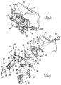
- Figures 5 and 6 show an example of a projector according to the present invention respectively, in perspective, as it is when the constituent parts are assembled, and in exploded perspective.
- FIG. 6 in this type of projector 1, are nested successively along the X axis, in the direction of projection of beams generated by this projector 1, a lamp 18, a fixed plate 10, a first part 20, a second part 22, a reflector 6 and a blackout 34.
- the reflector 6 has three legs 36 on which are screwed three screws 30 to maintain the second part 22 rigidly connected to the reflector 6.
- the second part 22 has three ears 40. Each of these ears 40 are pierced with two holes 41, 42. One, the hole 41, makes it possible to pass a screw 38 for fixing the second part 22 to the reflector 6.
- the other, hole 42 keeps the reflector 6 on the fixed plate 10 thanks to threaded rods 43 and springs 44.
- the threaded rods 43 and the springs 44 allow movement, both along the X axis and in a plane perpendicular to the X axis, of the reflector 6 relative to the fixed plate 10, between two positions corresponding to the PC code and road positions respectively PR.
- the springs 44 serve to recall the headlamp from the road position PR to position PC code.
- the fixed plate 10 comprises a cylindrical projecting element 45 of revolution around passage 19, extending in the direction of projection beams generated by the projector 1.
- the first part 20 is threaded on this projecting element 45. The latter allows guidance of the rotation of the first part 20 around the X axis.
- the first 20 and second 22 pieces each have three ramps. Each ramp of each first 20 or second 22 piece is able to cooperate with a ramp from the other part 20 or 22.
- Each ramp rises from the washer constituting each first 20 or second 22 piece, towards a flat 51, when turning in the clockwise, around the X axis, facing the surface of this washer which has the ramps.
- the surface of flat 51 is perpendicular to the X axis.
- the micromotor 33 is fixed on a support 35, itself fixed on the fixed plate 10.
- This support 35 and the fixed plate 10 include a cutout in which the toothed wheel 30 has passed in order to cooperate with the toothed sector 29, as shown in FIG. 7.
- the micromotor 33 is powered and controlled by the voltages available, on the vehicle code and route harnesses automotive, without any modification of wiring used for a projector conventional.
- the lamp 18 is held on the fixed plate thanks to a clip 46, itself fixed on this fixed plate 10 by tabs 47.
- the lamp 18 is connected to the motor vehicle electrical supply circuit thanks to a connector 48.
- the projector is mounted on the chassis of the motor vehicle thanks to fixing lugs 50 screwed onto the fixed plate 10.
- first 24 and second 26 ramps can be replaced by threaded elements cooperating with each other.
- the threads have sufficient play between them to allow movement in a plane perpendicular to the axis of screwing and unscrewing the threads one inside the other.
- a variant of the projector according to the invention has been described above. allowing, with a single light source, to produce a beam of road or a passing beam. But according to other variants, the projector allows, with a single light source, to produce a beam anti-fog or high beam or long range.
Landscapes
- Engineering & Computer Science (AREA)
- Mechanical Engineering (AREA)
- General Engineering & Computer Science (AREA)
- Non-Portable Lighting Devices Or Systems Thereof (AREA)
- Lighting Device Outwards From Vehicle And Optical Signal (AREA)
Abstract
Description
- la figure 1 est une représentation schématique en coupe médiane selon un plan vertical parallèle à la direction d'éclairage, d'un projecteur conforme à la présente invention ;
- la figure 2 est une représentation schématique en coupe médiane selon un plan vertical parallèle à la direction d'éclairage, d'un exemple de mécanisme de déplacement du miroir du projecteur représenté sur la figure 1, celui-ci étant dans une première configuration ;
- la figure 3 est une représentation analogue à celle de la figure 2, le mécanisme de déplacement du miroir étant dans une deuxième configuration ;
- la figure 4 est une représentation schématique de pièces du mécanisme représenté sur les figures 2 et 3, vu parallèlement à la direction d'éclairage ;
- la figure 5 est une vue en perspective d'un exemple de projecteur conforme à l'invention ;
- la figure 6 est une vue en perspective éclatée du projecteur représenté sur la figure 5 ; et
- la figure 7 représente en semi-transparence et en coupe perpendiculairement à la direction d'éclairage, une platine et un micromoteur équipant le projecteur représenté aux figures 5 et 6.
- d'une part en effectuant une translation, suivant un premier mouvement de translation, de l'ordre de 2 mm du réflecteur 6 par rapport à la platine fixe 10 selon l'axe de projection X, et
- d'autre part une translation verticale, suivant un deuxième mouvement de translation, de 1 mm environ vers le haut, selon un axe Y.
Claims (10)
- Projecteur de véhicule muni d'une came (12) pour déplacer un réflecteur (6) et une source lumineuse (8) l'un par rapport à l'autre, pour engendrer deux faisceaux lumineux différents, cette came (12) comportant une première (20) et une deuxième (22) pièces et transformant un mouvement de rotation de la première pièce (20) autour d'un axe de rotation (X), en un premier mouvement de translation de la deuxième pièce (22), caractérisé par le fait que le premier mouvement de translation est réalisé colinéairement à l'axe de rotation (X).
- Projecteur selon la revendication 1, caractérisé par le fait que les première (20) et deuxième (22) pièces sont aptes à un deuxième mouvement de translation, l'une par rapport à l'autre, dans un plan perpendiculaire à l'axe de rotation (X).
- Projecteur selon l'une des revendications précédentes, caractérisé par le fait que la première pièce (20), au cours de sa rotation par rapport à la deuxième pièce (22), est apte à pousser la deuxième pièce (22) parallèlement à l'axe de rotation (X).
- Projecteur selon l'une des revendications précédentes, caractérisé par le fait qu'au moins l'une des première (20) et deuxième (22) pièces est munie d'une rampe (24, 26) présentant une surface s'écartant d'un plan perpendiculaire à l'axe de rotation (X), selon une trajectoire décrivant un arc de cercle autour de cet axe (X).
- Projecteur selon l'une des revendications précédentes, caractérisé par le fait que les première (20) et deuxième (22) pièces comportent un passage pour une lampe (18) ou un support de lampe (16).
- Projecteur selon l'une des revendications précédentes, caractérisé par le fait que, lorsque le projecteur (1) est monté sur le véhicule, le premier mouvement de translation s'effectue selon un axe horizontal (X).
- Projecteur selon l'une des revendications 2 à 7, caractérisé par le fait que, lorsque le projecteur (1) est monté sur le véhicule, le deuxième mouvement de translation s'effectue selon un axe vertical (Y).
- Projecteur selon l'une des revendications précédentes caractérisé par le fait que le déplacement du réflecteur (6) et de la source lumineuse (8) l'un par rapport à l'autre permet un passage d'un éclairage par le projecteur (1) avec un faisceau de route à un éclairage par le projecteur (1 ) avec un faisceau de croisement ou inversement.
- Projecteur selon l'une des revendications précédentes, caractérisé par le fait que l'une des première (20) et deuxième (22) pièces est munie d'un secteur denté (29) pour être entraínée en rotation autour de l'axe de rotation (X), par un micromoteur (33).
- Projecteur selon la revendication 9, caractérisé par le fait que le micromoteur (33) alimenté et commandé par les tensions disponibles sur les faisceaux électriques pour les éclairages de croisement et de route du véhicule.
Applications Claiming Priority (2)
| Application Number | Priority Date | Filing Date | Title |
|---|---|---|---|
| FR9902161A FR2790062B1 (fr) | 1999-02-22 | 1999-02-22 | Projecteur de vehicule capable d'emettre deux faisceaux lumineux differents avec une source unique |
| FR9902161 | 1999-02-22 |
Publications (2)
| Publication Number | Publication Date |
|---|---|
| EP1031786A1 true EP1031786A1 (fr) | 2000-08-30 |
| EP1031786B1 EP1031786B1 (fr) | 2007-03-28 |
Family
ID=9542351
Family Applications (1)
| Application Number | Title | Priority Date | Filing Date |
|---|---|---|---|
| EP00400123A Expired - Lifetime EP1031786B1 (fr) | 1999-02-22 | 2000-01-18 | Projecteur de véhicule capable d'émettre deux faisceaux lumineux différents avec une source unique |
Country Status (6)
| Country | Link |
|---|---|
| US (1) | US6354722B1 (fr) |
| EP (1) | EP1031786B1 (fr) |
| JP (1) | JP4511671B2 (fr) |
| DE (1) | DE60034085T2 (fr) |
| ES (1) | ES2283278T3 (fr) |
| FR (1) | FR2790062B1 (fr) |
Cited By (3)
| Publication number | Priority date | Publication date | Assignee | Title |
|---|---|---|---|---|
| DE10247383A1 (de) * | 2002-10-10 | 2004-04-22 | Hella Kg Hueck & Co. | Scheinwerfer für Fahrzeuge |
| CN102139658A (zh) * | 2010-02-02 | 2011-08-03 | 法雷奥照明公司 | 用于机动车辆照明和/或信号装置的元件移位的装置以及用于应用这种类型装置的方法 |
| WO2013055672A1 (fr) * | 2011-10-11 | 2013-04-18 | Sabic Innovative Plastics Ip B.V. | Structure de montage pour réflecteur de phare |
Families Citing this family (9)
| Publication number | Priority date | Publication date | Assignee | Title |
|---|---|---|---|---|
| JP2001057104A (ja) * | 1999-08-18 | 2001-02-27 | Ichikoh Ind Ltd | 自動車用ヘッドランプ |
| US6513952B1 (en) * | 2001-11-06 | 2003-02-04 | General Electric Company | Socket mounting that allows lamp to remain vertical as fixture is tilted |
| GB0408102D0 (en) | 2004-04-08 | 2004-05-12 | Autoflame Eng Ltd | Total dissolved solids |
| US7682038B2 (en) * | 2005-08-16 | 2010-03-23 | The Brinkman Corporation | Portable light having multi-mode reflector |
| JP4714088B2 (ja) * | 2006-06-16 | 2011-06-29 | 株式会社小糸製作所 | 車両用前照灯 |
| US7810972B2 (en) * | 2006-10-13 | 2010-10-12 | Visteon Global Technologies, Inc. | Headlamp assembly having an adjustable light beam direction |
| JP2012519934A (ja) * | 2009-03-06 | 2012-08-30 | コーニンクレッカ フィリップス エレクトロニクス エヌ ヴィ | ピーク/フラット調節 |
| JP2015032567A (ja) * | 2013-08-07 | 2015-02-16 | パナソニック株式会社 | 照明器具 |
| CN114413229B (zh) * | 2021-12-31 | 2025-07-18 | 山东鲁得贝车灯股份有限公司 | 一种车灯调光装置、调光方法及车灯 |
Citations (4)
| Publication number | Priority date | Publication date | Assignee | Title |
|---|---|---|---|---|
| FR2276195A1 (fr) * | 1974-06-28 | 1976-01-23 | Sev Marchal | Dispositif pour le reglage manuel predetermine de l'orientation des projecteurs d'eclairage d'un vehicule automobile |
| FR2432405A1 (fr) * | 1978-08-03 | 1980-02-29 | Mes Sa | Dispositif destine a modifier le calage des phares d'un vehicule automobile en fonction de la charge transportee |
| EP0791780A1 (fr) * | 1996-02-20 | 1997-08-27 | Valeo Vision | Projecteur de vehicule automobile, comportant une source lumineuse unique et susceptible d'emettre un faisceau de croisement et un faisceau de route |
| FR2765308A1 (fr) | 1997-06-30 | 1998-12-31 | Valeo Vision | Projecteur de vehicule automobile capable d'emettre, avec une source lumineuse unique, deux faisceaux differents |
Family Cites Families (13)
| Publication number | Priority date | Publication date | Assignee | Title |
|---|---|---|---|---|
| US1083530A (en) * | 1913-01-06 | 1914-01-06 | Jean Gallay | Electric search-lamp for automobiles. |
| US1512158A (en) * | 1924-02-26 | 1924-10-21 | Bragg Thomas Milton | Automobile headlamp |
| US1674650A (en) * | 1926-11-19 | 1928-06-26 | Bright Star Battery Company | Portable electric light |
| US5806964A (en) * | 1984-09-06 | 1998-09-15 | Mag Instrument, Inc. | Miniature flashlight |
| JPH0326454Y2 (fr) * | 1985-03-29 | 1991-06-07 | ||
| JPH0318280Y2 (fr) * | 1986-09-19 | 1991-04-17 | ||
| JPH0725504U (ja) * | 1993-10-15 | 1995-05-12 | 株式会社小糸製作所 | ヘッドランプの光軸調整装置 |
| JPH1092208A (ja) * | 1996-09-20 | 1998-04-10 | Stanley Electric Co Ltd | 車両用前照灯 |
| JP2965930B2 (ja) * | 1997-03-07 | 1999-10-18 | スタンレー電気株式会社 | 車両用前照灯 |
| DE19710632A1 (de) * | 1997-03-14 | 1998-09-17 | Bosch Gmbh Robert | Scheinwerfer für Abblendlicht und Fernlicht für Fahrzeuge |
| US6004008A (en) * | 1998-03-26 | 1999-12-21 | Plum Industrial Co., Ltd. | Multi-functional flashlight |
| JP2000090721A (ja) * | 1998-09-17 | 2000-03-31 | Koito Mfg Co Ltd | 車両用前照灯 |
| US6174071B1 (en) * | 1999-04-28 | 2001-01-16 | Kwong Chi Chan | Flashlight |
-
1999
- 1999-02-22 FR FR9902161A patent/FR2790062B1/fr not_active Expired - Fee Related
-
2000
- 2000-01-18 ES ES00400123T patent/ES2283278T3/es not_active Expired - Lifetime
- 2000-01-18 DE DE60034085T patent/DE60034085T2/de not_active Expired - Lifetime
- 2000-01-18 EP EP00400123A patent/EP1031786B1/fr not_active Expired - Lifetime
- 2000-02-22 JP JP2000043844A patent/JP4511671B2/ja not_active Expired - Fee Related
- 2000-02-22 US US09/510,447 patent/US6354722B1/en not_active Expired - Lifetime
Patent Citations (4)
| Publication number | Priority date | Publication date | Assignee | Title |
|---|---|---|---|---|
| FR2276195A1 (fr) * | 1974-06-28 | 1976-01-23 | Sev Marchal | Dispositif pour le reglage manuel predetermine de l'orientation des projecteurs d'eclairage d'un vehicule automobile |
| FR2432405A1 (fr) * | 1978-08-03 | 1980-02-29 | Mes Sa | Dispositif destine a modifier le calage des phares d'un vehicule automobile en fonction de la charge transportee |
| EP0791780A1 (fr) * | 1996-02-20 | 1997-08-27 | Valeo Vision | Projecteur de vehicule automobile, comportant une source lumineuse unique et susceptible d'emettre un faisceau de croisement et un faisceau de route |
| FR2765308A1 (fr) | 1997-06-30 | 1998-12-31 | Valeo Vision | Projecteur de vehicule automobile capable d'emettre, avec une source lumineuse unique, deux faisceaux differents |
Cited By (7)
| Publication number | Priority date | Publication date | Assignee | Title |
|---|---|---|---|---|
| DE10247383A1 (de) * | 2002-10-10 | 2004-04-22 | Hella Kg Hueck & Co. | Scheinwerfer für Fahrzeuge |
| CN102139658A (zh) * | 2010-02-02 | 2011-08-03 | 法雷奥照明公司 | 用于机动车辆照明和/或信号装置的元件移位的装置以及用于应用这种类型装置的方法 |
| CN102139658B (zh) * | 2010-02-02 | 2016-01-06 | 法雷奥照明公司 | 用于机动车辆照明和/或信号装置的元件移位的装置以及用于应用这种类型装置的方法 |
| WO2013055672A1 (fr) * | 2011-10-11 | 2013-04-18 | Sabic Innovative Plastics Ip B.V. | Structure de montage pour réflecteur de phare |
| CN103889780A (zh) * | 2011-10-11 | 2014-06-25 | 沙特基础创新塑料Ip私人有限责任公司 | 前照灯反射器的安装结构 |
| US9151459B2 (en) | 2011-10-11 | 2015-10-06 | Sabic Global Technologies B.V. | Mounting structure for a headlamp reflector |
| CN103889780B (zh) * | 2011-10-11 | 2016-11-09 | 沙特基础全球技术有限公司 | 安装支架及包括该安装支架的前照灯总成 |
Also Published As
| Publication number | Publication date |
|---|---|
| JP2000243107A (ja) | 2000-09-08 |
| ES2283278T3 (es) | 2007-11-01 |
| DE60034085D1 (de) | 2007-05-10 |
| US6354722B1 (en) | 2002-03-12 |
| FR2790062B1 (fr) | 2001-06-08 |
| DE60034085T2 (de) | 2007-12-27 |
| JP4511671B2 (ja) | 2010-07-28 |
| EP1031786B1 (fr) | 2007-03-28 |
| FR2790062A1 (fr) | 2000-08-25 |
Similar Documents
| Publication | Publication Date | Title |
|---|---|---|
| FR2906771A1 (fr) | Lampe pour vehicule | |
| EP1031786B1 (fr) | Projecteur de véhicule capable d'émettre deux faisceaux lumineux différents avec une source unique | |
| FR2809358A1 (fr) | Phare de vehicule ayant deux unites a lampe | |
| JP2000280946A5 (fr) | ||
| EP1308669A1 (fr) | Dispositif d'éclairage de type elliptique pour véhicule automobile | |
| FR2760069A1 (fr) | Systeme d'eclairage a projecteurs de faisceau proche de type code et de faisceau complementaire de virage | |
| EP2574503A1 (fr) | Module de projecteur de véhicule avec fixation a baionnette, support et projecteur correspondant | |
| FR2804918A1 (fr) | Phare pour vehicule | |
| FR2813051A1 (fr) | Projecteur de vehicule pour generer les feux de croisement et au moins un faisceau lumineux de plus grande portee | |
| EP0380396A1 (fr) | Projecteur de véhicule automobile comportant une source lumineuse unique et engendrant deux faisceaux différents | |
| EP0791780B1 (fr) | Projecteur de vehicule automobile, comportant une source lumineuse unique et susceptible d'emettre un faisceau de croisement et un faisceau de route | |
| FR2819764A1 (fr) | Phare de vehicule a deux reflecteurs | |
| EP1422471A2 (fr) | Projecteur elliptique pour véhicule automobile émettant des faisceaux d'éclairage différents | |
| EP1739346B1 (fr) | Dispositif projecteur antibrouillard avec lentille de projection | |
| FR2631294A1 (fr) | Dispositif d'inclinaison des phares pour vehicules | |
| FR2943760A1 (fr) | Module de lampe pour un dispositif d'eclairage d'un vehicule automobile et dispositif d'eclairage avec un tel module de lampe | |
| EP0889281B1 (fr) | Projecteur de véhicule automobile capable d'émettre, avec une source lumineuse unique, deux faisceaux différents | |
| EP1231107A1 (fr) | Bloc optique de véhicule comportant des moyens de fixation de projecteurs améliorés | |
| FR2802869A1 (fr) | Dispositif d'eclairage notamment pour un habitacle de vehicule automobile et plafonnier comportant un tel dispositif d'eclairage | |
| FR2895782A1 (fr) | Dispositif projecteur elliptique multifonctions avec element optique additionnel | |
| FR2601111A1 (fr) | Projecteur de vehicule automobile, a deux miroirs reglables mutuellement | |
| EP1621810A1 (fr) | Module optique elliptique à occulteur pour véhicule automobile | |
| JP3128605B2 (ja) | 前照灯の照射軸調整装置 | |
| JPH04129850A (ja) | 二輪車用前照灯装置のレベリング装置 | |
| FR2631904A1 (fr) | Dispositif de reglage de la direction du faisceau d'un phare pour vehicules |
Legal Events
| Date | Code | Title | Description |
|---|---|---|---|
| PUAI | Public reference made under article 153(3) epc to a published international application that has entered the european phase |
Free format text: ORIGINAL CODE: 0009012 |
|
| 17P | Request for examination filed |
Effective date: 20000526 |
|
| AK | Designated contracting states |
Kind code of ref document: A1 Designated state(s): DE ES GB IT |
|
| AX | Request for extension of the european patent |
Free format text: AL;LT;LV;MK;RO;SI |
|
| AKX | Designation fees paid |
Free format text: DE ES GB IT |
|
| RIC1 | Information provided on ipc code assigned before grant |
Ipc: F21V 14/04 20060101AFI20060922BHEP Ipc: F21W 101/10 20060101ALI20060922BHEP Ipc: B60Q 1/068 20060101ALI20060922BHEP |
|
| GRAP | Despatch of communication of intention to grant a patent |
Free format text: ORIGINAL CODE: EPIDOSNIGR1 |
|
| GRAS | Grant fee paid |
Free format text: ORIGINAL CODE: EPIDOSNIGR3 |
|
| GRAA | (expected) grant |
Free format text: ORIGINAL CODE: 0009210 |
|
| AK | Designated contracting states |
Kind code of ref document: B1 Designated state(s): DE ES GB IT |
|
| REG | Reference to a national code |
Ref country code: GB Ref legal event code: FG4D Free format text: NOT ENGLISH |
|
| REF | Corresponds to: |
Ref document number: 60034085 Country of ref document: DE Date of ref document: 20070510 Kind code of ref document: P |
|
| GBV | Gb: ep patent (uk) treated as always having been void in accordance with gb section 77(7)/1977 [no translation filed] |
Effective date: 20070328 |
|
| REG | Reference to a national code |
Ref country code: ES Ref legal event code: FG2A Ref document number: 2283278 Country of ref document: ES Kind code of ref document: T3 |
|
| PLBE | No opposition filed within time limit |
Free format text: ORIGINAL CODE: 0009261 |
|
| STAA | Information on the status of an ep patent application or granted ep patent |
Free format text: STATUS: NO OPPOSITION FILED WITHIN TIME LIMIT |
|
| 26N | No opposition filed |
Effective date: 20080102 |
|
| PG25 | Lapsed in a contracting state [announced via postgrant information from national office to epo] |
Ref country code: GB Free format text: LAPSE BECAUSE OF FAILURE TO SUBMIT A TRANSLATION OF THE DESCRIPTION OR TO PAY THE FEE WITHIN THE PRESCRIBED TIME-LIMIT Effective date: 20070328 |
|
| PGFP | Annual fee paid to national office [announced via postgrant information from national office to epo] |
Ref country code: IT Payment date: 20080124 Year of fee payment: 9 |
|
| PG25 | Lapsed in a contracting state [announced via postgrant information from national office to epo] |
Ref country code: IT Free format text: LAPSE BECAUSE OF NON-PAYMENT OF DUE FEES Effective date: 20090118 |
|
| PGFP | Annual fee paid to national office [announced via postgrant information from national office to epo] |
Ref country code: DE Payment date: 20170117 Year of fee payment: 18 |
|
| PGFP | Annual fee paid to national office [announced via postgrant information from national office to epo] |
Ref country code: ES Payment date: 20170131 Year of fee payment: 18 |
|
| REG | Reference to a national code |
Ref country code: DE Ref legal event code: R119 Ref document number: 60034085 Country of ref document: DE |
|
| PG25 | Lapsed in a contracting state [announced via postgrant information from national office to epo] |
Ref country code: DE Free format text: LAPSE BECAUSE OF NON-PAYMENT OF DUE FEES Effective date: 20180801 |
|
| REG | Reference to a national code |
Ref country code: ES Ref legal event code: FD2A Effective date: 20190730 |
|
| PG25 | Lapsed in a contracting state [announced via postgrant information from national office to epo] |
Ref country code: ES Free format text: LAPSE BECAUSE OF NON-PAYMENT OF DUE FEES Effective date: 20180119 |