EP1031461A2 - Vehicle seat backrest - Google Patents
Vehicle seat backrest Download PDFInfo
- Publication number
- EP1031461A2 EP1031461A2 EP99125779A EP99125779A EP1031461A2 EP 1031461 A2 EP1031461 A2 EP 1031461A2 EP 99125779 A EP99125779 A EP 99125779A EP 99125779 A EP99125779 A EP 99125779A EP 1031461 A2 EP1031461 A2 EP 1031461A2
- Authority
- EP
- European Patent Office
- Prior art keywords
- backrest
- frame
- tubular frame
- vehicle seat
- plastic carrier
- Prior art date
- Legal status (The legal status is an assumption and is not a legal conclusion. Google has not performed a legal analysis and makes no representation as to the accuracy of the status listed.)
- Granted
Links
- 229920003023 plastic Polymers 0.000 claims abstract description 17
- 239000004033 plastic Substances 0.000 claims abstract description 17
- 239000011120 plywood Substances 0.000 abstract 1
- 210000002414 leg Anatomy 0.000 description 10
- 230000005489 elastic deformation Effects 0.000 description 6
- 239000006260 foam Substances 0.000 description 2
- 238000010521 absorption reaction Methods 0.000 description 1
- 230000001133 acceleration Effects 0.000 description 1
- 238000005452 bending Methods 0.000 description 1
- 238000010276 construction Methods 0.000 description 1
- 238000011161 development Methods 0.000 description 1
- 230000018109 developmental process Effects 0.000 description 1
- 210000003127 knee Anatomy 0.000 description 1
- 239000000463 material Substances 0.000 description 1
Images


Classifications
-
- B—PERFORMING OPERATIONS; TRANSPORTING
- B60—VEHICLES IN GENERAL
- B60N—SEATS SPECIALLY ADAPTED FOR VEHICLES; VEHICLE PASSENGER ACCOMMODATION NOT OTHERWISE PROVIDED FOR
- B60N2/00—Seats specially adapted for vehicles; Arrangement or mounting of seats in vehicles
- B60N2/24—Seats specially adapted for vehicles; Arrangement or mounting of seats in vehicles for particular purposes or particular vehicles
- B60N2/242—Bus seats
-
- B—PERFORMING OPERATIONS; TRANSPORTING
- B60—VEHICLES IN GENERAL
- B60N—SEATS SPECIALLY ADAPTED FOR VEHICLES; VEHICLE PASSENGER ACCOMMODATION NOT OTHERWISE PROVIDED FOR
- B60N2/00—Seats specially adapted for vehicles; Arrangement or mounting of seats in vehicles
- B60N2/68—Seat frames
- B60N2/686—Panel like structures
-
- B—PERFORMING OPERATIONS; TRANSPORTING
- B60—VEHICLES IN GENERAL
- B60N—SEATS SPECIALLY ADAPTED FOR VEHICLES; VEHICLE PASSENGER ACCOMMODATION NOT OTHERWISE PROVIDED FOR
- B60N2/00—Seats specially adapted for vehicles; Arrangement or mounting of seats in vehicles
- B60N2/80—Head-rests
- B60N2/803—Head-rests fixed
-
- B—PERFORMING OPERATIONS; TRANSPORTING
- B60—VEHICLES IN GENERAL
- B60N—SEATS SPECIALLY ADAPTED FOR VEHICLES; VEHICLE PASSENGER ACCOMMODATION NOT OTHERWISE PROVIDED FOR
- B60N2/00—Seats specially adapted for vehicles; Arrangement or mounting of seats in vehicles
- B60N2/80—Head-rests
- B60N2/888—Head-rests with arrangements for protecting against abnormal g-forces, e.g. by displacement of the head-rest
Definitions
- the invention relates to a backrest for one Vehicle seat, in particular for a passenger chair Omnibuses, which in the preamble of claim 1 specified genus.
- the seat frame made up of a seat frame and a backrest frame, which are each formed by a circumferential pipe string.
- a seat part on the seat frame and on the backrest frame is a back part with a molded on end Clip the head support section.
- Seat and backrest part each formed by a rigid plastic shell that with a foam pad is covered.
- the invention has for its object a backrest of the type mentioned at the beginning to create the sufficient is stable, a defined in certain areas Has elasticity and when exposed to dynamic Forces absorbs deformation energy.
- the object of the invention is through the features of Claim 1 solved.
- the backrest according to the invention has the advantage that it is made of three different components, namely tubular frames, Wooden plate and plastic support, is composed and through the targeted use of materials and geometries these components have a defined strength in the desired Areas and a defined elasticity in others Areas is reached.
- the tubular frame carries when dynamic forces act on the backrest, e.g. in the event of a frontal impact of the vehicle, due to plastic Deformation to reduce energy.
- the one with the wooden plate populated tubular frame takes in the lower area of the backrest the strain on the knee force due to deformation of the tube due to a bending load.
- the legs of the U-shaped tubular frame at different Sections of their longitudinal course sawn in to different depths.
- the force is absorbed by these defined saw cuts of the tubular frame through targeted elastic deformation significantly improved.
- the legs of the U-shaped tubular frame two striving downwards, preferably with the legs aligned levers for backrest connection to a seat base welded the vehicle seat, and the levers are with at least one swiveling the backrest backwards preventing stop.
- the attack ensures sufficient stability of the tubular frame against Shift to the rear.
- the levers are also used for recording the backrest adjustment mechanism and the armrest.
- the plastic carrier is an evenly formed one Honeycomb structure.
- This chamber construction from similar Honeycomb does a great deal of elastic deformation work Influence of dynamic forces.
- This ergonomically into the Integrated backrest handles make it easier Vehicle occupants taking a seat on the behind arranged vehicle seat and getting up from this Vehicle seat by holding on to the handles.
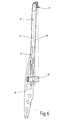
- the in Fig. 1 in longitudinal section and in Figs. 2-4 backrest shown in perspective in its individual parts of a passenger chair for a bus as Embodiment for a general vehicle seat has a tubular frame 11, a multi-layer glued wooden panel 12, an elastically deformable plastic carrier 13 and a backrest cushion 14 shaped to fit the seat.
- the tubular frame 11 is bent from one piece in a U-shape, the two Extend frame leg 111 to the lower edge of the backrest and via a cross strut 15, which is close to the free leg ends starts, are connected.
- At the free ends of the Frame legs 111 place two downward striving with the frame leg 111 aligned lever 16 to the Frame legs 111 are welded (Fig. 2 and 6).
- This Levers 16 are used to connect the backrest to the Underframe of the passenger chair and to accommodate one Backrest adjustment mechanism.
- the levers also serve 16 the inclusion of the center armrests for the passenger chair.
- the levers 16 are with one swiveling the backrest backwards preventing stop.
- the two frame legs 111 are different Make their longitudinal course different depth from the front sawn. Through these defined saw cuts 17 Force absorption of the tubular frame 11 by targeted elastic Deformation improved significantly.
Abstract
Description
Die Erfindung betrifft eine Rückenlehne für einen Fahrzeugsitz, insbesondere für einen Fahrgaststuhl eines Omnibusses, der im Oberbegriff des Patentanspruchs 1 angegebenen Gattung.The invention relates to a backrest for one Vehicle seat, in particular for a passenger chair Omnibuses, which in the preamble of claim 1 specified genus.
Bei einer bekannten Rückenlehne dieser Art (DE 37 05 542 C2) sind an den U-Schenkeln des U-förmigen Rohrrahmens quer zu den Schenkeln verlaufende Stützfedern befestigt, auf denen ein den Rohrrahmen teilweise umgreifendes Polster aus einem Schaumstoff aufliegt. Das Polster ist mit einem Polsterbezug überzogen.In a known backrest of this type (DE 37 05 542 C2) are at right angles to the U-legs of the U-shaped tubular frame attached to the legs extending support springs on which a cushion partially encompassing the tubular frame from one Foam rests. The upholstery is covered with an upholstery overdrawn.
Bei einem bekannten Fahrzeugsitz (FR 2 698 832 A1) besteht das Sitzgestell aus einem Sitzrahmen und einem Lehnenrahmen, die jeweils von einem umlaufenden Rohrstrang gebildet sind. Auf den Sitzrahmen ist ein Sitzteil und auf den Lehnenrahmen ist ein Rückenteil mit einem endseitig angeformten Kopf abstützabschnitt aufgeclipst. Sitz- und Lehnenteil werden jeweils von einer steifen Kunststoffschale gebildet, die mit einem Schaumpolster belegt ist. In a known vehicle seat (FR 2 698 832 A1) the seat frame made up of a seat frame and a backrest frame, which are each formed by a circumferential pipe string. There is a seat part on the seat frame and on the backrest frame is a back part with a molded on end Clip the head support section. Seat and backrest part each formed by a rigid plastic shell that with a foam pad is covered.
Der Erfindung liegt die Aufgabe zugrunde, eine Rückenlehne der eingangs genannten Art zu schaffen, die ausreichend stabil ist, in bestimmten Bereichen eine definierte Elastizität aufweist und bei Einwirkung von dynamischen Kräften Verformungsenergie aufnimmt.The invention has for its object a backrest of the type mentioned at the beginning to create the sufficient is stable, a defined in certain areas Has elasticity and when exposed to dynamic Forces absorbs deformation energy.
Die Aufgabe ist erfindungsgemäß durch die Merkmale des Patentanspruchs 1 gelöst. The object of the invention is through the features of Claim 1 solved.
Die erfindungsgemäße Rückenlehne hat den Vorteil, daß sie aus drei unterschiedlichen Bauteilen, nämlich Rohrrahmen, Holzplatte und Kunststoffträger, zusammengesetzt ist und durch den gezielten Einsatz von Materialien und Geometrien dieser Bauteile eine definierte Festigkeit in gewünschten Bereichen und eine definierte Elastizität in anderen Bereichen erreicht wird. Gleichzeitig trägt der Rohrrahmen bei Einwirkung von dynamischen Kräften auf die Rückenlehne, z.B. bei Frontalaufprall des Fahrzeugs, durch plastische Verformung zum Energieabbau bei. Der mit der Holzplatte bestückte Rohrrahmen nimmt im unteren Bereich der Rückenlehne die Belastung der Kniekraft durch Verformung des Rohres aufgrund einer Biegebelastung auf. Im oberen Bereich, in dem der Plattenabschnitt freitragend ist und nicht mehr durch den Rohrrahmen unterstützt ist, wird durch eine elastische Verformung der Holzplatte und des oberen Bereichs des Rohrrahmens die durch den Aufprall des Kopfes erzeugte Kraft definiert absorbiert und somit die auf den Kopf des Fahrzeuginsassens wirkende Beschleunigungskraft niedrig gehalten. Der Kunststoffträger leistet im Crashfall durch seine elastische Verformung einen zusätzlichen Beitrag zum Abbau der Beschleunigungskräfte im Kopfbereich.The backrest according to the invention has the advantage that it is made of three different components, namely tubular frames, Wooden plate and plastic support, is composed and through the targeted use of materials and geometries these components have a defined strength in the desired Areas and a defined elasticity in others Areas is reached. At the same time, the tubular frame carries when dynamic forces act on the backrest, e.g. in the event of a frontal impact of the vehicle, due to plastic Deformation to reduce energy. The one with the wooden plate populated tubular frame takes in the lower area of the backrest the strain on the knee force due to deformation of the tube due to a bending load. In the upper area, in the the plate section is unsupported and no longer by the Pipe frame is supported by an elastic Deformation of the wooden plate and the upper area of the Tubular frame the force generated by the impact of the head absorbed and thus defined on the head of the Vehicle occupant accelerating force low held. The plastic carrier performs in the event of a crash its elastic deformation makes an additional contribution to Reduction of the acceleration forces in the head area.
Vorteilhafte Ausführungsformen der erfindungsgemäßen Rückenlehne mit zweckmäßigen Ausgestaltungen und Weiterbildungen der Erfindung ergeben sich aus den weiteren Ansprüchen.Advantageous embodiments of the invention Backrest with practical designs and Further developments of the invention result from the others Claims.
Gemäß einer vorteilhaften Ausführungsform der Erfindung sind die Schenkel des U-förmigen Rohrrahmens an verschiedenen Stellen ihres Längsverlaufs unterschiedlich tief eingesägt. According to an advantageous embodiment of the invention the legs of the U-shaped tubular frame at different Sections of their longitudinal course sawn in to different depths.
Durch diese definierten Sägeschnitte wird die Kraftaufnahme des Rohrrahmens durch gezielte elastische Verformung wesentlich verbessert.The force is absorbed by these defined saw cuts of the tubular frame through targeted elastic deformation significantly improved.
Gemäß einer bevorzugten Ausführungsform der Erfindung sind an den freien Enden der Schenkel des U-förmigen Rohrrahmens zwei nach unten wegstrebende, vorzugsweise mit den Schenkeln fluchtende Hebel zur Lehnenanbindung an ein Sitzuntergestell des Fahrzeugsitzes angeschweißt, und die Hebel sind mit mindestens einem das Abschwenken der Lehne nach hinten unterbindenden Anschlag versehen. Der Anschlag sorgt für ausreichende Stabilität des Rohrrahmens gegen eine Verlagerung nach hinten. Die Hebel dienen zudem der Aufnahme des Lehnenverstellmechanismus und der Armlehne.According to a preferred embodiment of the invention are on the free ends of the legs of the U-shaped tubular frame two striving downwards, preferably with the legs aligned levers for backrest connection to a seat base welded the vehicle seat, and the levers are with at least one swiveling the backrest backwards preventing stop. The attack ensures sufficient stability of the tubular frame against Shift to the rear. The levers are also used for recording the backrest adjustment mechanism and the armrest.
Gemäß einer vorteilhaften Ausführungsform der Erfindung weist der Kunststoffträger eine gleichmäßig ausgebildete Wabenstruktur auf. Diese Kammerstruktion aus gleichartigen Waben leistet in hohem Maße elastische Verformungsarbeit bei Einwirkung von dynamischen Kräften.According to an advantageous embodiment of the invention the plastic carrier is an evenly formed one Honeycomb structure. This chamber construction from similar Honeycomb does a great deal of elastic deformation work Influence of dynamic forces.
Gemäß einer vorteilhaften Ausführungsform der Erfindung sind an dem Kunststoffträger zwei Haltegriffe mit Querabstand voneinander angeordnet, wobei die Haltegriffe vorzugsweise in die Lehnenkontur einbezogen sind. Diese ergonomisch in die Rückenlehne integrierten Griffe erleichtern den Fahrzeuginsassen das Platznehmen auf dem dahinter angeordneten Fahrzeugsitz und das Aufstehen von diesem Fahrzeugsitz durch Festhalten an den Griffen. According to an advantageous embodiment of the invention two handles with transverse spacing on the plastic carrier arranged from each other, the handles preferably in the backrest contour is included. This ergonomically into the Integrated backrest handles make it easier Vehicle occupants taking a seat on the behind arranged vehicle seat and getting up from this Vehicle seat by holding on to the handles.
Die Erfindung ist anhand eines in der Zeichnung dargestellten Ausführungsbeispiels im folgenden näher beschrieben. Es zeigen:
- Fig. 1
- einen Längsschnitt einer Rückenlehne eines Fahrgaststuhls für einen Omnibus,
- Fig. 2
- eine perspektivische Ansicht eines Rohrrahmens in der Rückenlehne gemäß Fig. 1,
- Fig. 3
- eine perspektivische Ansicht einer am Rohrrahmen befestigten Holzplatte,
- Fig. 4
- eine perspektivische Ansicht eines zur Befestigung auf der Holzplatte vorgesehenen Kunststoffträgers,
- Fig. 5
- ausschnittweise eine Vorderansicht der Rückenlehne in Fig. 1,
- Fig. 6
- eine Seitenansicht des Rohrrahmens in Richtung Pfeil VI in Fig. 2.
- Fig. 1
- 2 shows a longitudinal section of a backrest of a passenger chair for a bus,
- Fig. 2
- 2 shows a perspective view of a tubular frame in the backrest according to FIG. 1,
- Fig. 3
- a perspective view of a wooden plate attached to the tubular frame,
- Fig. 4
- 1 shows a perspective view of a plastic carrier provided for fastening on the wooden plate,
- Fig. 5
- excerpts a front view of the backrest in Fig. 1,
- Fig. 6
- a side view of the tubular frame in the direction of arrow VI in Fig. 2nd
Die in Fig. 1 im Längsschnitt und in Fig. 2 - 4
perspektivisch in ihren Einzelteilen dargestellte Rückenlehne
eines Fahrgaststuhls für einen Omnibus als
Ausführungsbeispiel für einen allgemeinen Fahrzeugsitz weist
einen Rohrrahmen 11, eine mehrlagig verleimte Holzplatte 12,
einen elastisch verformbaren Kunststoffträger 13 sowie ein
sitzgerecht geformtes Lehnenpolster 14 auf. Der Rohrrahmen 11
ist aus einem Stück U-förmig gebogen, wobei sich die beiden
Rahmenschenkel 111 bis zur Lehnenunterkante erstrecken und
über eine Querstrebe 15, die nahe den freien Schenkelenden
ansetzt, miteinander verbunden sind. An den freien Enden der
Rahmenschenkeln 111 setzen zwei nach unten wegstrebende, mit
den Rahmenschenkel 111 fluchtende Hebel 16 an, die an den
Rahmenschenkeln 111 angeschweißt sind (Fig. 2 und 6). Diese
Hebel 16 dienen zur Anbindung der Rückenlehne an das
Untergestell des Fahrgaststuhls und zur Aufnahme eines
Rückenlehnenverstellmechanismus. Weiterhin dienen die Hebel
16 der Aufnahme der Mittelarmlehnen für den Fahrgaststuhl.
Wie hier nicht weiter dargestellt ist, sind die Hebel 16 mit
einem das Abschwenken der Rückenlehne nach hinten
unterbindenden Anschlag versehen. Wie aus Fig. 6 ersichtlich
ist, sind die beiden Rahmenschenkel 111 an verschiedenen
Stellen ihres Längsverlaufs von vorn her unterschiedlich tief
eingesägt. Durch diese definierten Sägeschnitte 17 wird die
Kraftaufnahme des Rohrrahmens 11 durch gezielte elastische
Verformung wesentlich verbessert.The in Fig. 1 in longitudinal section and in Figs. 2-4
backrest shown in perspective in its individual parts
of a passenger chair for a bus as
Embodiment for a general vehicle seat has
a
Die in Fig.1 und 3 zu sehende Holzplatte 12 ist an dem
Rohrrahmen 11 verschraubt und weist einen nach oben über den
Rohrrahmen überstehenden freitragenden Plattenabschnitt 121
auf. Auf diesem mit der Holzplatte 12 einstückigen,
freitragenden Plattenabschnitt 121 ist der Kunststoffträger
13 (Fig. 1 und 4) aufgeschraubt. Wie aus Fig. 4 und 5
ersichtlich ist, besitzt der Kunststoffträger 13 eine
gleichmäßig ausgebildete Wabenstruktur, die sowohl den
Kunststoffträger 13 selbst als auch den darunterliegenden
Plattenabschnitt 121 absolut torsionssteif macht und in einem
hohen Maße elastische Verformungsarbeit leistet. Wie in
Fig. 5 nur für die linke Hälfte der Rückenlehne dargestellt
ist, ist links und rechts am äußeren Rand des
Kunststoffträgers 13 ein Haltegriff 18 eingeschraubt, der so
ausgebildet ist, daß er ergonomisch in die Rückenlehne
integriert ist und sich in die Kontur der Rückenlehne
einfügt. Diese Griffe 18 erleichtern das Platznehmen und das
Aufstehen eines Fahrgastes, der auf einen hinter der
Rückenlehne angeordneten Fahrgaststuhl sitzt. Die durch die
Wabenstruktur gegebene Torsionssteifheit des
Kunststoffträgers 13 und des mit diesem verbundenen
Plattenabschnitts 121 gewährleistet, daß keine Verwindung der
gesamten Rückenlehne bei einseitiger Belastung an einem
Haltegriff 18 auftritt.The seen in Fig.1 and 3
Claims (7)
dadurch gekennzeichnet,
daß auf dem Rohrrahmen (11) eine vorzugsweise mehrlagig verleimte Holzplatte (12) befestigt ist, die mit einem einstückigen, freitragenden Plattenabschnitt (121) nach oben über den Rohrrahmen (11) übersteht, und daß auf dem freitragenden Plattenabschnitt (121) ein der Kopfabstützung dienender, elastisch verformbarer Kunststoffträger (13) befestigt ist.Backrest for a vehicle seat, in particular for a passenger chair of an omnibus, with a one-piece bent U-shaped tubular frame (11), the two frame legs (111) of which extend to the lower edge of the backrest and via a cross strut (15) which attaches near the free leg ends are firmly connected
characterized,
that on the tubular frame (11) a preferably multi-layer glued wooden plate (12) is attached, which projects with an integral, self-supporting plate section (121) upwards over the tubular frame (11), and that on the self-supporting plate section (121) one of the head supports serving, elastically deformable plastic carrier (13) is attached.
dadurch gekennzeichnet,
daß die Rahmenschenkel (111) des Rohrrahmens (11) an verschiedenen Stellen ihres Längsverlaufs unterschiedlich tief eingesägt sind. Backrest according to claim 1,
characterized,
that the frame legs (111) of the tubular frame (11) are sawn in to different depths at different points along their longitudinal course.
dadurch gekennzeichnet,
daß an den freien Enden der Rahmenschenkel (111) des Rahmens (11) zwei nach unten wegstrebende, vorzugsweise mit den Rahmenschenkeln (111) fluchtende Hebel (16) zur Lehnenanbindung an ein Sitzuntergestell des Fahrzeugsitzes angeschweißt sind.Backrest according to claim 1 or 2,
characterized,
that at the free ends of the frame legs (111) of the frame (11) two downwardly striving, preferably flush with the frame legs (111) levers (16) for backrest connection to a seat base of the vehicle seat are welded.
dadurch gekennzeichnet,
daß die Hebel (16) mit mindestens einem das Abschwenken der Lehne nach hinten unterbindenden Anschlag versehen sind.Backrest according to claim 3,
characterized,
that the levers (16) are provided with at least one stop which prevents the backrest from pivoting backwards.
dadurch gekennzeichnet,
daß der Kunststoffträger (13) eine gleichmäßig ausgebildete Wabenstruktur aufweist.Backrest according to one of claims 1-4,
characterized,
that the plastic carrier (13) has a uniformly formed honeycomb structure.
dadurch gekennzeichnet,
daß an dem Kunststoffträger (13) zwei Haltegriffe (18) mit Querabstand voneinander befestigt sind.Backrest according to claim 5,
characterized,
that two handles (18) are attached to the plastic carrier (13) at a transverse distance from each other.
dadurch gekennzeichnet,
daß die Haltegriffe (18) in die Lehnenkontur einbezogen sind.Backrest according to claim 6,
characterized,
that the handles (18) are included in the backrest contour.
Applications Claiming Priority (2)
| Application Number | Priority Date | Filing Date | Title |
|---|---|---|---|
| DE19907670 | 1999-02-23 | ||
| DE19907670A DE19907670C1 (en) | 1999-02-23 | 1999-02-23 | Bus passenger seat has a tubular frame to form the backrest with a fitted plywood board extending over the frame to carry an elastic head support in a plastics honeycomb structure to cushion the head on a collision |
Publications (3)
| Publication Number | Publication Date |
|---|---|
| EP1031461A2 true EP1031461A2 (en) | 2000-08-30 |
| EP1031461A3 EP1031461A3 (en) | 2001-01-31 |
| EP1031461B1 EP1031461B1 (en) | 2002-09-11 |
Family
ID=7898500
Family Applications (1)
| Application Number | Title | Priority Date | Filing Date |
|---|---|---|---|
| EP99125779A Expired - Lifetime EP1031461B1 (en) | 1999-02-23 | 1999-12-23 | Vehicle seat backrest |
Country Status (3)
| Country | Link |
|---|---|
| EP (1) | EP1031461B1 (en) |
| AT (1) | ATE223820T1 (en) |
| DE (1) | DE19907670C1 (en) |
Cited By (6)
| Publication number | Priority date | Publication date | Assignee | Title |
|---|---|---|---|---|
| WO2006134415A1 (en) * | 2005-06-17 | 2006-12-21 | Productos Microcelulares De Colombia S.A. Promicolda | Improved seat frame having an improved structure |
| CN102442372A (en) * | 2011-10-24 | 2012-05-09 | 立兆股份有限公司 | Improved seat cushion of bicycle |
| CN103358949A (en) * | 2013-07-24 | 2013-10-23 | 苏州市润凯汽车配件制造有限公司 | Seat cushion for automobile |
| CN107234995A (en) * | 2017-06-02 | 2017-10-10 | 重庆延锋安道拓汽车部件系统有限公司 | A kind of modular motor vehicle seat back |
| GB2550342A (en) * | 2016-05-12 | 2017-11-22 | Gordon Murray Design Ltd | Vehicle seat back |
| CN108372810A (en) * | 2018-02-08 | 2018-08-07 | 重庆博奥镁铝金属制造有限公司 | A kind of bus seat skeleton |
Families Citing this family (3)
| Publication number | Priority date | Publication date | Assignee | Title |
|---|---|---|---|---|
| DE10204272A1 (en) * | 2002-02-02 | 2003-08-21 | Daimler Chrysler Ag | vehicle seat |
| EP2661985A1 (en) * | 2012-05-11 | 2013-11-13 | Fiat Group Automobiles S.p.A. | Seat backrest for a motor vehicle |
| WO2014056618A1 (en) * | 2012-10-11 | 2014-04-17 | C. Rob. Hammerstein Gmbh & Co. Kg | Vehicle seat, in particular seat for a motor vehicle |
Citations (2)
| Publication number | Priority date | Publication date | Assignee | Title |
|---|---|---|---|---|
| DE3705542A1 (en) | 1987-02-13 | 1988-09-08 | Tachi S Co | STRUCTURE OF THE BACK OF A SEAT |
| FR2698832A1 (en) | 1992-12-08 | 1994-06-10 | Peugeot | Modular structure for vehicle seat - comprises tubular frame mounted on slideways with base and back section having removable furnishing elements |
Family Cites Families (5)
| Publication number | Priority date | Publication date | Assignee | Title |
|---|---|---|---|---|
| FR2593440B1 (en) * | 1986-01-27 | 1988-05-06 | Peugeot Cycles | MOTOR VEHICLE SEAT FRAME OR THE LIKE |
| FR2600608B1 (en) * | 1986-06-27 | 1988-08-19 | Alsthom | MODULAR SEAT FOR RAILWAY CAR |
| JPH0721153Y2 (en) * | 1988-09-21 | 1995-05-17 | 池田物産株式会社 | Vehicle seat |
| GB9525033D0 (en) * | 1995-12-07 | 1996-02-07 | Henlys Group Plc | Safety seat |
| GB2321401B (en) * | 1997-01-20 | 2000-11-01 | Suzuki Motor Co | Construction of an automotive seat |
-
1999
- 1999-02-23 DE DE19907670A patent/DE19907670C1/en not_active Expired - Fee Related
- 1999-12-23 EP EP99125779A patent/EP1031461B1/en not_active Expired - Lifetime
- 1999-12-23 AT AT99125779T patent/ATE223820T1/en not_active IP Right Cessation
Patent Citations (2)
| Publication number | Priority date | Publication date | Assignee | Title |
|---|---|---|---|---|
| DE3705542A1 (en) | 1987-02-13 | 1988-09-08 | Tachi S Co | STRUCTURE OF THE BACK OF A SEAT |
| FR2698832A1 (en) | 1992-12-08 | 1994-06-10 | Peugeot | Modular structure for vehicle seat - comprises tubular frame mounted on slideways with base and back section having removable furnishing elements |
Cited By (9)
| Publication number | Priority date | Publication date | Assignee | Title |
|---|---|---|---|---|
| WO2006134415A1 (en) * | 2005-06-17 | 2006-12-21 | Productos Microcelulares De Colombia S.A. Promicolda | Improved seat frame having an improved structure |
| CN102442372A (en) * | 2011-10-24 | 2012-05-09 | 立兆股份有限公司 | Improved seat cushion of bicycle |
| CN103358949A (en) * | 2013-07-24 | 2013-10-23 | 苏州市润凯汽车配件制造有限公司 | Seat cushion for automobile |
| GB2550342A (en) * | 2016-05-12 | 2017-11-22 | Gordon Murray Design Ltd | Vehicle seat back |
| GB2550342B (en) * | 2016-05-12 | 2018-07-04 | Gordon Murray Design Ltd | Vehicle seat back |
| US10793037B2 (en) | 2016-05-12 | 2020-10-06 | Gordon Murray Design Limited | Vehicle seat back |
| CN107234995A (en) * | 2017-06-02 | 2017-10-10 | 重庆延锋安道拓汽车部件系统有限公司 | A kind of modular motor vehicle seat back |
| CN107234995B (en) * | 2017-06-02 | 2023-10-20 | 安道拓(重庆)汽车部件有限公司 | Modularized automobile seat backrest |
| CN108372810A (en) * | 2018-02-08 | 2018-08-07 | 重庆博奥镁铝金属制造有限公司 | A kind of bus seat skeleton |
Also Published As
| Publication number | Publication date |
|---|---|
| EP1031461A3 (en) | 2001-01-31 |
| DE19907670C1 (en) | 2000-07-13 |
| ATE223820T1 (en) | 2002-09-15 |
| EP1031461B1 (en) | 2002-09-11 |
Similar Documents
| Publication | Publication Date | Title |
|---|---|---|
| EP1492702B1 (en) | Headrest for a seat | |
| EP1636062B1 (en) | Sports seat for a vehicle, especially for a motor vehicle | |
| DE102004030215B4 (en) | Headrest for seats | |
| DE102006045387B4 (en) | Backrest for motor vehicle seat, has backrest head module inserted in backrest frame, where backrest head module is retained pivotably about hinge axis that runs between lateral pieces in region of frame upper part | |
| DE8135614U1 (en) | SEAT FURNITURE | |
| DE102012108506B4 (en) | Motor vehicle bucket seat | |
| WO1995026152A1 (en) | Chair | |
| DE19845265A1 (en) | Seat plate for an adjustable seat depth | |
| DE19528716A1 (en) | Headrest for a vehicle seat | |
| DE102007028052A1 (en) | vehicle seat | |
| DE102013003787A1 (en) | vehicle seat | |
| DE19907670C1 (en) | Bus passenger seat has a tubular frame to form the backrest with a fitted plywood board extending over the frame to carry an elastic head support in a plastics honeycomb structure to cushion the head on a collision | |
| DE10051668A1 (en) | Folding rear seat for vehicles | |
| DE3103161A1 (en) | ARMREST | |
| EP0042565A1 (en) | Passenger seat | |
| DE102008017711B4 (en) | Motor vehicle seat with a fastening means for fastening a child seat and seat assembly with such a motor vehicle seat | |
| DE2208224C3 (en) | Headrest for vehicle seats | |
| DE102005041736A1 (en) | Motor vehicle seat, has backrest that is connected with seat cushion, where backrest comprises cushioning on front side and is reinforced in rear side, and fastening devices are arranged for child seat at rear side of backrest | |
| DE102011077840B4 (en) | Motor vehicle | |
| DE19745491A1 (en) | Production method for manufacturing passenger vehicle seats, with backrest and seat shells | |
| DE102020201512A1 (en) | Seat arrangement for a motor vehicle | |
| DE1505414B2 (en) | Suspended vehicle seats, in particular for motor vehicles | |
| EP3785984B1 (en) | Seat frame for vehicle seat assembly | |
| EP4139164B1 (en) | Headrest for a seat, and vehicle seat | |
| EP3539421B1 (en) | Integrally moulded plywood seat shell |
Legal Events
| Date | Code | Title | Description |
|---|---|---|---|
| PUAI | Public reference made under article 153(3) epc to a published international application that has entered the european phase |
Free format text: ORIGINAL CODE: 0009012 |
|
| AK | Designated contracting states |
Kind code of ref document: A2 Designated state(s): AT FR GB IT |
|
| AX | Request for extension of the european patent |
Free format text: AL;LT;LV;MK;RO;SI |
|
| PUAL | Search report despatched |
Free format text: ORIGINAL CODE: 0009013 |
|
| AK | Designated contracting states |
Kind code of ref document: A3 Designated state(s): AT BE CH CY DE DK ES FI FR GB GR IE IT LI LU MC NL PT SE |
|
| AX | Request for extension of the european patent |
Free format text: AL;LT;LV;MK;RO;SI |
|
| 17P | Request for examination filed |
Effective date: 20010216 |
|
| AKX | Designation fees paid |
Free format text: AT FR GB IT |
|
| GRAG | Despatch of communication of intention to grant |
Free format text: ORIGINAL CODE: EPIDOS AGRA |
|
| GRAG | Despatch of communication of intention to grant |
Free format text: ORIGINAL CODE: EPIDOS AGRA |
|
| GRAH | Despatch of communication of intention to grant a patent |
Free format text: ORIGINAL CODE: EPIDOS IGRA |
|
| 17Q | First examination report despatched |
Effective date: 20020219 |
|
| REG | Reference to a national code |
Ref country code: DE Ref legal event code: 8566 |
|
| GRAH | Despatch of communication of intention to grant a patent |
Free format text: ORIGINAL CODE: EPIDOS IGRA |
|
| GRAA | (expected) grant |
Free format text: ORIGINAL CODE: 0009210 |
|
| AK | Designated contracting states |
Kind code of ref document: B1 Designated state(s): AT FR GB IT |
|
| REF | Corresponds to: |
Ref document number: 223820 Country of ref document: AT Date of ref document: 20020915 Kind code of ref document: T |
|
| REG | Reference to a national code |
Ref country code: GB Ref legal event code: FG4D Free format text: NOT ENGLISH |
|
| GBT | Gb: translation of ep patent filed (gb section 77(6)(a)/1977) |
Effective date: 20021108 |
|
| ET | Fr: translation filed | ||
| PLBE | No opposition filed within time limit |
Free format text: ORIGINAL CODE: 0009261 |
|
| STAA | Information on the status of an ep patent application or granted ep patent |
Free format text: STATUS: NO OPPOSITION FILED WITHIN TIME LIMIT |
|
| 26N | No opposition filed |
Effective date: 20030612 |
|
| PGFP | Annual fee paid to national office [announced via postgrant information from national office to epo] |
Ref country code: AT Payment date: 20061213 Year of fee payment: 8 |
|
| PGFP | Annual fee paid to national office [announced via postgrant information from national office to epo] |
Ref country code: GB Payment date: 20061221 Year of fee payment: 8 |
|
| PGFP | Annual fee paid to national office [announced via postgrant information from national office to epo] |
Ref country code: IT Payment date: 20061231 Year of fee payment: 8 |
|
| PGFP | Annual fee paid to national office [announced via postgrant information from national office to epo] |
Ref country code: FR Payment date: 20061212 Year of fee payment: 8 |
|
| GBPC | Gb: european patent ceased through non-payment of renewal fee |
Effective date: 20071223 |
|
| PG25 | Lapsed in a contracting state [announced via postgrant information from national office to epo] |
Ref country code: AT Free format text: LAPSE BECAUSE OF NON-PAYMENT OF DUE FEES Effective date: 20071223 |
|
| REG | Reference to a national code |
Ref country code: FR Ref legal event code: ST Effective date: 20081020 |
|
| PG25 | Lapsed in a contracting state [announced via postgrant information from national office to epo] |
Ref country code: GB Free format text: LAPSE BECAUSE OF NON-PAYMENT OF DUE FEES Effective date: 20071223 |
|
| PG25 | Lapsed in a contracting state [announced via postgrant information from national office to epo] |
Ref country code: FR Free format text: LAPSE BECAUSE OF NON-PAYMENT OF DUE FEES Effective date: 20071231 |
|
| PG25 | Lapsed in a contracting state [announced via postgrant information from national office to epo] |
Ref country code: IT Free format text: LAPSE BECAUSE OF NON-PAYMENT OF DUE FEES Effective date: 20071223 |