EP1636062B1 - Sports seat for a vehicle, especially for a motor vehicle - Google Patents
Sports seat for a vehicle, especially for a motor vehicle Download PDFInfo
- Publication number
- EP1636062B1 EP1636062B1 EP04739879A EP04739879A EP1636062B1 EP 1636062 B1 EP1636062 B1 EP 1636062B1 EP 04739879 A EP04739879 A EP 04739879A EP 04739879 A EP04739879 A EP 04739879A EP 1636062 B1 EP1636062 B1 EP 1636062B1
- Authority
- EP
- European Patent Office
- Prior art keywords
- seat
- shell
- sports
- shells
- fastened
- Prior art date
- Legal status (The legal status is an assumption and is not a legal conclusion. Google has not performed a legal analysis and makes no representation as to the accuracy of the status listed.)
- Active
Links
Images

Classifications
-
- B—PERFORMING OPERATIONS; TRANSPORTING
- B60—VEHICLES IN GENERAL
- B60N—SEATS SPECIALLY ADAPTED FOR VEHICLES; VEHICLE PASSENGER ACCOMMODATION NOT OTHERWISE PROVIDED FOR
- B60N2/00—Seats specially adapted for vehicles; Arrangement or mounting of seats in vehicles
- B60N2/90—Details or parts not otherwise provided for
- B60N2/986—Side-rests
- B60N2/99—Side-rests adjustable
-
- B—PERFORMING OPERATIONS; TRANSPORTING
- B60—VEHICLES IN GENERAL
- B60N—SEATS SPECIALLY ADAPTED FOR VEHICLES; VEHICLE PASSENGER ACCOMMODATION NOT OTHERWISE PROVIDED FOR
- B60N2/00—Seats specially adapted for vehicles; Arrangement or mounting of seats in vehicles
- B60N2/02—Seats specially adapted for vehicles; Arrangement or mounting of seats in vehicles the seat or part thereof being movable, e.g. adjustable
- B60N2/22—Seats specially adapted for vehicles; Arrangement or mounting of seats in vehicles the seat or part thereof being movable, e.g. adjustable the back-rest being adjustable
-
- B—PERFORMING OPERATIONS; TRANSPORTING
- B60—VEHICLES IN GENERAL
- B60N—SEATS SPECIALLY ADAPTED FOR VEHICLES; VEHICLE PASSENGER ACCOMMODATION NOT OTHERWISE PROVIDED FOR
- B60N2/00—Seats specially adapted for vehicles; Arrangement or mounting of seats in vehicles
- B60N2/24—Seats specially adapted for vehicles; Arrangement or mounting of seats in vehicles for particular purposes or particular vehicles
-
- B—PERFORMING OPERATIONS; TRANSPORTING
- B60—VEHICLES IN GENERAL
- B60N—SEATS SPECIALLY ADAPTED FOR VEHICLES; VEHICLE PASSENGER ACCOMMODATION NOT OTHERWISE PROVIDED FOR
- B60N2/00—Seats specially adapted for vehicles; Arrangement or mounting of seats in vehicles
- B60N2/68—Seat frames
- B60N2/682—Joining means
-
- B—PERFORMING OPERATIONS; TRANSPORTING
- B60—VEHICLES IN GENERAL
- B60N—SEATS SPECIALLY ADAPTED FOR VEHICLES; VEHICLE PASSENGER ACCOMMODATION NOT OTHERWISE PROVIDED FOR
- B60N2/00—Seats specially adapted for vehicles; Arrangement or mounting of seats in vehicles
- B60N2/68—Seat frames
- B60N2/686—Panel like structures
-
- B—PERFORMING OPERATIONS; TRANSPORTING
- B60—VEHICLES IN GENERAL
- B60N—SEATS SPECIALLY ADAPTED FOR VEHICLES; VEHICLE PASSENGER ACCOMMODATION NOT OTHERWISE PROVIDED FOR
- B60N2/00—Seats specially adapted for vehicles; Arrangement or mounting of seats in vehicles
- B60N2/90—Details or parts not otherwise provided for
- B60N2/986—Side-rests
Definitions
- the invention relates to a sports seat for a vehicle, in particular for a motor vehicle, having the features of the preamble of claim 1.
- the US 4,169,626A shows a known sports seat of the type mentioned, the seat shell and back shell have special projections and recordings for the attachment of a fitting.
- the fitting upper part in conjunction with the backrest is rotatable relative to a lower fitting part for a tilt adjustment of the backrest shell.
- the fitting base is hinged to the seat and locked with this. By unlocking the lower part of the fitting, the backrest shell, together with the fitting, can be freely swiveled relative to the seat shell.
- the invention is based on the object to improve a sports seat of the type mentioned. This object is achieved by a sports seat with the features of claim 1.
- Advantageous embodiments are the subject of the dependent claims.
- standardized serial products can be used as fittings, which saves on tool costs. It is the full functionality of the fittings available, for example, a free-pivoting function, which in the sports seat mentioned above in the DE-OS 2 001 842 revealed, requires special solution.
- the seat's longitudinal position can be optimized, which increases comfort.
- two adapters are mounted on each fitting according to the invention, which in turn are each attached to one of the two shells.
- the attachment areas for the adapter to the shells are preferably reinforced so that they can take on the one hand the necessary forces and on the other hand, the risk of tearing of the shells is banned.
- the attached to the seat pan adapter can also serve as a substructure, i. he has angle, feet or the like, which reduces the number of necessary components and the assembly cost.
- a movable side cheek strap sill on the seat which is raised for the lateral support of the occupant relative to the middle track and lowered for entry and exit, the shape of the sports seat can be changed for a more comfortable entry and exit, without the sporty driving feel and the lateral support is impaired during fast cornering. This is particularly advantageous for lowered motor vehicles.
- Such movable side walls are otherwise known only in vehicle seats with frame structures, for example from the DE 31 51 018 A1 or the DE 32 16 060 A1 ,
- the side cheekpiece which should also be understood as a flat design, can be articulated, for example, on the seat shell or on an adapter attached to the seat shell, which ensures a defined movement. At the free end is then a guide of the movement in the circumferential direction, approximately in the tangential direction.
- the side cheekpiece is preferably articulated at its rear end in the direction of travel, for example in the region of the fitting, and slidably mounted at its front end.
- the sowangenbüger be mounted linearly displaceable on the seat pan or on an adapter attached to the seat pan or on a seat shell supporting base, whereby over the seat length uniform lowering and lifting is achieved.
- the guide can be done for example by means of two parallel columns, which also carry the side cheekpiece.
- a latching mechanism is preferably provided which locks the side cheek strap releasably relative to the Sifzschale and is to be solved by an easily accessible control element.
- the locking can also be done in other ways known per se.
- a bucket seat sports seat 101 has a one-piece, contoured (ie provided with molded, angled areas), rigid seat 103 as a structure for the seat part and a separately formed, also one-piece, highly contoured, rigid back shell 105 as a structure for the Stand back.
- the backrest shell 105 is attached by means of fittings 107 tilt adjustable on the seat 103.
- the seat 103 and the back shell 105 are made of a material known per se, for example, a glass fiber, a carbon fiber or a plastic material which is reinforced with glass fiber or carbon fiber mats.
- the upholstery of the seat 103 and the back shell 105 is carried out in a manner known per se with foam and a cover, for example made of leather.
- the fittings 107 each have relatively rotatable fitting lower parts and fitting upper parts.
- the side parts of the seat 103 and the back shell 105 are partially planar and designed for a force, ie, for example, reinforced and / or provided with beads or the like.
- a force ie, for example, reinforced and / or provided with beads or the like.
- inserts made of metal or hard plastic were inserted before pressing into the shell material and then pressed with this.
- To the thus reinforced side parts of the seat 103 and the back shell 105 are connected to the lower fitting part seat adapter 133 and connected to the fitting upper back adapter 135 laid flat and attached by screws 137 or otherwise secured.
- the seat part adapter 133 which is angled on its underside, also serves as a substructure for attachment to the vehicle structure or optionally on the upper rail of a seat rail pair.
- the two adapters 133 and 135 are veneered in the finished padded sports seat 101 by plastic covers.
- the structure of the side cheek is defined by a side cheek strap 141 in the seat shell 103. At least the sill-side side bolster 141 is hinged at its rear end by means of a pivoting about a horizontal axis hinge 143 on the seat 103. At the front end of the side cheek strap 141 by means of a latching mechanism 145, consisting of a seat shell fixed locking bar 147 and a spring-loaded in the side cheek strap 141 mounted locking pin 149 which is raised by a push-button-like actuator 151 can be releasably locked.
- a latching mechanism 145 consisting of a seat shell fixed locking bar 147 and a spring-loaded in the side cheek strap 141 mounted locking pin 149 which is raised by a push-button-like actuator 151 can be releasably locked.
- the occupant can release the locking mechanism 145 by pressing on the actuating element 151 and then pivot the then height-adjustable side bolster 141 down until the lowered side bolster 141 comes to rest substantially below the middle track of the padded seat 103.
- the occupant can pivot the side cheek bar 141 into the uppermost position raised relative to the central track in order to achieve the maximum lateral support while traveling with the raised side cheek bar 141.
- the second embodiment is similar to the first embodiment, unless otherwise described, which is why the same and equivalent components wear by 100 higher reference numerals.
- the seat shell 203 and the back shell 205 are hinged together by means of fittings 207 in the same manner as in the previous embodiment.
- the sill-side side cheek bar 241 is now mounted linearly displaceable by sitting on two vertical columns 244 and is locked by two latching mechanisms 245 of the type described in the first embodiment, wherein the two latching mechanisms 245 are coupled by a common actuator 251.
- the columns 244, in turn, are attached to a substructure which supports the seat pan 203.
- the actuating element 251 is preferably designed as a handle and arranged in the middle of the symmetrically formed side bolster 241, so that the occupant can make the displacement of the side bolster 241 at the same time with the release of the locking mechanism 245.
Abstract
Description
Die Erfindung betrifft einen Sportsitz für ein Fahrzeug, insbesondere für ein Kraftfahrzeug, mit den Merkmalen des Oberbegriffs des Anspruches 1.The invention relates to a sports seat for a vehicle, in particular for a motor vehicle, having the features of the preamble of claim 1.
In der
Die
Der Erfindung liegt die Aufgabe zu Grunde, einen Sportsitz der eingangs genannten Art zu verbessern. Diese Aufgabe wird erfindungsgemäß durch einen Sportsitz mit den Merkmalen des Anspruches 1 gelöst. Vorteilhafte Ausgestaltungen sind Gegenstand der Unteransprüche.The invention is based on the object to improve a sports seat of the type mentioned. This object is achieved by a sports seat with the features of claim 1. Advantageous embodiments are the subject of the dependent claims.
Indem die Neigungseinstellung mittels Beschlägen erfolgt, welche ein mit der Sitzschale in fester Verbindung stehendes Beschlagunterteil und ein mit der Lehnenschale in Verbindung stehendes, relativ zum Beschlagunterteil verdrehbares Beschlagoberteil aufweisen, also mit Lehnenneigungseinstellbeschlägen, wie sie bei Fahrzeugsitzen mit Rahmenstrukturen bekannt sind, werden die Vorteile einer einfachen, leichten und sportlichen Bauweise kombiniert mit den Vorteilen einer komfortablen Lehnenneigungseinstellung zur Anpassung der Lehnenneigung an die Sitzhaltung des Benutzers.By the inclination adjustment takes place by means of fittings, which have a fixed to the seat shell fitting lower part and a standing with the back shell, relative to the fitting base rotatable fitting upper part, ie Lehnenneigungseinstellbeschlägen, as are known in vehicle seats with frame structures, the advantages of simple, lightweight and sporty construction combined with the advantages of a comfortable backrest inclination adjustment to adapt the backrest inclination to the sitting posture of the user.
Zudem können als Beschläge standardisierte Serienprodukte eingesetzt werden, was Werkzeugkosten spart. Es steht die volle Funktionalität der Beschläge zur Verfügung, beispielsweise auch eine Freischwenkfunktion, welche bei dem eingangs genannten Sportsitz eine in der
Für eine einfache Montage der standardisierten Beschlägen sind erfindungsgemäß an jedem Beschlag zwei Adapter angebracht, welche wiederum jeweils an einer der beiden Schalen befestigt sind. Die Befestigungsbereiche für die Adapter an den Schalen sind vorzugsweise verstärkt, damit sie einerseits die notwendigen Kräfte aufnehemen können und andererseits die Gefahr des Einreißens der Schalen gebannt wird. Der an der Sitzschale befestigte Adapter kann zugleich als Unterbau dienen, d.h. er weist Winkel, Füße oder ähnliches auf, was die Anzahl der notwendigen Bauteile und den Montageaufwand reduziert.For easy mounting of the standardized fittings, two adapters are mounted on each fitting according to the invention, which in turn are each attached to one of the two shells. The attachment areas for the adapter to the shells are preferably reinforced so that they can take on the one hand the necessary forces and on the other hand, the risk of tearing of the shells is banned. The attached to the seat pan adapter can also serve as a substructure, i. he has angle, feet or the like, which reduces the number of necessary components and the assembly cost.
Ein beweglicher Seitenwangenbügel schwellerseitig an der Sitzschale, der für den Seitenhalt des Insassens gegenüber der Mittelbahn angehoben und für den Ein- und Ausstieg abgesenkt ist, kann für einen komfortableren Ein- und Ausstieg die Form des Sportsitzes kurzfristig geändert werden, ohne dass das sportliche Fahrgefühl und der Seitenhalt bei schneller Kurvenfahrt beeinträchtigt wird. Die ist insbesondere bei tiefer gelegten Kraftfahrzeugen von Vorteil. Solche beweglichen Seitenwangen sind ansonsten nur bei Fahrzeugsitzen mit Rahmenstrukturen bekannt, beispielsweise aus der
Der Seitenwangenbügel, worunter auch eine flächige Ausgestaltung verstanden werden soll, kann beispielsweise an der Sitzschale oder an einem an der Sitzschale befestigten Adapter angelenkt sein, was eine definierte Bewegung sicherstellt. Am freien Ende erfolgt dann eine Führung der Bewegung in Umfangsrichtung, näherungsweise in tangentialer Richtung. Um im Beinbereich möglichst tief absenken zu können, ist der Seitenwangenbügel vorzugsweise an seinem in Fahrtrichtung hinteren Ende angelenkt, beispielsweise im Bereich des Beschlags, und an seinem vorderen Ende verschieblich gelagert. Alternativ kann der Seitenwangenbüger linear verschieblich an der Sitzschale oder an einem an der Sitzschale befestigten Adapter oder an einem die Sitzschale tragenden Unterbau angebracht sein, wodurch ein über die Sitzlänge gleichmäßiges Absenken und Anheben erreicht wird. Die Führung kann beispielsweise mittels zweier paralleler Säulen erfolgen, die zugleich den Seitenwangenbügel tragen. In beiden Fällen ist vorzugsweise ein Rastmechanismus vorgesehen, der den Seitenwangenbügel relativ zur Sifzschale lösbar arretiert und durch ein leicht zugängliches Bedienelement zu lösen ist. Die Arretierung kann auch auf andere, an sich bekannte Weise erfolgen.The side cheekpiece, which should also be understood as a flat design, can be articulated, for example, on the seat shell or on an adapter attached to the seat shell, which ensures a defined movement. At the free end is then a guide of the movement in the circumferential direction, approximately in the tangential direction. To lower as low as possible in the leg area To be able to, the side cheekpiece is preferably articulated at its rear end in the direction of travel, for example in the region of the fitting, and slidably mounted at its front end. Alternatively, the Seitenwangenbüger be mounted linearly displaceable on the seat pan or on an adapter attached to the seat pan or on a seat shell supporting base, whereby over the seat length uniform lowering and lifting is achieved. The guide can be done for example by means of two parallel columns, which also carry the side cheekpiece. In both cases, a latching mechanism is preferably provided which locks the side cheek strap releasably relative to the Sifzschale and is to be solved by an easily accessible control element. The locking can also be done in other ways known per se.
Im folgenden ist die Erfindung anhand zweier in der Zeichnung dargestellter Ausführungsbeispiele näher erläutert. Es zeigen
- Fig. 1
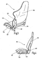
- eine perspektivische Ansicht der Struktur des ersten Ausführungsbeispiels von schräg vorne,
- Fig. 2
- einen schematisierten Schnitt durch einen Rastmechanismus,
- Fig. 3
- eine perspektivische Ansicht der Struktur des ersten Ausführungsbeispiels von schräg hinten,
- Fig. 4
- eine Seitenansicht des gepolsterten ersten Ausführungsbeispiels mit abgesenktem Seitenwangenbügel und gestrichtelt mit angehobenem Seitenwangenbügel,
- Fig. 5
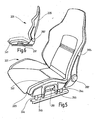
- eine perspektivische Ansicht des zweiten Ausführungsbeispiels von schräg vorne, und
- Fig. 6
- eine Seitenansicht des zweiten Ausführungsbeispiels mit abgesenktem Seitenwangenbügel und gestrichtelt mit angehobenem Seitenwangenbügel.
- Fig. 1
- a perspective view of the structure of the first embodiment obliquely from the front,
- Fig. 2
- a schematic section through a locking mechanism,
- Fig. 3
- a perspective view of the structure of the first embodiment obliquely from behind,
- Fig. 4
- a side view of the padded first embodiment with lowered side bolster and gestrichtelt with raised side cheekpiece,
- Fig. 5
- a perspective view of the second embodiment obliquely from the front, and
- Fig. 6
- a side view of the second embodiment with lowered side cheekpiece and gestrichtelt with raised side cheekpiece.
Im ersten Ausführungsbeispiel weist ein als Schalensitz ausgebildeter Sportsitz 101 eine einstückige, konturierte (d.h. mit angeformten, abgewinkelten Bereichen versehene), starre Sitzschale 103 als Struktur für das Sitzteil und eine gesondert ausgebildete, ebenfalls einstückige, stark konturierte, starre Lehnenschale 105 als Struktur für die Lehne auf. Die Lehnenschale 105 ist mittels Beschlägen 107 neigungseinstellbar an der Sitzschale 103 angebracht. Die Sitzschale 103 und die Lehnenschale 105 sind aus einem an sich bekannten Material gefertigt, beispielsweise aus einem Glasfaser-, einem Kohlefaser- oder einem Kunststoffmaterial, welches mit Glasfaser- oder Kohlefasermatten verstärkt ist. Die Polsterung der Sitzschale 103 und der Lehnenschale 105 erfolgt auf an sich bekannte Weise mit Schaumstoff und einem Bezug, beispielsweise aus Leder.In the first embodiment, designed as a bucket
Die Beschläge 107 weisen jeweils relativ zueinander verdrehbare Beschlagunterteile und Beschlagoberteile auf. Zur Befestigung der Beschläge 107 sind die Seitenpartien der Sitzschale 103 und der Lehnenschale 105 bereichsweise eben ausgebildet und für eine Kraftaufnahme ausgelegt, d.h. beispielsweise verstärkt und/oder mit Sicken oder dergleichen versehen. Zusätzlich sind zur Vermeidung der Rißbildung im Bereich der Befestigungsbereiche Einlegeteile aus Metall oder hartem Kunststoff vor dem Verpressen in das Schalenmaterial eingelegt und dann mit diesem verpreßt worden. An die so verstärkten Seitenpartien der Sitzschale 103 bzw. der Lehnenschale 105 sind ein mit dem Beschlagunterteil verbundener Sitzteiladapter 133 bzw. ein mit dem Beschlagoberteil verbundener Lehnenadapter 135 flach angelegt und mittels Schrauben 137 angebracht oder anderweitig befestigt. Der Sitzteiladapter 133, welcher an seiner Unterseite abgewinkelt ausgebildet ist, dient zugleich als Unterbau zur Befestigung an der Fahrzeugstruktur oder optional an der Oberschiene eines Sitzschienenpaares. Die beiden Adapter 133 und 135 sind beim fertig gepolsterten Sportsitz 101 durch Kunststoffabdeckungen verblendet.The
Während an der Lehnenschale 105 die Seitenwangen angeformt sind, wird bei der Sitzschale 103 die Struktur der Seitenwange durch einen Seitenwangenbügel 141 definiert. Zumindest der schwellerseitige Seitenwangenbügel 141 ist an seinem hinteren Ende mittels eines um eine horizontale Achse schwenkenden Gelenks 143 an der Sitzschale 103 angelenkt. Am vorderen Ende ist der Seitenwangenbügel 141 mittels eines Rastmechanismus 145, bestehend aus einer sitzschalenfesten Rastleiste 147 und einem federbelastet im Seitenwangenbügel 141 gelagerten Rastbolzen 149, der durch ein druckknopfartiges Betätigungselement 151 aushebbar ist, lösbar arretiert. Für einen erleicherten Ausstieg kann der Insasse durch Druck auf das Betätigungselement 151 den Rastmechanismus 145 lösen und den dann höhenveränderlichen Seitenwangenbügel 141 nach unten schwenken, bis der abgesenkte Seitenwangenbügel 141 weitgehend unterhalb der Mittelbahn der gepolsterten Sitzschale 103 zu liegen kommt. Umgekehrt kann der Insasse nach dem erleichterten Einstieg den Seitenwangenbügel 141 in die oberste, gegenüber der Mittelbahn angehobenen Position schwenken, um während der Fahrt mit dem angehobenen Seitenwangenbügel 141 den maximalen Seitenhalt zu erzielen.While the side cheeks are integrally formed on the
Das zweite Ausführungsbeispiel gleicht dem ersten Ausführungsbeispiel, soweit nicht abweichend beschrieben, weshalb gleiche und gleichwirkende Bauteile um 100 höhere Bezugszeichen tragen. Auch bei diesem Sportsitz 201 sind die Sitzschale 203 und die Lehnenschale 205 mittels Beschlägen 207 auf die gleiche Weise wie im vorigen Ausführungsbeispiel miteinander gelenkig verbunden. Der schwellerseitige Seitenwangenbügel 241 ist nun linear verschieblich gelagert, indem er auf zwei vertikalen Säulen 244 sitzt und durch zwei Rastmechanismen 245 der beim ersten Ausführungsbeispiel beschriebenen Art arretiert ist, wobei die beiden Rastmechanismen 245 durch ein gemeinsames Betätigungselement 251 gekoppelt sind. Die Säulen 244 wiederum sind an einem Unterbau angebracht, welcher die Sitzschale 203 trägt. Das Betätigungselement 251 ist vorzugsweise als Handgriff ausgebildet und in der Mitte des symmetrisch ausgebildeten Seitenwangenbügels 241 angeordnet, so daß der Insasse mit dem Lösen des Rastmechanismus 245 zugleich das Verschieben des Seitenwangenbügels 241 vornehmen kann.The second embodiment is similar to the first embodiment, unless otherwise described, which is why the same and equivalent components wear by 100 higher reference numerals. Also in this
- 101, 201101, 201
- SportsitzSport seat
- 103, 203103, 203
- Sitzschaleseat
- 105, 205105, 205
- Lehnenschalebackrest shell
- 107, 207107, 207
- Beschlagfitting
- 133133
- SitzteiladapterSeat Adapters
- 135135
- Lehnenadapterbackrest adapter
- 137137
- Schraubescrew
- 141, 241141, 241
- SeitenwangenbügelSide cheek bow
- 143143
- Gelenkjoint
- 145, 245145, 245
- RastmechanimusRastmechanimus
- 147147
- Rastleistelocking strip
- 149149
- RastbolzenIndexing plungers
- 151, 251151, 251
- Betätigungselementactuator
- 244244
- Säulepillar
Claims (12)
- A sports seat for a vehicle, especially for a motor vehicle, having at least one rigid seat shell (103; 203) as a structure for the seat part and a separately formed, rigid backrest shell (105; 205) as a structure for the backrest, said shells being adjustable in inclination relative to each other by means of fittings (107; 207) which have a lower part connected fixedly to the seat shell (103; 203) and an upper part which is connected to the backrest shell (105; 205) and can be rotated relative to the lower part, characterized in that, for each fitting (107; 207), an adapter (133, 135) is respectively fitted to the lower part and upper part, and is fastened in each case to one of the shells (103, 105; 203, 205), for which the side parts of the shells (103, 105; 203, 205) are of flat design in some regions and designed for absorbing force.
- The sports seat as claimed in claim 1, characterized in that the regions in which the adapters (133, 135) are fastened to the shells (103, 105; 203, 205) are reinforced.
- The sports seat as claimed in claim 1 oder 2, characterized in that the regions in which the adapters (133, 135) are fastened to the shells (103, 105; 203, 205) are provided with beads.
- The sports seat as claimed in one of the preceding claims, characterized in that the shells (103, 105; 203, 205) are designed as a single-piece, contoured, and rigid.
- The sports seat as claimed in one of the preceding claims, characterized in that the shells (103, 105; 203; 205) are manufactured from a glass fiber material, a carbon fiber material or a plastic material, which is reinforced with mats of glass fibers or carbon fibers.
- The sports seat as claimed in claim 5, characterized in that in the fastening regions, inserts of metal or hard plastic have been placed into the shell material before the pressing takes place and have then been pressed to the latter.
- The sports seat as claimed in claim 2 or 6, characterized in that the adapters (133, 135) are placed flat onto the reinforced side parts of the shells (103, 105; 203, 205) and are fixed to them.
- The sports seat as claimed in one of the preceding claims, characterized in that in the completed padded sport seat (101), the two adapters (133, 135) are covered by plastic covers.
- The sports seat as claimed in one of the preceding claims, characterized in that the adapter (133) which is fastened to the seat shell (103; 203) serves at the same time as a substructure.
- The sports seat as claimed in one of the preceding claims, characterized in that the seat shell (103; 203) has, at least on the sill side, a moveable side cheek bow (141; 241) which is raised with respect to the central length to laterally grip the occupant and is lowered for entry and exit purposes.
- The sports seat as claimed in claim 10, characterized in that the side cheek bow (141) is coupled to the seat shell (103) or to an adapter (133) fastened to the seat shell (103).
- The sports seat as claimed in claim 10, characterized in that the side cheek bow (241) is fitted in a linearly displaceable manner to the seat shell (203) or to one of the adapters (233) fastened to the seat shell (203) or to a substructure supporting the seat shell (203).
Applications Claiming Priority (2)
| Application Number | Priority Date | Filing Date | Title |
|---|---|---|---|
| DE10327639A DE10327639A1 (en) | 2003-06-20 | 2003-06-20 | Sports seat for a vehicle, in particular for a motor vehicle |
| PCT/EP2004/006404 WO2004113114A2 (en) | 2003-06-20 | 2004-06-15 | Sports seat for a vehicle, especially for a motor vehicle |
Publications (2)
| Publication Number | Publication Date |
|---|---|
| EP1636062A2 EP1636062A2 (en) | 2006-03-22 |
| EP1636062B1 true EP1636062B1 (en) | 2009-12-30 |
Family
ID=33520731
Family Applications (1)
| Application Number | Title | Priority Date | Filing Date |
|---|---|---|---|
| EP04739879A Active EP1636062B1 (en) | 2003-06-20 | 2004-06-15 | Sports seat for a vehicle, especially for a motor vehicle |
Country Status (5)
| Country | Link |
|---|---|
| US (1) | US7131697B2 (en) |
| EP (1) | EP1636062B1 (en) |
| JP (1) | JP2007506598A (en) |
| DE (2) | DE10327639A1 (en) |
| WO (1) | WO2004113114A2 (en) |
Families Citing this family (40)
| Publication number | Priority date | Publication date | Assignee | Title |
|---|---|---|---|---|
| EP1781492A4 (en) * | 2004-08-12 | 2008-11-26 | Intier Automotive Inc | Adjustable seat cushion bolster mechanism |
| EP1866181A2 (en) * | 2005-04-08 | 2007-12-19 | Schukra Gerätebau AG | Regulating device for a lateral part of a seat and method for producing a lateral part |
| DE102005021482A1 (en) * | 2005-05-10 | 2006-11-16 | Johnson Controls Gmbh | vehicle seat |
| US20060273644A1 (en) * | 2005-05-18 | 2006-12-07 | Alan Sturt | Vehicle seat assembly having movable bolsters |
| DE102005044012B4 (en) * | 2005-09-14 | 2015-04-16 | Recaro Automotive Ltd. & Co. Kg | Vehicle seat, in particular sports seat |
| DE102005059854B4 (en) * | 2005-12-15 | 2008-10-16 | Recaro Gmbh & Co. Kg | Vehicle seat, in particular sports seat |
| DE102007050091A1 (en) * | 2007-10-19 | 2009-04-23 | GM Global Technology Operations, Inc., Detroit | Vehicle seat with a rotating back section |
| DE102008011246A1 (en) | 2008-02-22 | 2009-09-03 | Recaro Gmbh & Co. Kg | Vehicle seat i.e. motor vehicle seat for racing car, has inner seat shell moved relative to outer seat shell in case of rear crash under change of dimensions and shape of intermediate space |
| US7850247B2 (en) * | 2008-09-19 | 2010-12-14 | Lear Corporation | Vehicle seat assembly with polymeric cushion pan |
| US8087729B2 (en) * | 2008-12-09 | 2012-01-03 | Wolfgang K, Llc | Aircraft seat |
| CN101633332B (en) * | 2009-08-19 | 2014-07-30 | 浙江天成自控股份有限公司 | Safety protection latch mechanism of vehicle backrest |
| DE102011076628A1 (en) * | 2011-05-27 | 2012-11-29 | Robert Bosch Gmbh | Holding device and vehicle seat with improved side protection |
| JP5859265B2 (en) * | 2011-10-05 | 2016-02-10 | 日本発條株式会社 | Vehicle seat |
| US9061766B2 (en) | 2011-11-30 | 2015-06-23 | Burkley U. Kladde | Synchronous seat recline mechanism |
| FR3006259B1 (en) * | 2013-06-03 | 2016-10-21 | Renault Sa | VEHICLE FRONT SEAT SYSTEM |
| GB2515576A (en) * | 2013-06-28 | 2014-12-31 | Gordon Murray Design Ltd | Vehicle Seat |
| DE102013225478A1 (en) | 2013-08-30 | 2015-03-05 | Johnson Controls Gmbh | VEHICLE SEAT, ESPECIALLY MOTOR VEHICLE SEAT |
| JP6202734B2 (en) * | 2013-11-18 | 2017-09-27 | 株式会社タチエス | Sheet |
| JP6192221B2 (en) * | 2013-11-18 | 2017-09-06 | 株式会社タチエス | Sheet |
| US9987961B2 (en) | 2014-06-09 | 2018-06-05 | Lear Corporation | Adjustable seat assembly |
| US10328823B2 (en) | 2014-06-09 | 2019-06-25 | Lear Corporation | Adjustable seat assembly |
| JP6225845B2 (en) * | 2014-07-01 | 2017-11-08 | トヨタ紡織株式会社 | Vehicle seat |
| USD771399S1 (en) * | 2015-02-20 | 2016-11-15 | Jaguar Land Rover Limited | Dynamic front seat |
| US9884570B2 (en) | 2015-05-19 | 2018-02-06 | Lear Corporation | Adjustable seat assembly |
| US9845026B2 (en) | 2015-05-19 | 2017-12-19 | Lear Corporation | Adjustable seat assembly |
| US9661928B2 (en) | 2015-09-29 | 2017-05-30 | Lear Corporation | Air bladder assembly for seat bottoms of seat assemblies |
| JP2017094898A (en) * | 2015-11-24 | 2017-06-01 | トヨタ紡織株式会社 | Vehicular seat part |
| US9827888B2 (en) * | 2016-01-04 | 2017-11-28 | Lear Corporation | Seat assemblies with adjustable side bolster actuators |
| DE102016200193A1 (en) | 2016-01-11 | 2017-07-13 | Adient Luxembourg Holding S.à.r.l. | vehicle seat |
| USD805313S1 (en) * | 2016-04-04 | 2017-12-19 | Dr. Ing. H.C. F. Porsche Aktiengesellschaft | Vehicle seat |
| DE102016215048B4 (en) * | 2016-08-12 | 2023-10-12 | Lear Corp. | Seat assembly and method of assembling a seat assembly |
| USD853741S1 (en) * | 2016-09-28 | 2019-07-16 | James Leckey Design Limited | Body support structures (seats) |
| JP6718785B2 (en) * | 2016-10-04 | 2020-07-08 | 株式会社タチエス | Vehicle seat |
| USD837551S1 (en) * | 2016-11-30 | 2019-01-08 | Jaguar Land Rover Limited | Vehicle seat |
| USD880883S1 (en) * | 2017-10-31 | 2020-04-14 | Homy Casa Limited | Swivel chair |
| US10351024B2 (en) * | 2017-11-30 | 2019-07-16 | Ford Global Technologies, Llc | Ovoid seating assembly |
| JP6973291B2 (en) | 2018-05-22 | 2021-11-24 | トヨタ紡織株式会社 | Vehicle seat |
| USD905984S1 (en) * | 2019-02-22 | 2020-12-29 | Adient Engineering and IP GmbH | Vehicle seat |
| US11396253B1 (en) * | 2021-03-15 | 2022-07-26 | Ford Global Technologies, Llc | Adjustment mechanism for seating assembly member |
| US20240083318A1 (en) * | 2022-09-08 | 2024-03-14 | GM Global Technology Operations LLC | Vehicle including a seat having reconfigurable bolsters |
Family Cites Families (23)
| Publication number | Priority date | Publication date | Assignee | Title |
|---|---|---|---|---|
| DE1755333C3 (en) | 1968-04-27 | 1981-02-05 | Recaro Gmbh & Co, 7000 Stuttgart | Bucket seats for automobiles |
| FR2007080A1 (en) * | 1968-04-27 | 1970-01-02 | Recaro Ag | |
| DE2235823A1 (en) * | 1972-07-21 | 1974-01-31 | Porsche Ag | BUCKET SEAT FOR PASSENGER CARS |
| US4169626A (en) * | 1978-07-17 | 1979-10-02 | General Motors Corporation | Reclining vehicle seat |
| DE2951645C2 (en) * | 1979-12-21 | 1986-05-22 | Keiper Recaro GmbH & Co, 7312 Kirchheim | Bucket seat |
| DE8033029U1 (en) * | 1980-12-12 | 1982-12-09 | Audi Nsu Auto Union Ag, 7107 Neckarsulm | BUCKET SEAT FOR A MOTOR VEHICLE |
| DE8107872U1 (en) * | 1981-03-18 | 1981-10-08 | Kißling, Wolfgang, Dipl.-Ing., 7000 Stuttgart | "BUCKET SEAT" |
| DE3274633D1 (en) * | 1981-12-23 | 1987-01-22 | Keiper Recaro Gmbh Co | Vehicle seat |
| DE3151018A1 (en) | 1981-12-23 | 1983-07-28 | Keiper Recaro GmbH & Co, 7312 Kirchheim | Vehicle seat, in particular motor vehicle seat |
| DE3216060A1 (en) | 1982-04-30 | 1983-11-03 | Keiper Recaro GmbH & Co, 7312 Kirchheim | Vehicle seat, in particular a motor vehicle seat |
| JPS61215132A (en) * | 1985-03-19 | 1986-09-24 | Ikeda Bussan Co Ltd | Bucket seat for vehicles |
| FR2623758B1 (en) * | 1987-11-26 | 1990-05-04 | Peugeot Cycles | DEVICE FOR REDUCING THE SIDE WING OF A SEAT AND A BUCKET SEAT FOR A MOTOR VEHICLE OR THE LIKE COMPRISING SUCH A DEVICE |
| DE4220471A1 (en) * | 1992-06-23 | 1993-04-15 | Roland Glomb | Sports car seat with folding side pommel - has hinges which can be operated manually, by Bowden cable or by an electric motor |
| US5328236A (en) * | 1992-09-29 | 1994-07-12 | Tachi-S Col. Ltd. | Side support device in seat back of an automotive seat |
| US5344215A (en) * | 1993-03-10 | 1994-09-06 | Milsco Manufacturing Company | Backrest recliner mechanism |
| WO1998008705A1 (en) * | 1996-08-29 | 1998-03-05 | Lear Corporation | Vehicle seat assembly |
| DE19904299C1 (en) * | 1999-01-28 | 2000-06-08 | Keiper Gmbh & Co | Locking fitting for vehicle seat, with transmission element in form of axial lock to hold fitting parts together |
| US6039402A (en) * | 1999-02-12 | 2000-03-21 | Tachi-S Co., Ltd. | Seat provided with a seat climbing/descending aid structure for easy climbing onto and descending from the seat, and a seat climbing/descending aid designed for that purpose |
| US6802563B1 (en) * | 2000-03-06 | 2004-10-12 | Lear Corporation | Adjustable seat bolsters |
| DE10037327A1 (en) * | 2000-07-29 | 2002-02-14 | Keiper Gmbh & Co | Vehicle seat with adjustable seat cushion |
| US20050168041A1 (en) * | 2000-10-04 | 2005-08-04 | Glance Patrick M. | Thin, double-wall molded seat frame system |
| US6672666B2 (en) * | 2001-12-03 | 2004-01-06 | GRA★MAG Truck Interior Systems, L.L.C. | Mesh seat with displaceable bolsters |
| JP4050511B2 (en) * | 2001-12-20 | 2008-02-20 | 株式会社デルタツーリング | Seat structure |
-
2003
- 2003-06-20 DE DE10327639A patent/DE10327639A1/en not_active Withdrawn
-
2004
- 2004-06-15 EP EP04739879A patent/EP1636062B1/en active Active
- 2004-06-15 DE DE502004010590T patent/DE502004010590D1/en active Active
- 2004-06-15 WO PCT/EP2004/006404 patent/WO2004113114A2/en active Application Filing
- 2004-06-15 JP JP2006515928A patent/JP2007506598A/en active Pending
-
2005
- 2005-12-02 US US11/292,969 patent/US7131697B2/en active Active
Also Published As
| Publication number | Publication date |
|---|---|
| DE502004010590D1 (en) | 2010-02-11 |
| WO2004113114A2 (en) | 2004-12-29 |
| US7131697B2 (en) | 2006-11-07 |
| JP2007506598A (en) | 2007-03-22 |
| WO2004113114A3 (en) | 2006-04-20 |
| DE10327639A1 (en) | 2005-01-13 |
| US20060082208A1 (en) | 2006-04-20 |
| EP1636062A2 (en) | 2006-03-22 |
Similar Documents
| Publication | Publication Date | Title |
|---|---|---|
| EP1636062B1 (en) | Sports seat for a vehicle, especially for a motor vehicle | |
| EP0054948B1 (en) | Driver stand | |
| EP2059410B1 (en) | Vehicle seat, in particular motor vehicle seat | |
| EP1817198B1 (en) | Vehicle seat in particular motor vehicle seat | |
| DE102006045387B4 (en) | Backrest for motor vehicle seat, has backrest head module inserted in backrest frame, where backrest head module is retained pivotably about hinge axis that runs between lateral pieces in region of frame upper part | |
| EP0689954A2 (en) | Seat arrangement, especially for the load or passenger compartment of a motor vehicle | |
| DE4126520C2 (en) | ||
| DE19838734B4 (en) | Rear seat assembly for a motor vehicle | |
| DE102018120643A1 (en) | SWIVELED ASSEMBLED MECHANICAL PANEL EDITING CONNECTION SYSTEM FOR PUBLIC DISCHARGE | |
| DE19958676C1 (en) | Automobile rear passenger seat has backrest pivoted into stowed position immediately behind backrest of front passenger seat via pairs of levers on either side of backrest | |
| DE10258165B4 (en) | Removable vehicle seat | |
| DE102005022416B4 (en) | Headrest for a vehicle seat | |
| DE4129671C2 (en) | Vehicle seat | |
| WO2019043077A1 (en) | Revolving arrangement for an operator's compartment, in particular for vehicles, and vehicle | |
| DE19835831C2 (en) | Trim arrangement for motor vehicle seat | |
| EP1754623B1 (en) | Vehicle with adjustable rear seat | |
| DE4343108C1 (en) | Rear seat bench for a vehicle | |
| DE10034441A1 (en) | Automobile seat assembly has a rigid L-shaped frame to hold the seat and backrest frame sections with easy adjustments to position and alignment according to the stature of the occupant | |
| DE19849994C5 (en) | vehicle seat | |
| WO2008037754A2 (en) | Backrest for a motor vehicle and motor vehicle seat | |
| DE19751458A1 (en) | Swivel seat for a vehicle | |
| DE102006045516B3 (en) | Vehicle seat, particularly motor vehicle seat, comprises shell as supporting structure of backrest, where carrier is attached at shell arranged at side facing passenger, and sliding carriage is moved in longitudinal direction | |
| DE19634729A1 (en) | Seating arrangement for vehicles | |
| DE102009016061B4 (en) | Storage for vehicle seats | |
| DE2547630A1 (en) | TRUCK CAB |
Legal Events
| Date | Code | Title | Description |
|---|---|---|---|
| PUAI | Public reference made under article 153(3) epc to a published international application that has entered the european phase |
Free format text: ORIGINAL CODE: 0009012 |
|
| 17P | Request for examination filed |
Effective date: 20051007 |
|
| AK | Designated contracting states |
Kind code of ref document: A2 Designated state(s): AT BE BG CH CY CZ DE DK EE ES FI FR GB GR HU IE IT LI LU MC NL PL PT RO SE SI SK TR |
|
| AX | Request for extension of the european patent |
Extension state: AL HR LT LV MK |
|
| PUAK | Availability of information related to the publication of the international search report |
Free format text: ORIGINAL CODE: 0009015 |
|
| DAX | Request for extension of the european patent (deleted) | ||
| RBV | Designated contracting states (corrected) |
Designated state(s): DE ES FR GB IT |
|
| 17Q | First examination report despatched |
Effective date: 20080611 |
|
| GRAP | Despatch of communication of intention to grant a patent |
Free format text: ORIGINAL CODE: EPIDOSNIGR1 |
|
| GRAS | Grant fee paid |
Free format text: ORIGINAL CODE: EPIDOSNIGR3 |
|
| GRAA | (expected) grant |
Free format text: ORIGINAL CODE: 0009210 |
|
| AK | Designated contracting states |
Kind code of ref document: B1 Designated state(s): DE ES FR GB IT |
|
| REG | Reference to a national code |
Ref country code: GB Ref legal event code: FG4D Free format text: NOT ENGLISH |
|
| REF | Corresponds to: |
Ref document number: 502004010590 Country of ref document: DE Date of ref document: 20100211 Kind code of ref document: P |
|
| PG25 | Lapsed in a contracting state [announced via postgrant information from national office to epo] |
Ref country code: ES Free format text: LAPSE BECAUSE OF FAILURE TO SUBMIT A TRANSLATION OF THE DESCRIPTION OR TO PAY THE FEE WITHIN THE PRESCRIBED TIME-LIMIT Effective date: 20100410 |
|
| PLBE | No opposition filed within time limit |
Free format text: ORIGINAL CODE: 0009261 |
|
| STAA | Information on the status of an ep patent application or granted ep patent |
Free format text: STATUS: NO OPPOSITION FILED WITHIN TIME LIMIT |
|
| 26N | No opposition filed |
Effective date: 20101001 |
|
| REG | Reference to a national code |
Ref country code: GB Ref legal event code: 732E Free format text: REGISTERED BETWEEN 20120119 AND 20120125 |
|
| REG | Reference to a national code |
Ref country code: DE Ref legal event code: R082 Ref document number: 502004010590 Country of ref document: DE |
|
| REG | Reference to a national code |
Ref country code: DE Ref legal event code: R081 Ref document number: 502004010590 Country of ref document: DE Owner name: RECARO AUTOMOTIVE LTD. & CO. KG, DE Free format text: FORMER OWNER: RECARO GMBH & CO. KG, 73230 KIRCHHEIM, DE Effective date: 20120228 Ref country code: DE Ref legal event code: R081 Ref document number: 502004010590 Country of ref document: DE Owner name: ADIENT LUXEMBOURG HOLDING S.A.R.L., LU Free format text: FORMER OWNER: RECARO GMBH & CO. KG, 73230 KIRCHHEIM, DE Effective date: 20120228 Ref country code: DE Ref legal event code: R081 Ref document number: 502004010590 Country of ref document: DE Owner name: ADIENT LUXEMBOURG HOLDING S.A R.L., LU Free format text: FORMER OWNER: RECARO GMBH & CO. KG, 73230 KIRCHHEIM, DE Effective date: 20120228 |
|
| REG | Reference to a national code |
Ref country code: DE Ref legal event code: R081 Ref document number: 502004010590 Country of ref document: DE Owner name: RECARO AUTOMOTIVE LTD. & CO. KG, DE Free format text: FORMER OWNER: RECARO AUTOMOTIVE GMBH & CO. KG, 73230 KIRCHHEIM, DE Effective date: 20130724 Ref country code: DE Ref legal event code: R081 Ref document number: 502004010590 Country of ref document: DE Owner name: ADIENT LUXEMBOURG HOLDING S.A.R.L., LU Free format text: FORMER OWNER: RECARO AUTOMOTIVE GMBH & CO. KG, 73230 KIRCHHEIM, DE Effective date: 20130724 Ref country code: DE Ref legal event code: R081 Ref document number: 502004010590 Country of ref document: DE Owner name: ADIENT LUXEMBOURG HOLDING S.A R.L., LU Free format text: FORMER OWNER: RECARO AUTOMOTIVE GMBH & CO. KG, 73230 KIRCHHEIM, DE Effective date: 20130724 |
|
| REG | Reference to a national code |
Ref country code: FR Ref legal event code: CD Owner name: RECARO AUTOMOTIVE LTD. & CO. KG, DE Effective date: 20130916 |
|
| REG | Reference to a national code |
Ref country code: FR Ref legal event code: PLFP Year of fee payment: 13 |
|
| REG | Reference to a national code |
Ref country code: DE Ref legal event code: R081 Ref document number: 502004010590 Country of ref document: DE Owner name: ADIENT LUXEMBOURG HOLDING S.A.R.L., LU Free format text: FORMER OWNER: RECARO AUTOMOTIVE LTD. & CO. KG, 73230 KIRCHHEIM, DE Ref country code: DE Ref legal event code: R081 Ref document number: 502004010590 Country of ref document: DE Owner name: RECARO AUTOMOTIVE GMBH, DE Free format text: FORMER OWNER: RECARO AUTOMOTIVE LTD. & CO. KG, 73230 KIRCHHEIM, DE Ref country code: DE Ref legal event code: R081 Ref document number: 502004010590 Country of ref document: DE Owner name: ADIENT LUXEMBOURG HOLDING S.A R.L., LU Free format text: FORMER OWNER: RECARO AUTOMOTIVE LTD. & CO. KG, 73230 KIRCHHEIM, DE |
|
| REG | Reference to a national code |
Ref country code: FR Ref legal event code: PLFP Year of fee payment: 14 |
|
| REG | Reference to a national code |
Ref country code: GB Ref legal event code: 732E Free format text: REGISTERED BETWEEN 20180111 AND 20180117 |
|
| REG | Reference to a national code |
Ref country code: DE Ref legal event code: R081 Ref document number: 502004010590 Country of ref document: DE Owner name: RECARO AUTOMOTIVE GMBH, DE Free format text: FORMER OWNER: ADIENT LUXEMBOURG HOLDING S.A.R.L., LUXEMBOURG, LU Ref country code: DE Ref legal event code: R081 Ref document number: 502004010590 Country of ref document: DE Owner name: ADIENT LUXEMBOURG HOLDING S.A R.L., LU Free format text: FORMER OWNER: ADIENT LUXEMBOURG HOLDING S.A.R.L., LUXEMBOURG, LU |
|
| REG | Reference to a national code |
Ref country code: FR Ref legal event code: TP Owner name: ADIENT LUXEMBOURG HOLDING S.A.R.L., LU Effective date: 20180314 |
|
| REG | Reference to a national code |
Ref country code: FR Ref legal event code: PLFP Year of fee payment: 15 |
|
| REG | Reference to a national code |
Ref country code: DE Ref legal event code: R082 Ref document number: 502004010590 Country of ref document: DE |
|
| REG | Reference to a national code |
Ref country code: DE Ref legal event code: R082 Ref document number: 502004010590 Country of ref document: DE Ref country code: DE Ref legal event code: R081 Ref document number: 502004010590 Country of ref document: DE Owner name: RECARO AUTOMOTIVE GMBH, DE Free format text: FORMER OWNER: ADIENT LUXEMBOURG HOLDING S.A R.L., LUXEMBOURG, LU |
|
| PGFP | Annual fee paid to national office [announced via postgrant information from national office to epo] |
Ref country code: FR Payment date: 20230630 Year of fee payment: 20 Ref country code: DE Payment date: 20230504 Year of fee payment: 20 |
|
| PGFP | Annual fee paid to national office [announced via postgrant information from national office to epo] |
Ref country code: IT Payment date: 20230623 Year of fee payment: 20 Ref country code: GB Payment date: 20230615 Year of fee payment: 20 |