EP1030336A2 - Elektrisches Installationsschaltgerät - Google Patents
Elektrisches Installationsschaltgerät Download PDFInfo
- Publication number
- EP1030336A2 EP1030336A2 EP00101252A EP00101252A EP1030336A2 EP 1030336 A2 EP1030336 A2 EP 1030336A2 EP 00101252 A EP00101252 A EP 00101252A EP 00101252 A EP00101252 A EP 00101252A EP 1030336 A2 EP1030336 A2 EP 1030336A2
- Authority
- EP
- European Patent Office
- Prior art keywords
- auxiliary switch
- switching device
- narrow side
- installation switching
- contact point
- Prior art date
- Legal status (The legal status is an assumption and is not a legal conclusion. Google has not performed a legal analysis and makes no representation as to the accuracy of the status listed.)
- Granted
Links
Images


Classifications
-
- H—ELECTRICITY
- H01—ELECTRIC ELEMENTS
- H01H—ELECTRIC SWITCHES; RELAYS; SELECTORS; EMERGENCY PROTECTIVE DEVICES
- H01H50/00—Details of electromagnetic relays
- H01H50/54—Contact arrangements
- H01H50/541—Auxiliary contact devices
- H01H50/545—Self-contained, easily replaceable microswitches
-
- H—ELECTRICITY
- H01—ELECTRIC ELEMENTS
- H01H—ELECTRIC SWITCHES; RELAYS; SELECTORS; EMERGENCY PROTECTIVE DEVICES
- H01H50/00—Details of electromagnetic relays
- H01H50/02—Bases; Casings; Covers
- H01H50/04—Mounting complete relay or separate parts of relay on a base or inside a case
- H01H50/041—Details concerning assembly of relays
- H01H2050/046—Assembling parts of a relay by using snap mounting techniques
Definitions
- the invention relates to an electrical installation switching device according to the preamble of claim 1.
- Installation switching devices in this context are motor protection switches, Sagittarius and the like, which have at least one single or double contact point have and the housing has approximately a T-shape. Is located the mounting surface with which the service switching device is mounted on a top-hat rail or the like can be attached to the free longitudinal surface of the crossbar T shape.
- a front front surface runs parallel to this on the end face of the longitudinal web the T-shape and two rear front surfaces on the crossbar of the T-shape; Farther are perpendicular narrow side walls on the end faces of the crossbar and provided on the side surfaces of the longitudinal web.
- the switching position of the contact point of the installation switching device is usually by means of of an auxiliary switch is detected and displayed.
- the object of the invention is an electrical installation device of the aforementioned To create type in which the auxiliary switch in a simple manner and space-saving on Installation switching device can be set.
- the auxiliary switch can then be attached to one of the narrow side walls and via one the coupling element actuating the auxiliary switch contact point, which is transverse to the narrow side wall runs, can be coupled to the movable contact piece.
- the width of the auxiliary switch corresponds to the module width of a motor protection switch pole.
- the auxiliary switch is preferably on the front Narrow side wall attached, i.e. on the narrow side wall that between the front and rear faces.
- the coupling element is advantageously a slide, which under the force of a Spring against the movable contact piece, for example against a contact bridge or against a reversing lever connected to the contact bridge against the contact lever is pressed.
- the auxiliary switch can preferably be a microswitch which is in the auxiliary switch housing is housed; on the coupling element, d. H. there is one on the slide Cam surface provided, the microswitch when moving the slide back and forth operated.
- locking elements can be provided with which the auxiliary switch housing are fixed to the housing of the installation switching device can.
- auxiliary switch housing is on the narrow side wall between the front and the rear front surface, there can be a folding around a lying in the area of the front face, parallel to the swivel axis the switching knob or pivot axis extending to the mounting rail; it is also possible to swivel the auxiliary switch housing around an axis, which is perpendicular to the floor surface near the edge in which the between of the front face and the rear face located in the adjacent broad side wall merges.
- the auxiliary switch can be in the Area of the rear front swivel axis that is parallel to the longitudinal extent the mounting rail of the installation switching device runs, pivoted be, the auxiliary switch about this pivot axis in a circular arc against the front Narrow side wall is pivoted; this is in sub-claims 10 to 13 shown.
- Fig. 1 shows a motor circuit breaker 10 with a housing 11 which has a T-shape has with a cross bar 12 and a longitudinal bar 13.
- the cross bar 12 runs parallel to the mounting surface 14 of the motor protection switch 10 and has one on it not shown recess with a fixed nose and a movable Nose, behind which a top-hat rail, also not shown, in the assembled Grab condition.
- the motor protection switch 10 has a front front surface 17 and two rear front surfaces 18, 18a, one from the front front surface 17 Knob 19 protrudes. Between the front face 17 in the face of the longitudinal web 13, and the two rear front surfaces 18, 18a are located front narrow side walls 20 and 20a, and between the rear front surfaces 18, 18a and the fastening surface 14, rear narrow side surfaces 21, 21a are provided. All narrow side surfaces run approximately perpendicular to the front surface 17 or to Mounting surface 14.
- the motor protection switch has a switch lock, which is connected to the rotary knob 19 is a bimetallic strip, a magnetic release and an arc extinguishing arrangement. It also includes a fixed contact piece with one a movable contact piece attached to a contact lever cooperates or a Double contact point.
- Fig. 1 shows an auxiliary switch block 25 which on the front narrow side wall 20a to be attached.
- the auxiliary switch block 25 has a width that the module width the motor protection switch 10 corresponds, and a height that the height of the front Narrow side wall, measured perpendicular to the mounting plane 14, corresponds. On in this way, the auxiliary switch block 25 does not project beyond the broad sides 22 or the front side 17th
- a pin 27 On the housing of the auxiliary switch block 25 is on the surface 26, which in the assembled state touches the narrow side surface 20a, a pin 27 is attached, which in a recess 28 engages on the front narrow side wall 20a; the pin 27 and the The recess or opening 28 form an axis of rotation about which the auxiliary switch 25 in Arrow direction P can be pivoted when the auxiliary switch 25 to the front Narrow side wall 20a is attached.
- a fixing pin 29 attached, which is parallel to the guide pin 27 and perpendicular to the Side wall 26 of the auxiliary switch 25 extends.
- the free end of the fixation pin 29 has a nail head-like extension 30, which when assembled in an upper section 31 of an arcuate recess 32 can be inserted, which recess 32 tapers down to the rear front wall 18a, so that after inserting the Fixing pin 29 and pivoting the auxiliary switch 50 in the direction of arrow P the Fixing pin 29 enters the lower region 33 of the recess 32, the Head 30 gets behind the tapered edges of the recess 32 and so the Auxiliary switch block 25 is fixed.
- An actuating tappet protrudes from an opening 34 in the front narrow side wall 20a 35, the one with the contact bridge or with the movable contact piece is connected and represents the coupling element, which in the assembled state in the auxiliary switch 25 engages and contacts located there opens or closes, depending on Design of the auxiliary switch block.
- the structure of the motor protection switch according to FIGS. 2 and 3 corresponds essentially to that Execution of the motor protection switch 10 of FIG. 1, also with respect to Design and external shape of the motor protection switch referred to FIG. 1 becomes.
- FIG. 2 shows a motor protection switch 50 on its front narrow side wall 51, which lies between the front front wall 52 and the rear front wall 53
- Auxiliary switch 54 can be connected, which is essentially the auxiliary switch 25 of FIG. 1 corresponds; for this purpose the auxiliary switch is about an axis 55 which is parallel to the Hat profile mounting rail 16 runs and between the front surface 52 and the narrow side surface 51 lies, rotatable.
- auxiliary switch 54 To rotate the auxiliary switch 54 about the axis 55 are on its upper edge 54a, which is adjacent to the front face 52 in the assembled state, two L-shaped ones Latches 54b and 54c attached, which in the position shown in Fig. 2 Auxiliary switch 54 in recesses 52a and 52b arranged on the front side 52 be used; Fig. 2 shows that the auxiliary switch block with its front Narrow side wall adjacent surface forms an angle with this, which to the rear Front surface 53 is open.
- auxiliary switch 54 are on the adjacent edge of the auxiliary switch 54 further locking arms 56 are provided, which are adjacent to the front narrow side surface 51 Protruding wall of the auxiliary switch 54 and when swiveling, that is, at Rotating the auxiliary switch 54 about the axis of rotation 55 in recesses 57 on the broad sides 58 intervene to lock the auxiliary switch 54.
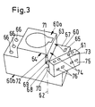
- FIG. 3 shows a view of a motor protection switch 60 on which an auxiliary switch 61 is connected about an axis 62 which is perpendicular to the mounting plane in the edge between the front narrow side wall 63 and the adjacent broad side wall 64 runs, pivoted against the front narrow side wall 63 and thereby is locked.
- Two openings 65 and 66 can be seen through the connecting terminals can be operated and in the rear front surfaces 67 and 67a, which correspond to the front surfaces 18 and 18a.
- auxiliary switch or auxiliary switch block adjacent to the axis of rotation 62 61 which runs perpendicular to the fastening plane 60b or to the front surface 60a, are latching lugs 69 corresponding to the latching lugs 54b and 54c on the auxiliary switch 61 and 70 attached, which in corresponding recesses 71 and 72 on the broad side 64 intervene.
- the auxiliary switch 61 can about the axis of rotation 62 against the front narrow side surface 63 can be pivoted. That then a corresponding locking of the Auxiliary switch block 61 is necessary, of course.
- the transmission also takes place the contact movement within the motor protection switch 60 on the contact pieces of the auxiliary switch 61 similar to that of the embodiments according to FIGS. 1 and 2.
- Each of the auxiliary switches of Figs. 1, 2 and 3 has on the parallel to the front wall extending front surface 73 openings 74 through which a screwdriver a terminal is accessible, as well as on the outside, parallel to the front Narrow side surface 63 extending side surface 75 openings 76 through which Connection lines can be inserted into the interior of the auxiliary switch 61.
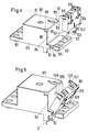
- FIG. 4 shows an installation switching device 80 with a front front surface 81 and two rear front surfaces 82 and 83, with further sections of the installation switching device are not shown since these further sections are not important.
- front narrow side surface 84 there is a front narrow side surface 84, and perpendicular to the front face and the rear face 83 and of the front narrow side surface 84 run on both sides of broad side walls 85 the corners at which the connecting edges of the broad side surfaces 85 and Narrow side surface 84 and the front front surface 18 meet which corners with the reference numerals 86 and 87, starting from the broad side surfaces, Locking recesses 88 and 89 arranged, each having a locking edge 90 and 91 have, which run parallel to the front narrow side surface.
- Broad side surfaces 85 are also recesses in the area of the rear front surface 83 92, 93 introduced, which have a nose 94, the nose edges run parallel to the front narrow side surface 84. This creates undercuts 95.
- An auxiliary switch 96 is to be attached to the front narrow side surface 84, which has a rectangular, cuboid shape.
- the distance of the swivel axis S-S from the front narrow side surface corresponds about the thickness of the auxiliary switch 96, in the direction perpendicular to the front narrow side surface measured.
Landscapes
- Physics & Mathematics (AREA)
- Electromagnetism (AREA)
- Switch Cases, Indication, And Locking (AREA)
Abstract
Description
- Fig. 1 bis 3
- je eine perspektivische Ansicht eines Motorschutzschalters mit unterschiedlicher Anbringung eines Hilfsschalters, und
- Fig. 4 bis 6
- perspektivische Ansichten eines Motorschutzschalters mit unterschiedlichen Montagestellungen des Hilfsschalters.
Claims (13)
- Elektrisches Installationsschaltgerät, insbesondere Motorschutzschalter und dgl. mit wenigstens einer Einfach- oder Doppelkontaktstelle, mit einem dieser Kontaktstelle zugeordneten Hilfsschalter zur Schaltstellungsanzeige, dessen Schaltkontaktstelle mit dem beweglichen Kontaktstück der Einfach- oder Doppelkontaktstelle gekuppelt ist, mit einem etwa T-förmigen Gehäuse, das eine Befestigungsfläche am freien Quersteg der T-Form, etwa parallel dazu eine vordere Frontfläche an der Stirnseite des Längssteges der T-Form und zwei ebenfalls etwa parallel dazu verlaufende hintere Frontflächen am Querbalken der T-Form sowie senkrecht dazu verlaufende Schmalseitenwände an den Stirnflächen des Quersteges und an den Seitenflächen des Längssteges der T-Form und beidseitig und senkrecht zu den Front- und Schmalseitenwänden sowie senkrecht zur Befestigungsebene Breitseitenflächen aufweist, dadurch gekennzeichnet, daß der Hilfsschalter (25, 54, 61, 96) an einer der Schmalseitenwände (20a; 51, 63, 84) ansetzbar und daran verrastbar und über ein die Hilfsschalterkontaktstelle betätigendes Kuppelelement, das etwa senkrecht zu der Schmalseitenwand (20a, 51, 63, 84) verläuft, mit dem beweglichen Kontaktstück der Einfach-oder Doppelkontaktstelle kuppelbar ist.
- Installationsschaltgerät nach Anspruch 1, dadurch gekennzeichnet, daß der Hilfsschalter (25, 54, 61, 96) mit seinem Kuppelelement an der vorderen Schmalseitenwand (20a, 51, 63, 84) zwischen der vorderen und der hinteren Frontfläche (17, 18a; 52, 53; 81, 83) einfügbar ist und so mit dem beweglichen Kontaktstück der Einfach-oder Doppelkontaktstelle in Eingriff gelangt.
- Installationsschaltgerät nach einem der vorigen Ansprüche, dadurch gekennzeichnet, daß das Kuppelelement ein Schieber ist, der die im Hilfsschalter befindliche Kontaktstelle betätigt.
- Installationsschaltgerät nach einem der Ansprüche 1 und 2, dadurch gekennzeichnet, daß das Kuppelelement ein Schwenkhebel ist.
- Installationsschaltgerät nach einem der vorigen Ansprüche, dadurch gekennzeichnet, daß die Hilfsschalterkontaktstelle ein Mikroschalter ist.
- Installationsschaltgerät nach Anspruch 5, dadurch gekennzeichnet, daß der Schieber eine Nockenfläche aufweist, die den Mikroschalter betätigt.
- Installationsschaltgerät nach einem der vorigen Ansprüche, dadurch gekennzeichnet, daß im Hilfsschaltergehäuse Anschlußklemmen für den Hilfsschalter vorgesehen sind, die von der Frontseite aus betätigbar sind.
- Installationsschaltgerät nach einem der vorigen Ansprüche, dadurch gekennzeichnet, daß der Hilfsschalter um eine in der Verbindungsecke zwischen der vorderen Frontfläche und einer vorderen Seitenflächen liegenden Achse schwenkbar ist (Fig. 2)
- Installationsschaltgerät nach einem der Ansprüche 1 bis 7, dadurch gekennzeichnet, daß der Hilfsschalter um eine in der Verbindungsecke zwischen der Breitseitenfläche und der vorderen Schmalseitenfläche liegende Achse an die vordere Schmalseitenfläche anschwenkbar ist (Fig. 3).
- Installationsschaltgerät nach einem der Ansprüche 1 bis 7, dadurch gekennzeichnet, daß der Hilfsschalter (96) um eine im Bereich der hinteren Frontfläche (83) gelegene Achse (S-S) an die vordere Schmalseitenfläche (84) anschwenkbar und daran verrastbar ist.
- Installationsschaltgerät nach Anspruch 10, dadurch gekennzeichnet, daß an der der hinteren Frontfläche (83) benachbarten unteren Fläche (97) des Hilfsschalters (96) an der Kante zwischen der der vorderen Schmalseite (84) entgegengesetzt liegenden Seitenfläche (99) und der hinteren Frontfläche (83) senkrecht zur letzteren zwei in Abstand zueinander liegende L-förmige Rastvorsprünge (100, 102) angeformt sind und daß an der hinteren Frontfläche (83) den Vorsprüngen bzw. Rastarmen (100, 102) entsprechende Ausnehmungen (92, 93) mit Hinterschneidungen (94, 95) vorgesehen sind, dergestalt, daß die freien Enden der L-förmigen Rastnasen (100, 102) hinter die Hinterschneidungen (94, 95) greifen und somit die Schwenkachse (S-S) bilden, um die der Hilfsschalter (99) gegen die vorderen Schmalseitenfläche (94) schwenkbar ist.
- Installationsschaltgerät nach einem der Ansprüche 10 und 11, dadurch gekennzeichnet, daß im Bereich der der vorderen Schmalseitenfläche (84) zugewandten Fläche des Hilfsschalters (96) senkrecht zu dieser Rastarme (106, 107) angeformt sind, die in angepaßte Rastvertiefungen (88, 89) am Installationsschaltgerät (80) eingreifen.
- Installationsschaltgerät nach einem der Ansprüche 10 bis 12, dadurch gekennzeichnet, daß die Rastvertiefungen (88, 89) von den Breitseiten (85) des Installationsschaltgerätes (80) ausgehen, und daß die Außenfläche der Rastarme (106, 107) und den zugehörigen Breitseitenflächen (85) etwa fluchten.
Applications Claiming Priority (4)
| Application Number | Priority Date | Filing Date | Title |
|---|---|---|---|
| DE19906235 | 1999-02-15 | ||
| DE19906235 | 1999-02-15 | ||
| DE19918577A DE19918577A1 (de) | 1999-02-15 | 1999-04-23 | Elektrisches Installationsschaltgerät |
| DE19918577 | 1999-04-23 |
Publications (3)
| Publication Number | Publication Date |
|---|---|
| EP1030336A2 true EP1030336A2 (de) | 2000-08-23 |
| EP1030336A3 EP1030336A3 (de) | 2001-05-09 |
| EP1030336B1 EP1030336B1 (de) | 2006-12-27 |
Family
ID=26051858
Family Applications (1)
| Application Number | Title | Priority Date | Filing Date |
|---|---|---|---|
| EP20000101252 Expired - Lifetime EP1030336B1 (de) | 1999-02-15 | 2000-01-25 | Elektrisches Installationsschaltgerät |
Country Status (2)
| Country | Link |
|---|---|
| EP (1) | EP1030336B1 (de) |
| DE (1) | DE50013892D1 (de) |
Cited By (4)
| Publication number | Priority date | Publication date | Assignee | Title |
|---|---|---|---|---|
| US7732723B2 (en) | 2004-01-19 | 2010-06-08 | Abb Oy | Auxiliary contact configuration for switching device |
| CN105895449A (zh) * | 2014-12-19 | 2016-08-24 | 黎平白娘子药业科研开发有限公司 | 一种组合多功能电源继电器座 |
| CN105895448A (zh) * | 2014-12-19 | 2016-08-24 | 黎平白娘子药业科研开发有限公司 | 一种新型电源继电器座 |
| CN116959924A (zh) * | 2023-08-31 | 2023-10-27 | 上海正泰智能科技有限公司 | 接触器辅助触头及接触器 |
Family Cites Families (4)
| Publication number | Priority date | Publication date | Assignee | Title |
|---|---|---|---|---|
| FR2521773B1 (fr) * | 1982-02-12 | 1985-06-07 | Telemecanique Electrique | Petit contacteur equipe d'un sous-ensemble d'interrupteurs auxiliaires amovible |
| FR2675624B1 (fr) * | 1991-04-22 | 1993-08-06 | Telemecanique | Appareil interrupteur electromecanique a bloc additif frontal. |
| DE9402477U1 (de) * | 1994-02-15 | 1994-04-07 | Szelinski, Jürgen, 44339 Dortmund | Optisch-akustischer Sicherungswächter |
| DE9403259U1 (de) * | 1994-02-26 | 1994-04-21 | Klöckner-Moeller GmbH, 53115 Bonn | Gehäuseaufbau für einen Niederspannungs-Schutzschalter mit Hilfsschalterblock |
-
2000
- 2000-01-25 EP EP20000101252 patent/EP1030336B1/de not_active Expired - Lifetime
- 2000-01-25 DE DE50013892T patent/DE50013892D1/de not_active Expired - Lifetime
Cited By (4)
| Publication number | Priority date | Publication date | Assignee | Title |
|---|---|---|---|---|
| US7732723B2 (en) | 2004-01-19 | 2010-06-08 | Abb Oy | Auxiliary contact configuration for switching device |
| CN105895449A (zh) * | 2014-12-19 | 2016-08-24 | 黎平白娘子药业科研开发有限公司 | 一种组合多功能电源继电器座 |
| CN105895448A (zh) * | 2014-12-19 | 2016-08-24 | 黎平白娘子药业科研开发有限公司 | 一种新型电源继电器座 |
| CN116959924A (zh) * | 2023-08-31 | 2023-10-27 | 上海正泰智能科技有限公司 | 接触器辅助触头及接触器 |
Also Published As
| Publication number | Publication date |
|---|---|
| DE50013892D1 (de) | 2007-02-08 |
| EP1030336B1 (de) | 2006-12-27 |
| EP1030336A3 (de) | 2001-05-09 |
Similar Documents
| Publication | Publication Date | Title |
|---|---|---|
| DE3885989T2 (de) | Gekapseltes Schaltbrett. | |
| DE69029689T2 (de) | Entwurf für Auslöse- und Verriegelungsmechanismus | |
| DE2639641C2 (de) | Bedienungsmechanismus für einen in einem Schaltschrank eingebauten elektrischen Schalter | |
| DE2835354A1 (de) | Sprungkontakt-schutzschalter | |
| DE9203532U1 (de) | Mechanischer Umschalt-, Parallel- oder Fernantrieb für elektrische Schaltgeräte mit Dreh- oder Kipphebelantrieb, insbesondere für Leistungstrenner, Motorschutzschalter und dergleichen | |
| EP1030337B1 (de) | Elektrisches Installationsschaltgerät | |
| WO2011137946A2 (de) | Elektrisches installationsschaltgerät mit einer schnellbefestigungsvorrichtung | |
| EP1030336B1 (de) | Elektrisches Installationsschaltgerät | |
| DE69507272T2 (de) | Anordnung zur Befestigung eines elektrischen Gerätes an einer Tragschiene | |
| EP2387059A2 (de) | Elektrisches Installationsschaltgerät mit einer Schnellbefestigungsvorrichtung | |
| EP1829178A1 (de) | Schnellbefestigung an einem elektrischen installationsgerät | |
| DE4011447C2 (de) | Vorrichtung zur Schnappbefestigung eines elektrischen Installationsgerätes | |
| DE4011447A9 (de) | Schnellbefestigung für ein elektrisches Installationsgerät | |
| EP0145946B1 (de) | Leitungsschutzschalter | |
| DE102020125730B3 (de) | Sicherungslasttrennschalter, insbesondere nh-sicherungslasttrennschalter | |
| DE19918577A1 (de) | Elektrisches Installationsschaltgerät | |
| DE29807106U1 (de) | Elektrisches Installationsgerät, insbesondere zur Aufputz-Montage | |
| EP1038109B1 (de) | Elektrisches gerät mit einem verbindungsclip und einer verbindungsclipaufnahme zur verbindung mit einem zweiten elektrischen gerät | |
| DE19934542C1 (de) | Schaltersicherungseinheit mit Halterverriegelung | |
| DE4405934C1 (de) | Blockierbaren Hauptschalter mit einer Vorrichtung zur Überwindung der Blockierung | |
| DE4211915C2 (de) | Prüftastenanordnung für einen Fehlerstrom- oder Differenzstromschutzschalter | |
| DE29520288U1 (de) | Fehlerstrom-Schutzschalter mit Montageteil | |
| EP0748014B1 (de) | Einrichtung zur etagenweisen Anordnung von Schaltgeräten | |
| DE10013102B4 (de) | Verbindungseinrichtung | |
| DE69010929T2 (de) | Verriegelungsbaustein für zwei elektrische Schaltgeräte mit gegossenem Miniaturgehäuse. |
Legal Events
| Date | Code | Title | Description |
|---|---|---|---|
| PUAI | Public reference made under article 153(3) epc to a published international application that has entered the european phase |
Free format text: ORIGINAL CODE: 0009012 |
|
| AK | Designated contracting states |
Kind code of ref document: A2 Designated state(s): DE FR IT |
|
| AX | Request for extension of the european patent |
Free format text: AL;LT;LV;MK;RO;SI |
|
| PUAL | Search report despatched |
Free format text: ORIGINAL CODE: 0009013 |
|
| AK | Designated contracting states |
Kind code of ref document: A3 Designated state(s): AT BE CH CY DE DK ES FI FR GB GR IE IT LI LU MC NL PT SE |
|
| AX | Request for extension of the european patent |
Free format text: AL;LT;LV;MK;RO;SI |
|
| RIC1 | Information provided on ipc code assigned before grant |
Free format text: 7H 01H 50/54 A, 7H 01H 71/46 B |
|
| 17P | Request for examination filed |
Effective date: 20010627 |
|
| RAP1 | Party data changed (applicant data changed or rights of an application transferred) |
Owner name: ABB PATENT GMBH |
|
| AKX | Designation fees paid |
Free format text: DE FR IT |
|
| GRAP | Despatch of communication of intention to grant a patent |
Free format text: ORIGINAL CODE: EPIDOSNIGR1 |
|
| GRAS | Grant fee paid |
Free format text: ORIGINAL CODE: EPIDOSNIGR3 |
|
| GRAA | (expected) grant |
Free format text: ORIGINAL CODE: 0009210 |
|
| AK | Designated contracting states |
Kind code of ref document: B1 Designated state(s): DE FR IT |
|
| REF | Corresponds to: |
Ref document number: 50013892 Country of ref document: DE Date of ref document: 20070208 Kind code of ref document: P |
|
| ET | Fr: translation filed | ||
| PLBE | No opposition filed within time limit |
Free format text: ORIGINAL CODE: 0009261 |
|
| STAA | Information on the status of an ep patent application or granted ep patent |
Free format text: STATUS: NO OPPOSITION FILED WITHIN TIME LIMIT |
|
| 26N | No opposition filed |
Effective date: 20070928 |
|
| REG | Reference to a national code |
Ref country code: FR Ref legal event code: PLFP Year of fee payment: 16 |
|
| PGFP | Annual fee paid to national office [announced via postgrant information from national office to epo] |
Ref country code: IT Payment date: 20150128 Year of fee payment: 16 |
|
| PGFP | Annual fee paid to national office [announced via postgrant information from national office to epo] |
Ref country code: FR Payment date: 20150122 Year of fee payment: 16 |
|
| PGFP | Annual fee paid to national office [announced via postgrant information from national office to epo] |
Ref country code: DE Payment date: 20160120 Year of fee payment: 17 |
|
| REG | Reference to a national code |
Ref country code: FR Ref legal event code: ST Effective date: 20160930 |
|
| PG25 | Lapsed in a contracting state [announced via postgrant information from national office to epo] |
Ref country code: FR Free format text: LAPSE BECAUSE OF NON-PAYMENT OF DUE FEES Effective date: 20160201 |
|
| PG25 | Lapsed in a contracting state [announced via postgrant information from national office to epo] |
Ref country code: IT Free format text: LAPSE BECAUSE OF NON-PAYMENT OF DUE FEES Effective date: 20160125 |
|
| REG | Reference to a national code |
Ref country code: DE Ref legal event code: R119 Ref document number: 50013892 Country of ref document: DE |
|
| PG25 | Lapsed in a contracting state [announced via postgrant information from national office to epo] |
Ref country code: DE Free format text: LAPSE BECAUSE OF NON-PAYMENT OF DUE FEES Effective date: 20170801 |