EP1030134A2 - Verdampferplatine - Google Patents
Verdampferplatine Download PDFInfo
- Publication number
- EP1030134A2 EP1030134A2 EP00101901A EP00101901A EP1030134A2 EP 1030134 A2 EP1030134 A2 EP 1030134A2 EP 00101901 A EP00101901 A EP 00101901A EP 00101901 A EP00101901 A EP 00101901A EP 1030134 A2 EP1030134 A2 EP 1030134A2
- Authority
- EP
- European Patent Office
- Prior art keywords
- end section
- side channel
- channel end
- capillary tube
- evaporator board
- Prior art date
- Legal status (The legal status is an assumption and is not a legal conclusion. Google has not performed a legal analysis and makes no representation as to the accuracy of the status listed.)
- Granted
Links
Images

Classifications
-
- F—MECHANICAL ENGINEERING; LIGHTING; HEATING; WEAPONS; BLASTING
- F25—REFRIGERATION OR COOLING; COMBINED HEATING AND REFRIGERATION SYSTEMS; HEAT PUMP SYSTEMS; MANUFACTURE OR STORAGE OF ICE; LIQUEFACTION SOLIDIFICATION OF GASES
- F25B—REFRIGERATION MACHINES, PLANTS OR SYSTEMS; COMBINED HEATING AND REFRIGERATION SYSTEMS; HEAT PUMP SYSTEMS
- F25B39/00—Evaporators; Condensers
- F25B39/02—Evaporators
- F25B39/022—Evaporators with plate-like or laminated elements
- F25B39/024—Evaporators with plate-like or laminated elements with elements constructed in the shape of a hollow panel
-
- F—MECHANICAL ENGINEERING; LIGHTING; HEATING; WEAPONS; BLASTING
- F25—REFRIGERATION OR COOLING; COMBINED HEATING AND REFRIGERATION SYSTEMS; HEAT PUMP SYSTEMS; MANUFACTURE OR STORAGE OF ICE; LIQUEFACTION SOLIDIFICATION OF GASES
- F25B—REFRIGERATION MACHINES, PLANTS OR SYSTEMS; COMBINED HEATING AND REFRIGERATION SYSTEMS; HEAT PUMP SYSTEMS
- F25B41/00—Fluid-circulation arrangements
- F25B41/30—Expansion means; Dispositions thereof
- F25B41/37—Capillary tubes
-
- F—MECHANICAL ENGINEERING; LIGHTING; HEATING; WEAPONS; BLASTING
- F25—REFRIGERATION OR COOLING; COMBINED HEATING AND REFRIGERATION SYSTEMS; HEAT PUMP SYSTEMS; MANUFACTURE OR STORAGE OF ICE; LIQUEFACTION SOLIDIFICATION OF GASES
- F25B—REFRIGERATION MACHINES, PLANTS OR SYSTEMS; COMBINED HEATING AND REFRIGERATION SYSTEMS; HEAT PUMP SYSTEMS
- F25B2400/00—Component parts or details not otherwise provided for in this subclass
- F25B2400/05—Compression system with heat exchange between particular parts of the system
- F25B2400/052—Compression system with heat exchange between particular parts of the system between the capillary tube and another part of the refrigeration cycle
-
- F—MECHANICAL ENGINEERING; LIGHTING; HEATING; WEAPONS; BLASTING
- F25—REFRIGERATION OR COOLING; COMBINED HEATING AND REFRIGERATION SYSTEMS; HEAT PUMP SYSTEMS; MANUFACTURE OR STORAGE OF ICE; LIQUEFACTION SOLIDIFICATION OF GASES
- F25B—REFRIGERATION MACHINES, PLANTS OR SYSTEMS; COMBINED HEATING AND REFRIGERATION SYSTEMS; HEAT PUMP SYSTEMS
- F25B2400/00—Component parts or details not otherwise provided for in this subclass
- F25B2400/05—Compression system with heat exchange between particular parts of the system
- F25B2400/054—Compression system with heat exchange between particular parts of the system between the suction tube of the compressor and another part of the cycle
Definitions
- the invention relates to an evaporator board with at least one arranged thereon Refrigerant channel, which at least one connected to a suction line outflow-side channel end section and which has at least one inflow-side, over a Capillary tube serving as a throttle with refrigerant channel end section having a refrigerant injection point formed by the capillary tube.
- the refrigerant channels according to the roll bond process or Z-bond method are produced, it is state of the art that within one to the drain-side end of a refrigerant channel covering the evaporator board connected suction pipe runs as a throttle capillary. This is over the drain-side channel end section over the inflow-side channel end section of the refrigerant channel and there by forming an injection point so-called stamping of the inflow-side channel end section on the Evaporator board fixed, with the embossing at the same time a separation between the inflow-side and thus the pressure-side area of the refrigerant channel and the discharge-side and thus suction-side area of the refrigerant channel is effected.
- the invention has for its object an evaporator board according to the Preamble of claim 1 with simple constructive measures in terms of To improve noise emissions.
- the noise level caused by the refrigerant flowing in through the injection point reduced, creating a cooling device in the living area without being bothersome and annoying the people in the living space to act can be set up, whereby the Quality of life within the living space has increased.
- the Lowering the noise level below the usual hearing threshold avoided that Incoming noise of the refrigerant is interpreted as a malfunction of the refrigeration device and customer service is unnecessarily called.
- the means as a fluidic the inflow Channel end section upstream pipe-like connector are formed, which serves to connect the capillary tube and which via elastic Connecting elements with the inflow-side channel end section and the outflow-side Channel end section is connected.
- the relocation of the injection point in the connector opens the Possibility of the cross section of the connector serving as an injection channel without Influence on the execution of the evaporator board, in particular on the design of the refrigerant channel arranged there, targeted, according to the needs To be able to choose requirements.
- the means as a fluidic the inflow Channel end section upstream, mechanically from the drain-side channel end section and fluidically decoupled connector are formed, to which the Capillary tube is connected.
- a particularly simple and in the Large-scale production is particularly reliable, with high reproducibility Achievable reduction in noise emissions because the refrigerant injection point only still via the connecting pipe serving as the injection channel with the evaporator board is connected so that those resulting from the injection process of the refrigerant Suggestions are more fully decoupled from the evaporator board.
- the tube-like connector within a in the Evaporator board recess is arranged.
- Such a design allows not only a particularly flat design for the Evaporator board but also a particularly simple manufacturing technology and reliable coupling of the capillary tube to the connector.
- the Connection point visible and thus with regard to a high quality of the Evaporator boards controllable by an inexpensive visual inspection. Further can be saved due to the recess, serving as an injection channel Connector be provided with sound-absorbing material.
- a particularly favorable decoupling of the connector serving as an injection point of the evaporator board arises if after a next advantageous Embodiment of the object of the invention is provided that the inflow side Channel end section with the connector connected to it at least over whose connection length is arranged within the recess.
- the tube-like connector is at least one frustoconical trained length section, on its smaller cross-sectional area equipped end the capillary tube is connected.
- a turbulent inflow of the Refrigerant in the connector at least largely avoided, which the Structure-borne noise on the evaporator board caused by the suggestions inflowing refrigerants are additionally reduced.
- a particularly low-noise evaporator variant results if after another preferred embodiment of the object of the invention is provided that the Capillary tube outside the drain-side channel end section the inflow-side Channel end section is supplied and fluidically connected to this.
- the capillary tube within the suction line into the The vicinity of the drain-side channel end section runs and at a distance from it led out of the suction line and connected to the connector.
- Such advantageous further training not only brings an improvement in Energy efficiency of the refrigerator, namely by pre-cooling the inside of the Suction tube running capillary tube with it, but creates through the separation the connection area of the suction pipe on the evaporator board from that of Capillary tube in a simple way a reduction of the through that The refrigerant flowing in the capillary tube causes the injection noise.
- the capillary tube is guided along the outer surface of the suction line and is connected to the connector.
- An evaporator board can be operated particularly quietly if after a last preferred embodiment of the subject of the invention provided is that at least the inflow-side channel end section and that for connecting the Capillary tube serving connector is embedded in soundproofing material.
- FIG. 1 is a simplified schematic representation Evaporator board 10 shown, which has a meandering on its surface extending, for example manufactured in the Rollbond or Z-Bond process Has refrigerant channel 11. This has a two-way flow technology connected to it and led up to the edge of the evaporator board 10 drain-side channel end section 12, which for connecting a liquid and gas-tight within the flow cross section of the channel end section 12 fixed suction pipe 13 is used.
- the channel end section 19 is, for example, made of aluminum or copper or The same manufactured tubular connector 20 liquid and connected gastight.
- the tubular connector 20 has a for coupling to the channel end section 19 serving section 21 with parallel extending surface lines and an adjoining section 22, which in Type of a truncated cone is formed.
- With the section 22 is the end section 15 of the capillary tube 14 liquid and gas-tight connection, whereby an inside the connector 22 arranged injection point 23 for within the Capillary tube 14 flowing refrigerant is created.
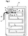
- FIG. 2 shows a second embodiment of an inventive Evaporator board 30, which like the evaporator board 10 is at least one extending approximately meandering over its surface, for example in Rollbond or Z-bond method generated refrigerant channel 31.
- This has an inflow-side arranged in the upper third of the evaporator plate 30 Channel end portion 32, the free end one into a tubular Connecting piece 33 receiving section 34, the connecting piece 33 in the present case is in the form of a circular hollow cylinder.
- the connector 33 has a truncated cone Section 35 on. This is within a drain end section 36 Serving channel piece of the refrigerant channel 31 arranged, which for receiving of the frustoconical section 35 one with its free end Has channel section 32 facing connection piece 37.
- connection section 38 is provided.
- annular connecting element 39 which, on the one hand, seals against the channel wall of the connecting piece 37 or the channel end section 32 and on the other hand sealing to the jacket side of the Connector 33 creates.
- the connector 33 is the smaller one End of its truncated cone-like section 35 having a cross-sectional area with one serving as a throttle and belonging to a capillary tube 40 End portion 41 connected liquid and gas tight, the end portion 41 for Formation of a refrigerant injection point 42 in the frustoconical section 35 protrudes.
- the capillary tube 40 which is inside the drain-side channel end portion 36 is guided from its connecting piece 37 to its connecting section 38, runs outside of the evaporator board 30 within a liquid and gas tight connected to the connection section 38 suction pipe 43, whereby the capillary 40 cooled down to improve the energy efficiency of the refrigerant circuit is.
Landscapes
- Engineering & Computer Science (AREA)
- Physics & Mathematics (AREA)
- Mechanical Engineering (AREA)
- Thermal Sciences (AREA)
- General Engineering & Computer Science (AREA)
- Air-Conditioning For Vehicles (AREA)
- Heat-Exchange Devices With Radiators And Conduit Assemblies (AREA)
- Removal Of Water From Condensation And Defrosting (AREA)
Abstract
Description
- Fig. 1
- eine erste Ausführungsvariante einer erfindungsgemäßen Verdampferplatine mit einem innerhalb einer Aussparung angeordneten Anschlußstück für ein als Drossel dienendes Kapillarrohr, in Ansicht von vorne, und
- Fig. 2
- eine zweite Ausführungvariante einer erfindungsgemäßen Verdampferplatine mit einem elastisch zwischen seinem zuflußseitigen und seinem abflußseitigen Kanalendabschnitts eines Kältemittelkanais eingebundenen Anschlußstückes für das Kapillarrohr, in Ansicht von vorne.
Claims (10)
- Verdampferplatine mit wenigstens einem darauf angeordneten Kältemittelkanal, welcher wenigstens einen an eine Saugleitung angeschlossenen abflußseitigen Kanalendabschnitt und welcher wenigstens einen zuflußseitigen, über ein als Drossel dienendes Kapillarrohr mit Kältemittel beaufschlagbaren Kanalendabschnitt mit einer durch das Kapillarrohr gebildeten Kältemitteleinspritzstelle besitzt, dadurch gekennzeichnet, daß Mittel (16,20; 33, 39) vorgesehen sind, welche die Kältemitteleinspritzstelle (23,42) zumindest weitestgehend körperschallhemmend an die Verdampferplatine (10, 30) anzukoppeln vermögen.
- Verdampferplatine nach Anspruch 1, dadurch gekennzeichnet, daß die Mittel als ein strömungstechnisch dem zuflußseitigen Kanalendabschnitt (32) vorgelagertes, die Kältemitteleinspritzstelle (23,42) aufweisendes rohrähnliches Anschlußstück (33) ausgebildet sind, welches zum Anschluß des Kapillarrohres (40) dient und welches über elastische Verbindungselemente (39) mit dem zuflußseitigen Kanalendabschnitt (32) und dem abflußseitigen Kanalendabschnitt (36) verbunden ist.
- Verdampferplatine nach Anspruch 1, dadurch gekennzeichnet, daß die Mittel als ein strömungstechnisch dem zuflußseitigen Kanalendabschnitt (19) vorgelagertes, von dem abflußseitigen Kanalendabschnitt (12) mechanisch und strömungstechnisch entkoppeltes die Kältemitteleinspritzstelle (23, 42) aufweisendes Anschlußstück (20) ausgebildet sind, an welches das Kapillarrohr (14) angeschlossen ist.
- Verdampferplatine nach einem der Ansprüche 1 bis 3, dadurch gekennzeichnet, daß das rohrähnliche Anschlußstück (20, 33) in einer in die Verdampferplatine (10) eingebrachten Aussparung (16) angeordnet ist.
- Verdampferplatine nach einem der Ansprüche 1 bis 4, dadurch gekennzeichnet, daß der zuflußseitige Kanalendabschnitt (19,32) mit dem daran angeschlossenen Anschlußstück (20,33) zumindest über dessen Anschlußlänge innerhalb der Aussparung (16) angeordnet ist.
- Verdampferplatine nach einem der Ansprüche 1 bis 5, dadurch gekennzeichnet daß das rohrähnliche Anschlußstück (20,33) zumindest einen kegelstumpfähnlich ausgebildeten Längenabschnitt aufweist, an dessen mit geringerer Querschnittsfläche ausgestattetem Ende das Kapillarrohr (14,40) angeschlossen ist.
- Verdampferplatine nach einem der Ansprüche 1 bis 6, dadurch gekennzeichnet, daß das Kapillarrohr (14) außerhalb des abflußseitigen Kanalendabschnittes (12) dem zuflußseitigen Kanalendabachnitt (19) zugeführt und mit diesem strömungstechnisch verbunden ist.
- Verdampferplatine nach einem der Ansprüche 1 bis 7, dadurch gekennzeichnet, daß das Kapillarrohr (14) innerhalb der Saugleitung (13) bis in den Nahbereich des abflußseitigen Kanalendabschnittes (12) verläuft und im Abstand von diesem aus der Saugleitung (13) herausgeführt und an das Anschlußstück (20) angeschlossen ist.
- Verdampferplatine nach einem der Ansprüche 1 bis 7, dadurch gekennzeichnet, daß das Kapillarrohr (14) an der Mantelfläche der Saugleitung (13) entlanggeführt und an das Anschlußstück (20) angeschlossen ist.
- Verdampferplatine nach einem der Ansprüche 1 bis 9, dadurch gekennzeichnet, daß zumindest der innerhalb der Aussparung (16) angeordnete zuflußseitige Kanalendabschnitt (19,32) und das zum Anschluß des Kapillarrohres (14,40) dienende Anschlußstück (20,33) in schalldämmendes Material eingebettet ist.
Priority Applications (1)
| Application Number | Priority Date | Filing Date | Title |
|---|---|---|---|
| SI200030906T SI1030134T1 (sl) | 1999-02-19 | 2000-01-31 | Izparilna plosca |
Applications Claiming Priority (2)
| Application Number | Priority Date | Filing Date | Title |
|---|---|---|---|
| DE19907183 | 1999-02-19 | ||
| DE19907183A DE19907183A1 (de) | 1999-02-19 | 1999-02-19 | Verdampferplatine |
Publications (3)
| Publication Number | Publication Date |
|---|---|
| EP1030134A2 true EP1030134A2 (de) | 2000-08-23 |
| EP1030134A3 EP1030134A3 (de) | 2002-07-10 |
| EP1030134B1 EP1030134B1 (de) | 2006-08-16 |
Family
ID=7898179
Family Applications (1)
| Application Number | Title | Priority Date | Filing Date |
|---|---|---|---|
| EP00101901A Expired - Lifetime EP1030134B1 (de) | 1999-02-19 | 2000-01-31 | Verdampferplatine |
Country Status (4)
| Country | Link |
|---|---|
| EP (1) | EP1030134B1 (de) |
| DE (2) | DE19907183A1 (de) |
| ES (1) | ES2269030T3 (de) |
| SI (1) | SI1030134T1 (de) |
Cited By (4)
| Publication number | Priority date | Publication date | Assignee | Title |
|---|---|---|---|---|
| WO2004023049A1 (de) * | 2002-08-13 | 2004-03-18 | BSH Bosch und Siemens Hausgeräte GmbH | Wärmetauscher-turbine-anordnung |
| EP1477749A1 (de) * | 2003-05-13 | 2004-11-17 | Sergio Daniel Novoa | Wärmetauscheranordnung für Kompressionskältesystem |
| CN102414523A (zh) * | 2009-04-24 | 2012-04-11 | Bsh博世和西门子家用电器有限公司 | 蒸发器以及装备有该蒸发器的致冷设备 |
| RU2516631C2 (ru) * | 2008-11-11 | 2014-05-20 | Бсх Бош Унд Сименс Хаусгерете Гмбх | Сборная конструкция из всасывающей и дроссельной трубок, использующий такую конструкцию испаритель и бытовой холодильный аппарат с такой конструкцией или таким испарителем |
Families Citing this family (2)
| Publication number | Priority date | Publication date | Assignee | Title |
|---|---|---|---|---|
| DE102011078319A1 (de) * | 2011-06-29 | 2013-01-03 | BSH Bosch und Siemens Hausgeräte GmbH | Kältegerät |
| DE102013021350A1 (de) * | 2013-12-04 | 2015-06-11 | Liebherr-Hausgeräte Lienz Gmbh | Kühl- und/oder Gefriergerät |
Family Cites Families (11)
| Publication number | Priority date | Publication date | Assignee | Title |
|---|---|---|---|---|
| US2776550A (en) * | 1952-10-21 | 1957-01-08 | Gen Electric | Capillary adaptor |
| DE973828C (de) * | 1953-10-01 | 1960-06-15 | Gen Motors Corp | Kaelteeinrichtung fuer Kuehlschraenke |
| US2992546A (en) * | 1955-11-14 | 1961-07-18 | Westinghouse Electric Corp | Inlet structure for refrigerant evaporator |
| DE7338368U (de) * | 1972-10-30 | 1974-04-04 | General Motors Corp | Klimagerät, vorzugsweise für Automobile |
| DE2436248A1 (de) * | 1974-07-27 | 1976-02-05 | Bosch Siemens Hausgeraete | Verdampferplatine, insbesondere walzgeschweisste verdampferplatine |
| JPH01181046A (ja) * | 1988-01-12 | 1989-07-19 | Matsushita Seiko Co Ltd | 空気調和機の冷凍サイクルの減圧装置 |
| DE4120651A1 (de) * | 1991-06-22 | 1993-01-14 | Krupp Vdm Ag | Verdampfer fuer ein kompressor-kuehlgeraet |
| DE9217405U1 (de) * | 1992-03-30 | 1993-02-18 | KM-Schmöle GmbH, 5750 Menden | Kälteeinrichtung für Kühlschränke |
| DE4321072A1 (de) * | 1993-06-24 | 1995-01-05 | Bosch Siemens Hausgeraete | Verbindung zwischen zwei Rohren |
| JPH08296924A (ja) * | 1995-04-24 | 1996-11-12 | Matsushita Refrig Co Ltd | 冷凍装置 |
| JPH1078271A (ja) * | 1996-09-04 | 1998-03-24 | Showa Alum Corp | キャピラリチューブの冷媒吐出音防止構造 |
-
1999
- 1999-02-19 DE DE19907183A patent/DE19907183A1/de not_active Withdrawn
-
2000
- 2000-01-31 ES ES00101901T patent/ES2269030T3/es not_active Expired - Lifetime
- 2000-01-31 SI SI200030906T patent/SI1030134T1/sl unknown
- 2000-01-31 EP EP00101901A patent/EP1030134B1/de not_active Expired - Lifetime
- 2000-01-31 DE DE50013313T patent/DE50013313D1/de not_active Expired - Lifetime
Cited By (4)
| Publication number | Priority date | Publication date | Assignee | Title |
|---|---|---|---|---|
| WO2004023049A1 (de) * | 2002-08-13 | 2004-03-18 | BSH Bosch und Siemens Hausgeräte GmbH | Wärmetauscher-turbine-anordnung |
| EP1477749A1 (de) * | 2003-05-13 | 2004-11-17 | Sergio Daniel Novoa | Wärmetauscheranordnung für Kompressionskältesystem |
| RU2516631C2 (ru) * | 2008-11-11 | 2014-05-20 | Бсх Бош Унд Сименс Хаусгерете Гмбх | Сборная конструкция из всасывающей и дроссельной трубок, использующий такую конструкцию испаритель и бытовой холодильный аппарат с такой конструкцией или таким испарителем |
| CN102414523A (zh) * | 2009-04-24 | 2012-04-11 | Bsh博世和西门子家用电器有限公司 | 蒸发器以及装备有该蒸发器的致冷设备 |
Also Published As
| Publication number | Publication date |
|---|---|
| EP1030134A3 (de) | 2002-07-10 |
| ES2269030T3 (es) | 2007-04-01 |
| DE50013313D1 (de) | 2006-09-28 |
| EP1030134B1 (de) | 2006-08-16 |
| DE19907183A1 (de) | 2000-08-24 |
| SI1030134T1 (sl) | 2007-02-28 |
Similar Documents
| Publication | Publication Date | Title |
|---|---|---|
| DE69724050T2 (de) | Elektrisch angetriebener hermetisch gekapselter verdichter | |
| DE19939015B4 (de) | Kompressor mit einem Steuerventil in einem Ansaugdurchgang des Kompressors | |
| DE4344624A1 (de) | Rückschlagventil | |
| DE4007371A1 (de) | Auslassventilanordnung bei einem umlaufkolben-rotationskompressor | |
| WO2005031161A2 (de) | Fluidpumpe, insbesondere kraftstoffhochdruckpumpe, mit druckdämpfer | |
| EP0629824B1 (de) | Verdampfer für ein Kompressor-Kühlgerät | |
| DE10304733A1 (de) | Plattenwärmetauscher | |
| DE19520229A1 (de) | Schalldämpfer für Motorkompressoren von Kühlgeräten | |
| EP1030134B1 (de) | Verdampferplatine | |
| DE20314134U1 (de) | Pneumatischer Abblas-Schalldämpfer | |
| DE102010015147A1 (de) | Ölschwappdämpfungseinrichtung für einen Schraubenverdichter | |
| DE10030435A1 (de) | Geräuschdämpfer für ein Leerlauf-Bypassventil | |
| DE102021110773A1 (de) | Radialverdichter | |
| AT414155B (de) | Brennkraftmaschine mit 2-stufigem abgasturbolader und ladeluftkühlung zwischen nieder- und hochdruckverdichter | |
| DE10065365B4 (de) | Ansaugsystem | |
| EP1176301A2 (de) | Zylinderkurbelgehäuse einer Brennkraftmaschine | |
| DE60200240T2 (de) | Zweitakt-brennkraftmaschine, die eine pneumatisch unterstützte kraftstoffdirekteinspritzung verwendet | |
| EP3848651B1 (de) | Wärmetechnisches gerät | |
| EP2108912A1 (de) | Kondensator, insbesondere für eine Kraftfahrzeug-Klimaanlage | |
| DE102020202088B4 (de) | Linearkompressor | |
| EP1293736A1 (de) | Kältesystem zur Klimatisierung eines Fahrzeuges und Kühleinrichtung zum Einsatz in einem derartigen Kältesystem | |
| DE19757829A1 (de) | Kältemittelkompressor | |
| DE102008058938A1 (de) | Saugrohrsystem für eine Brennkraftmaschine | |
| EP2312148A1 (de) | Hochdruck-Kraftstoffkolbenpumpe | |
| DE69821849T2 (de) | Gegossener Saugeinlass |
Legal Events
| Date | Code | Title | Description |
|---|---|---|---|
| PUAI | Public reference made under article 153(3) epc to a published international application that has entered the european phase |
Free format text: ORIGINAL CODE: 0009012 |
|
| AK | Designated contracting states |
Kind code of ref document: A2 Designated state(s): AT BE CH CY DE DK ES FI FR GB GR IE IT LI LU MC NL PT SE |
|
| AX | Request for extension of the european patent |
Free format text: AL;LT;LV;MK;RO;SI |
|
| RIN1 | Information on inventor provided before grant (corrected) |
Inventor name: HUEBNER, HEINZ Inventor name: HOWE, MICHAEL Inventor name: ARNOLD, FRIEDRICH |
|
| PUAL | Search report despatched |
Free format text: ORIGINAL CODE: 0009013 |
|
| AK | Designated contracting states |
Kind code of ref document: A3 Designated state(s): AT BE CH CY DE DK ES FI FR GB GR IE IT LI LU MC NL PT SE |
|
| AX | Request for extension of the european patent |
Free format text: AL;LT;LV;MK;RO;SI |
|
| 17P | Request for examination filed |
Effective date: 20030110 |
|
| AKX | Designation fees paid |
Designated state(s): DE ES FR GB IT SE |
|
| AXX | Extension fees paid |
Extension state: SI Payment date: 20030110 |
|
| RAP1 | Party data changed (applicant data changed or rights of an application transferred) |
Owner name: BSH BOSCH UND SIEMENS HAUSGERAETE GMBH |
|
| 17Q | First examination report despatched |
Effective date: 20050309 |
|
| GRAP | Despatch of communication of intention to grant a patent |
Free format text: ORIGINAL CODE: EPIDOSNIGR1 |
|
| GRAS | Grant fee paid |
Free format text: ORIGINAL CODE: EPIDOSNIGR3 |
|
| GRAA | (expected) grant |
Free format text: ORIGINAL CODE: 0009210 |
|
| AK | Designated contracting states |
Kind code of ref document: B1 Designated state(s): DE ES FR GB IT SE |
|
| AX | Request for extension of the european patent |
Extension state: SI |
|
| PG25 | Lapsed in a contracting state [announced via postgrant information from national office to epo] |
Ref country code: IT Free format text: LAPSE BECAUSE OF FAILURE TO SUBMIT A TRANSLATION OF THE DESCRIPTION OR TO PAY THE FEE WITHIN THE PRESCRIBED TIME-LIMIT;WARNING: LAPSES OF ITALIAN PATENTS WITH EFFECTIVE DATE BEFORE 2007 MAY HAVE OCCURRED AT ANY TIME BEFORE 2007. THE CORRECT EFFECTIVE DATE MAY BE DIFFERENT FROM THE ONE RECORDED. Effective date: 20060816 |
|
| REG | Reference to a national code |
Ref country code: GB Ref legal event code: FG4D Free format text: NOT ENGLISH |
|
| GBT | Gb: translation of ep patent filed (gb section 77(6)(a)/1977) |
Effective date: 20060904 |
|
| REF | Corresponds to: |
Ref document number: 50013313 Country of ref document: DE Date of ref document: 20060928 Kind code of ref document: P |
|
| REG | Reference to a national code |
Ref country code: SE Ref legal event code: TRGR |
|
| ET | Fr: translation filed | ||
| REG | Reference to a national code |
Ref country code: ES Ref legal event code: FG2A Ref document number: 2269030 Country of ref document: ES Kind code of ref document: T3 |
|
| PLBE | No opposition filed within time limit |
Free format text: ORIGINAL CODE: 0009261 |
|
| STAA | Information on the status of an ep patent application or granted ep patent |
Free format text: STATUS: NO OPPOSITION FILED WITHIN TIME LIMIT |
|
| 26N | No opposition filed |
Effective date: 20070518 |
|
| PGFP | Annual fee paid to national office [announced via postgrant information from national office to epo] |
Ref country code: FR Payment date: 20120201 Year of fee payment: 13 |
|
| PGFP | Annual fee paid to national office [announced via postgrant information from national office to epo] |
Ref country code: GB Payment date: 20120124 Year of fee payment: 13 Ref country code: IT Payment date: 20120126 Year of fee payment: 13 Ref country code: SE Payment date: 20120124 Year of fee payment: 13 |
|
| PGFP | Annual fee paid to national office [announced via postgrant information from national office to epo] |
Ref country code: ES Payment date: 20120124 Year of fee payment: 13 |
|
| GBPC | Gb: european patent ceased through non-payment of renewal fee |
Effective date: 20130131 |
|
| REG | Reference to a national code |
Ref country code: SE Ref legal event code: EUG |
|
| REG | Reference to a national code |
Ref country code: FR Ref legal event code: ST Effective date: 20130930 |
|
| REG | Reference to a national code |
Ref country code: SI Ref legal event code: KO00 Effective date: 20130904 |
|
| PG25 | Lapsed in a contracting state [announced via postgrant information from national office to epo] |
Ref country code: SE Free format text: LAPSE BECAUSE OF NON-PAYMENT OF DUE FEES Effective date: 20130201 |
|
| PG25 | Lapsed in a contracting state [announced via postgrant information from national office to epo] |
Ref country code: FR Free format text: LAPSE BECAUSE OF NON-PAYMENT OF DUE FEES Effective date: 20130131 Ref country code: GB Free format text: LAPSE BECAUSE OF NON-PAYMENT OF DUE FEES Effective date: 20130131 |
|
| PG25 | Lapsed in a contracting state [announced via postgrant information from national office to epo] |
Ref country code: IT Free format text: LAPSE BECAUSE OF NON-PAYMENT OF DUE FEES Effective date: 20130131 |
|
| REG | Reference to a national code |
Ref country code: ES Ref legal event code: FD2A Effective date: 20140321 |
|
| PG25 | Lapsed in a contracting state [announced via postgrant information from national office to epo] |
Ref country code: ES Free format text: LAPSE BECAUSE OF NON-PAYMENT OF DUE FEES Effective date: 20130201 |
|
| REG | Reference to a national code |
Ref country code: DE Ref legal event code: R081 Ref document number: 50013313 Country of ref document: DE Owner name: BSH HAUSGERAETE GMBH, DE Free format text: FORMER OWNER: BSH BOSCH UND SIEMENS HAUSGERAETE GMBH, 81739 MUENCHEN, DE Effective date: 20150402 |
|
| PGFP | Annual fee paid to national office [announced via postgrant information from national office to epo] |
Ref country code: DE Payment date: 20170131 Year of fee payment: 18 |
|
| REG | Reference to a national code |
Ref country code: DE Ref legal event code: R119 Ref document number: 50013313 Country of ref document: DE |
|
| PG25 | Lapsed in a contracting state [announced via postgrant information from national office to epo] |
Ref country code: DE Free format text: LAPSE BECAUSE OF NON-PAYMENT OF DUE FEES Effective date: 20180801 |