EP1029815A1 - Kraftübertragungs- oder Transportvorrichtung - Google Patents
Kraftübertragungs- oder Transportvorrichtung Download PDFInfo
- Publication number
- EP1029815A1 EP1029815A1 EP00810078A EP00810078A EP1029815A1 EP 1029815 A1 EP1029815 A1 EP 1029815A1 EP 00810078 A EP00810078 A EP 00810078A EP 00810078 A EP00810078 A EP 00810078A EP 1029815 A1 EP1029815 A1 EP 1029815A1
- Authority
- EP
- European Patent Office
- Prior art keywords
- drive
- elements
- force
- power transmission
- tensioning
- Prior art date
- Legal status (The legal status is an assumption and is not a legal conclusion. Google has not performed a legal analysis and makes no representation as to the accuracy of the status listed.)
- Granted
Links
- 230000005540 biological transmission Effects 0.000 title claims abstract description 39
- 230000008878 coupling Effects 0.000 claims description 9
- 238000010168 coupling process Methods 0.000 claims description 9
- 238000005859 coupling reaction Methods 0.000 claims description 9
- 230000002093 peripheral effect Effects 0.000 claims 3
- 238000010516 chain-walking reaction Methods 0.000 description 1
Images



Classifications
-
- B—PERFORMING OPERATIONS; TRANSPORTING
- B65—CONVEYING; PACKING; STORING; HANDLING THIN OR FILAMENTARY MATERIAL
- B65G—TRANSPORT OR STORAGE DEVICES, e.g. CONVEYORS FOR LOADING OR TIPPING, SHOP CONVEYOR SYSTEMS OR PNEUMATIC TUBE CONVEYORS
- B65G35/00—Mechanical conveyors not otherwise provided for
- B65G35/06—Mechanical conveyors not otherwise provided for comprising a load-carrier moving along a path, e.g. a closed path, and adapted to be engaged by any one of a series of traction elements spaced along the path
-
- B—PERFORMING OPERATIONS; TRANSPORTING
- B65—CONVEYING; PACKING; STORING; HANDLING THIN OR FILAMENTARY MATERIAL
- B65G—TRANSPORT OR STORAGE DEVICES, e.g. CONVEYORS FOR LOADING OR TIPPING, SHOP CONVEYOR SYSTEMS OR PNEUMATIC TUBE CONVEYORS
- B65G23/00—Driving gear for endless conveyors; Belt- or chain-tensioning arrangements
- B65G23/32—Driving gear for endless conveyors; Belt- or chain-tensioning arrangements for effecting drive at two or more points spaced along the length of the conveyors
Definitions
- the invention relates to a power transmission or transport device according to the preamble of the first independent claim.
- the device has as the power transmission means a number of power transmission Elements, guide means for guiding the force-transmitting elements along a predetermined path and at least one drive, wherein the drive acts locally on force-transmitting elements and these in the drive area moved on the given path and being driven Move elements by pushing or pulling further elements in the row.
- the force transmitting elements can be linked together to form a chain, e.g. to be connected in a self-contained chain, the connections have more or less play between the elements. Connected force-transmitting elements can interact with each other or if they have suitable shapes and suitable guide means are provided become thrusting too.
- the force-transmitting elements can but also be disconnected. For unconnected, force-transmitting elements are guide means for the entire specified path (e.g. Guide channel or rails) and it is only a power transmission possible by poking.
- the power transmission elements are at least partially for transport purposes equipped with means of transport or connectable to them.
- the means of transport are, for example, grippers for individual objects or loading areas or container, through the force-transmitting elements along the given path.
- Drives for the power transmission means mentioned above are for example Sprockets that are in the power transmission elements or between the power transmission Intervene elements (form-locking) and these mostly Take along an arcuate path. Even drives that have the elements Driving via friction locking is possible.
- On loaded sections of the track e.g. between an input and an output
- rows of pushed elements Elements smallest distances. They are on unloaded sections of track Distances are not precisely defined and may vary external circumstances.
- Chain tensioners are used to tension chains, for example in Form of spring-loaded, passively rotating chain wheels with the chain known or chain channels that are elastically deformable in the longitudinal direction and are designed a little longer than the chain running in it.
- Such a bias between the power transmission means (chain) and Guide means (chain tensioner or longitudinally elastic channel) is only possible for a power transmission means that is essentially seamless over a self-contained, predetermined path extends. It is not applicable to a power transmission means with two ends on a given Web is moved back and forth, it is not applicable to rows of not interconnected, force-transmitting elements that vary Number can be moved on a given path and it is not applicable for only a local pre-tensioning of the power transmission means.
- the invention now has the task of a power transmission or Transport device with a number of interconnected or non-interconnected, force-transmitting elements as force transmission means, with at least one locally on force-transmitting elements acting drive and with guide means for guiding the power-transmitting To create elements on a predetermined path, the inventive The device is intended to make it possible to transfer the series of power Elements on at least a section of the specified path to tension and thereby precisely defined element distances on this section adjust. In particular, this should be possible regardless of whether the elements are connected or not and regardless of whether the predetermined path and / or the series of force-transmitting elements is closed or not.
- the device according to the invention has means by means of which the Row of force-transmitting elements on a given section the specified path tensioned by a tensile or compressive stress becomes, in such a way that the largest possible possible between connected elements Distance (tension) or between connected or unconnected The smallest possible distance (compressive stress).
- the tension drive tension
- v against it driven
- the voltage that can be generated between the tension drive and another drive or stop corresponds to the frictional resistance of the friction clutch of the tension drive.
- the further drive or stop acts essentially without slip on power transmission Elements, that means, for example, positive or frictional in such a way that the further drive only slips when it is significant higher forces occur than with the tension drive.
- Figures 1 and 2 show very schematically illustrated sections of exemplary embodiments of the device according to the invention the principle of operation of this device.
- Figure 1 shows a guide means 1 in the form of a guide channel or corresponding rails (shown schematically by two lines).
- a predetermined path is defined by the guide means, on which a row of force-transmitting elements 2 (not connected to one another in the case shown) can be displaced.
- the force-transmitting elements 2 have a type of toothing on one side, in which a drive 3 in the form of a gearwheel 4 engages in a form-fitting manner, as a result of which the force-transmitting elements 2 are displaced in the guide means 1 at a drive speed v.
- the drive 3 represents the one end of a section 5 of the predetermined path on which a compressive stress is to be generated in the row of the force-transmitting elements 2.
- a tensioning drive 6 is arranged at the other end of this section 5.
- This consists of a tensioning wheel 7, which carries on its circumference a ring 8 made of an elastically deformable material and which is pressed against the force-transmitting elements 2 by means not shown.
- the tensioning wheel 7 is driven via coupling means 12 (eg toothed belt) and by the drive 3, in such a way that the drive speed v s with which the tensioning wheel 7 drives the elements 2 is greater than the drive speed v with which the drive 3 drives the drives force-transmitting elements 2 (resulting speed v s - v is directed from the tensioning drive 6 into the section 5).
- tensioning drive 6 By means of the tensioning drive 6, a number of mutually opposing parts 5 is formed pressed and force-transmitting elements 2 created and maintained, in which row the distances between the elements are the smallest possible and are therefore precisely defined.
- the frictional force between elements 2 and tension wheel 7 is set such that the tension wheel 7 on the Elements 2 slips when a desired tension in the series of elements 2 between the drive 3 and the tensioning drive 6 is reached.
- the drive 3 can be a continuous drive (gear 4 continuous rotating) or he can gradually move the elements 2 that means driving and stopping intermittently.
- the tensioning drive 6 is advantageously in all cases a continuous drive and in the case of a gradual drive 3 is not coupled with this.
- the elements 2 will be with active stop 9 (in engagement with the elements) by the tension drive 6 stretched in a row between stop 9 and tension drive 6 and at inactive stop 8 (stop with the elements not engaged) by the Tension drive 6 pushed further.
- compressive stress is applied to section 5 and thereby creates a defined distance between the elements for example, a clean engagement of the drive 3 in the elements 2 to ensure.
- the device according to FIG. 1 can also be operated in a direction which is opposite to the illustrated direction of the drive speed v.
- the driving speed s v of the tensioning drive 6 is smaller than V or opposite to v directed (resultant velocity v s - v from the tensioning drive 6 in the portion 5 facing) to be selected in such a way that the elements are braked by the tensioning drive.
- FIG. 2 shows, in the same representation as FIG. 1, a force transmission or transport device in which a tensile stress is generated via a section 5 in a row of force-transmitting elements 2 connected to one another via flexible connections 10.
- This tension by means of which the maximum possible and therefore precisely defined distances between the force-transmitting elements 2 are set on the section 5, is generated by a tensioning drive 6 and a further drive 3, the drive speed v s of the tensioning drive 6 being lower than the drive speed v of the drive 3 or directed against it (resulting speed v s - v pointing away from the clamping drive 6 from the section 5).
- the apparatus according to Figure 2 can be operated in the opposite direction (v leftward), the driving velocity v s has to be greater than V (resulting velocity s v - v from the clamping drive from the portion 5 facing away).
- the drive 3 of the device according to FIG. 2 is, like in FIG. 1, a chain or gear wheel 4.
- the tensioning drive 6 also has a chain or Gear 11, which engages positively in the chain of elements 2.
- the Sprocket 11 of the tensioning drive 6 is via coupling means 12 with the Drive 3 coupled which coupling means 12 a friction clutch (e.g. Represent clutch belt) and is designed so that the clutch begins to slip, wine in the series of force-transmitting elements desired voltage is generated.
- a friction clutch e.g. Represent clutch belt
- FIGs 3 and 4 show an exemplary embodiment of a tensioning drive 6 for a power transmission or transport device according to the invention as a side view ( Figure 3) and as a plan view from below ( Figure 4, viewing direction according to arrow IV in Figure 3).
- the tensioning drive 6 has a tensioning wheel 20 which is frictionally connected to the force-transmitting elements 2 and has an elastically deformable circumferential tire 21 driven by a pair of driven wheels 22, which are also frictionally connected to the force-transmitting elements 2 and whose elastically deformable circumferential tires 23 also serve as belts between the driven wheels 22 and the tensioning wheel 20.
- the belt drive which serves as a coupling between the driven wheels 22 and the tensioning wheel 20 is designed for the desired translation of the tensioning wheel 20 relative to the driven wheels 22, in the present case such that the drive speed v s is greater than the drive speed v '.
- the driven wheels 22 are freely rotatably mounted in first press levers 27 in turn are pivotally mounted in fixed supports 28 and by the first spring means 25 against the guide means 1 or against the guide means guided, force-transmitting elements 2 are pressed, that is, through which the driven wheels 22 are pressed against the force-transmitting elements 2 and be driven by it.
- the tensioning wheel 20 is freely rotatable in second press levers 29, which second press lever 29 via second spring means 26 on the first press levers 27 are attached.
- the second spring means 26 press the second press lever 29 and thus the tensioning wheel 20 against the force-transmitting elements 2 and are designed in such a way that the resulting press force is less than that on the output wheels 22 acting press force.
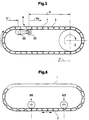
- FIG. 5 shows an exemplary embodiment of a device according to the invention with a tensioning drive according to FIGS. 3 and 4.
- the guide means 1 of the device define a self-contained path in which, for example, force-transmitting elements 2 that are not connected to one another are displaced clockwise by a drive 3.
- the guide means 1 is somewhat longer than the row of force-transmitting elements 2.
- the device additionally has a tensioning drive 6, from the way it was described in connection with Figures 3 and 4.
- the tensioning drive 6 has an output gear 22 and one through the output gear driven tensioning wheel 20.
- the tensioning wheel 20 between drive 3 and tensioning wheel 20 (section 5) a compressive stress on the series of elements 2 generated.
- a tension on this part of the specified path in this case also a compressive stress, the size of which depends on the braking of the Elements through the downforce 22.
- the distances between the power transmitting Elements 2 are the smallest possible, except for the route between driven wheel 22 and tensioning wheel 20 of the tensioning drive 6, where the distances or the distance of the total longitudinal play of the power transmission means corresponds.
- this Total play in the row of pressure-transmitting elements 2 is not greater is the distance between driven gear 22 and idler gear 20.
- the compressive stresses that can be generated in the device according to FIG. 5 are for section 5 depending on the frictional force between tensioning wheel 20 and force-transmitting elements 2 and for the section between drive 3 and driven wheel 22 depending on the braking of the elements 2 by the Output gear 22, for example very small.
- FIG. 6 shows a device according to the invention with a guide means 1 that defines a self-contained path on which a non-endless chain of interconnected, force-transmitting elements 2 can be displaced in both directions.
- the device also has two spaced drives 3/6 and 6/3, of which one is always operatively connected to the elements 2 as a drive 3 essentially without slippage and the other as a tension drive 6 via a friction clutch.
- a tensile stress or a compressive stress is generated in the chain of force-transmitting elements in the web area between the drives, thereby creating the greatest possible or the smallest possible distance between the chain links.
- FIG. 6 What is shown in FIG. 6 on a self-contained path is of course also possible with a non-self-contained path, as is shown in FIG. 7 with a chain of force-transmitting elements 2 stretched between the drives 6/3 and 3/6 is shown.
- FIGS. 8 and 9 show a further exemplary embodiment of the device according to the invention.
- the device is shown in FIG. 9 as a top view and in part in FIG. 8 as a side view.
- the force-transmitting elements 2 are not connected to one another and can be pushed in a row in an abutting manner between rails, not shown.
- the device has two essentially identical drives 3 and 6, both of which have a toothed belt 32 running over two toothed wheels 30 and 31 (the corresponding axes are shown in FIG. 9), which engages in a form-fitting manner in corresponding toothings of the elements 2.
- the gearwheel 30 of the drive 3 shown above in FIG. 9 is operatively connected to a motor M essentially without slip.
- the gearwheel 30 of the tensioning drive 6 shown below in FIG. 9 is connected to the driven shaft of the drive 3 via a pair of friction wheels 33, the pair of friction wheels 33 being dimensioned such that it represents a friction clutch and a reduction.
- the elements 2 are driven by the drive 3 moved against the tensioning drive 6 and braked by the tensioning drive 6 in such a way that are in the series of force-transmitting elements 2 between the drive 3 and tension drive 6 forms a compressive stress through which the distances between the elements 2 are kept to a minimum.
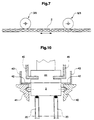
- FIG. 10 shows such an element 2 in a section across the predetermined path to illustrate the use of defined distances set between force-transmitting elements.
- This predetermined path is defined by two rails 40 and 41 (guide means) in which the element 2 slides or rolls.
- a pair of tensioning wheels 20 which, as described in connection with FIGS. 1 to 4, are operatively connected to the element 2 by friction.
- At least the upper surface of the element 2 is magnetizable, for example via the contacts 42, which are in the region of the web shown on rails 43 slide along.
- a transport means 44 is located above the element 2 positioned, which in turn is based on a number of the same means of transport Rails 45 is displaceable and that with the force-transmitting element 2 is magnetically coupled.
- the predetermined path of the power transmission or Transport device can run anywhere in the room and it can too be branched. Furthermore, it can be the same or different in different places Have tension drives.
Landscapes
- Engineering & Computer Science (AREA)
- Mechanical Engineering (AREA)
- Devices For Conveying Motion By Means Of Endless Flexible Members (AREA)
- Transmission Devices (AREA)
- General Details Of Gearings (AREA)
- Special Conveying (AREA)
Abstract
Description
- Figuren 1 und 2
- das Prinzip der erfindungsgemässen Kraftübertragungs- oder Transportvorrichtung, in der im Kraftübertragungsmittel örtlich eine Druckspannung (Figur 1) oder eine Zugspannung (Figur 2) zwischen kraftübertragenden Elementen erzeugbar ist;
- Figuren 3 und 4
- eine beispielhafte Ausführungsform eines Spannantriebs für eine erfindungsgemässe Vorrichtung als Seitenansicht (Figur 3) und als Draufsicht (Figur 4, Blickrichtung Pfeil IV in Figur 3);
- Figuren 5 bis 7
- drei beispielhafte Anwendungen der erfindungsgemässen Vorrichtung;
- Figuren 8 und 9
- eine weitere, beispielhafte Ausführungsform der erfindungsgemässen Vorrichtung als Draufsicht (Figur 9) und als Seitenansicht (Figur 8);
- Figur 10
- eine beispielhafte Anordnung von kraftübertragendem Element und daran ankoppelbarem Transportmittel im Schnitt senkrecht zur vorgegebenen Bahn zur Illustration einer Anwendung der in der erfindungsgemässen Vorrichtung erstellten definierten Abstände zwischen kraftübertragenden Elementen.
Claims (12)
- Kraftübertragungs- oder Transportvorrichtung, welche Vorrichtung eine Reihe von kraftübertragenden Elementen (2), Führungsmittel (1) zur Führung der kraftübertragenden Elemente (2) auf einer vorgegebenen Bahn und mindestens einen Antrieb aufweist, wobei der mindestens eine Antrieb an einer Stelle der vorgegebenen Bahn kraftübertragende Elemente (2) aktiv auf der Bahn bewegt und wobei durch den Antrieb bewegte Elemente (2) weitere Elemente (2) ziehend oder schiebend bewegen, dadurch gekennzeichnet, dass zur Erzeugung einer Spannung auf die Reihe von kraftübertragenden Elementen (2) über ein Teilstück (5) der vorgegebenen Bahn am einen Ende des Teilstücks (5) ein über eine Reibungskupplung auf die Elemente (2) wirkender Spannantrieb (6) und am anderen Ende des Teilstücks (5) ein im wesentlichen schlupffrei auf die Elemente (2) wirkender, weiterer Antrieb (3) oder intermittierender Stopp (9) angeordnet ist, wobei die Antriebsgeschwindigkeit (vs) des Spannantriebs (6) von der Antriebsgeschwindigkeit (v) des weiteren Antriebs (3) oder Stopps (9) verschieden ist.
- Kraftübertragungs- oder Transportvorrichtung nach Anspruch 1, dadurch gekennzeichnet, dass die kraftübertragenden Elemente (2) miteinander verbunden sind und dass der Spannantrieb (6) derart ausgestaltet und positioniert ist, dass er auf dem Teilstück (5) der vorgegebenen Bahn eine Zugspannung oder eine Druckspannung auf die Reihe von Elementen (2) erzeugt.
- Kraftübertragungs- oder Transportvorrichtung nach Anspruch 1, dadurch gekennzeichnet, dass die kraftübertragenden Elemente (2) unverbunden sind und dass der Spannantrieb (6) derart ausgestaltet und positioniert ist, dass er auf dem Teilstück (5) der vorgegebenen Bahn eine Druckspannung auf die Reihe von Elementen (2) erzeugt.
- Kraftübertragungs- oder Transportvorrichtung nach einem der Ansprüche 1 bis 3, dadurch gekennzeichnet, dass der Spannantrieb (6) reibschlüssig mit kraftübertragenden Elementen (2) wirkverbindbar ist.
- Kraftübertragungs- oder Transportvorrichtung nach Anspruch 4, dadurch gekennzeichnet, dass der Spannantrieb (6) ein gegen kraftübertragende Elemente (2) pressbares Spannrad (7, 20) aufweist.
- Kraftübertragungs- oder Transportvorrichtung nach Anspruch 5, dadurch gekennzeichnet, dass das Spannrad (7, 20) einen elastisch deformierbaren Umfangsring (8, 21) aufweist.
- Kraftübertragungs- oder Transportvorrichtung nach einem der Ansprüche 1 bis 3, dadurch gekennzeichnet, dass ein Element (11, 30) des Spannantriebs (6) formschlüssig mit kraftübertragenden Elementen (2) wirkverbindbar ist und dass zwischen zwei Elementen des Spannantriebs (6) eine Reibungskupplung (12, 23, 33) vorgesehen ist.
- Kraftübertragungs- oder Transportvorrichtung nach Anspruch 7, dadurch gekennzeichnet, dass die Reibungskupplung ein Riementrieb (12, 23) oder ein Reibradpaar (33) ist.
- Kraftübertragungs- oder Transportvorrichtung nach einem der Ansprüche 1 bis 8, dadurch gekennzeichnet, dass eine Kupplung zwischen dem Spannantrieb (6) und dem weiteren Antrieb (3) vorgesehen ist.
- Krafrübertragung- oder Transportvorrichtung nach einem der Ansprüche 1 bis 8, dadurch gekennzeichnet, dass der Spannantrieb (6) einen durch kraftübertragende Elemente (2) angetriebenen Abtrieb (22/23) aufweist.
- Kraftübertragungs- oder Transportvorrichtung nach Anspruch 10, dadurch gekennzeichnet, dass der Abtrieb ein Abtriebsrad (22) mit einem elastisch deformierbaren Umfangsring (23) ist und dass der Umfangsring auch als Riemen zur Kupplung zu einem Spannrad (20) dient.
- Kraftübertragungs- oder Transportvorrichtung nach Anspruch 10 oder 11, dadurch gekennzeichnet, dass das Abtriebsrad (22) frei drehbar in ersten Presshebeln (27) und das Spannrad (20) frei drehbar in zweiten Presshebeln (29) gelagert ist, wobei die ersten Presshebel (27) mit ersten Federmitteln (25) gegen die kraftübertragenden Elemente (2) gepresst werden und die zweiten Presshebel (29) über zweite Federmittel (26) an den ersten Presshebeln (27) befestigt sind.
Applications Claiming Priority (2)
| Application Number | Priority Date | Filing Date | Title |
|---|---|---|---|
| CH29099 | 1999-02-16 | ||
| CH29099 | 1999-02-16 |
Publications (2)
| Publication Number | Publication Date |
|---|---|
| EP1029815A1 true EP1029815A1 (de) | 2000-08-23 |
| EP1029815B1 EP1029815B1 (de) | 2004-04-07 |
Family
ID=4183629
Family Applications (1)
| Application Number | Title | Priority Date | Filing Date |
|---|---|---|---|
| EP00810078A Expired - Lifetime EP1029815B1 (de) | 1999-02-16 | 2000-01-28 | Kraftübertragungs- oder Transportvorrichtung |
Country Status (5)
| Country | Link |
|---|---|
| US (1) | US6269942B1 (de) |
| EP (1) | EP1029815B1 (de) |
| AT (1) | ATE263724T1 (de) |
| CA (1) | CA2298397C (de) |
| DE (1) | DE50005949D1 (de) |
Cited By (5)
| Publication number | Priority date | Publication date | Assignee | Title |
|---|---|---|---|---|
| EP1116674A1 (de) * | 2000-01-17 | 2001-07-18 | Sumitomo Wiring Systems, Ltd. | Wagen für ein endloses Förderband und ein transportmechanismus für solch einen Wagen |
| US8627943B2 (en) | 2009-11-18 | 2014-01-14 | Mueller Martini Holding Ag | Guide arrangement for use with a transport member |
| CN104210816A (zh) * | 2013-05-31 | 2014-12-17 | 米勒·马蒂尼控股公司 | 用于传输机构的使用的输送设备 |
| AT510754A3 (de) * | 2010-11-30 | 2015-05-15 | SSI Schäfer PEEM GmbH | Hängeförderer und antriebskette für den hängeförderer |
| US9126813B2 (en) | 2011-05-25 | 2015-09-08 | Hamba Filltec Gmbh & Co. Kg | Container filling device |
Families Citing this family (4)
| Publication number | Priority date | Publication date | Assignee | Title |
|---|---|---|---|---|
| DE10328545B4 (de) * | 2003-06-24 | 2008-08-21 | Sig Technology Ltd. | Vorrichtung und Verfahren zum Betreiben von kontinuierlich auf Trägerelementen bereitgestellten Packungen |
| EP1725482B1 (de) * | 2004-03-18 | 2012-08-15 | WRH Walter Reist Holding AG | Rollende fördervorrichtung |
| DE102007024446A1 (de) * | 2007-05-25 | 2008-11-27 | Groninger & Co. Gmbh | Vorrichtung zum Transport von Behältnissen zu mindestens einer Bearbeitungsstation |
| DE102017118357A1 (de) * | 2017-08-11 | 2019-02-14 | Weiss Gmbh | Transportvorrichtung |
Citations (7)
| Publication number | Priority date | Publication date | Assignee | Title |
|---|---|---|---|---|
| US3059489A (en) * | 1960-10-07 | 1962-10-23 | Gourley Norman | Power transmitting apparatus |
| US4072228A (en) * | 1975-05-20 | 1978-02-07 | Ferag Ag | Apparatus for evening an imbricated stream of printed products |
| US4080841A (en) * | 1975-10-09 | 1978-03-28 | Van Doorne's Transmissle B.V. | Push element for transmission belt |
| EP0309702A1 (de) * | 1987-10-02 | 1989-04-05 | Ferag AG | Endlos umlaufende Stückgut-Transportvorrichtung |
| GB2228910A (en) * | 1989-03-08 | 1990-09-12 | British Res Agricult Eng | Increasing the spacing between receptacles of an endless conveyor |
| US5503264A (en) * | 1993-07-07 | 1996-04-02 | Ferag Ag | Endlessly circulating items transporting apparatus with individual transporting members |
| WO1997015514A1 (en) * | 1995-10-26 | 1997-05-01 | Ebm Techniek B.V. | Apparatus and method for temporarily storing or buffering of products |
Family Cites Families (3)
| Publication number | Priority date | Publication date | Assignee | Title |
|---|---|---|---|---|
| US2519179A (en) * | 1947-06-19 | 1950-08-15 | William M Duncan | Sintering machine |
| CA2266443A1 (en) * | 1996-09-25 | 1998-04-02 | Ipt Weinfelden Ag | Power transmission device for transmitting thrusting force |
| US6019214A (en) * | 1997-03-04 | 2000-02-01 | Atlas Technologies, Inc. | Asynchronous conveyor construction |
-
2000
- 2000-01-28 DE DE50005949T patent/DE50005949D1/de not_active Expired - Lifetime
- 2000-01-28 AT AT00810078T patent/ATE263724T1/de not_active IP Right Cessation
- 2000-01-28 EP EP00810078A patent/EP1029815B1/de not_active Expired - Lifetime
- 2000-02-11 US US09/502,739 patent/US6269942B1/en not_active Expired - Fee Related
- 2000-02-14 CA CA002298397A patent/CA2298397C/en not_active Expired - Fee Related
Patent Citations (7)
| Publication number | Priority date | Publication date | Assignee | Title |
|---|---|---|---|---|
| US3059489A (en) * | 1960-10-07 | 1962-10-23 | Gourley Norman | Power transmitting apparatus |
| US4072228A (en) * | 1975-05-20 | 1978-02-07 | Ferag Ag | Apparatus for evening an imbricated stream of printed products |
| US4080841A (en) * | 1975-10-09 | 1978-03-28 | Van Doorne's Transmissle B.V. | Push element for transmission belt |
| EP0309702A1 (de) * | 1987-10-02 | 1989-04-05 | Ferag AG | Endlos umlaufende Stückgut-Transportvorrichtung |
| GB2228910A (en) * | 1989-03-08 | 1990-09-12 | British Res Agricult Eng | Increasing the spacing between receptacles of an endless conveyor |
| US5503264A (en) * | 1993-07-07 | 1996-04-02 | Ferag Ag | Endlessly circulating items transporting apparatus with individual transporting members |
| WO1997015514A1 (en) * | 1995-10-26 | 1997-05-01 | Ebm Techniek B.V. | Apparatus and method for temporarily storing or buffering of products |
Cited By (10)
| Publication number | Priority date | Publication date | Assignee | Title |
|---|---|---|---|---|
| EP1116674A1 (de) * | 2000-01-17 | 2001-07-18 | Sumitomo Wiring Systems, Ltd. | Wagen für ein endloses Förderband und ein transportmechanismus für solch einen Wagen |
| US6502691B2 (en) | 2000-01-17 | 2003-01-07 | Isamu Akatsuka | Carriage for an endless conveyor and a conveying mechanism for such a carriage |
| US8627943B2 (en) | 2009-11-18 | 2014-01-14 | Mueller Martini Holding Ag | Guide arrangement for use with a transport member |
| AT510754A3 (de) * | 2010-11-30 | 2015-05-15 | SSI Schäfer PEEM GmbH | Hängeförderer und antriebskette für den hängeförderer |
| AT510754B1 (de) * | 2010-11-30 | 2015-12-15 | SSI Schäfer PEEM GmbH | Hängeförderer und antriebskette für den hängeförderer |
| US9126813B2 (en) | 2011-05-25 | 2015-09-08 | Hamba Filltec Gmbh & Co. Kg | Container filling device |
| CN104210816A (zh) * | 2013-05-31 | 2014-12-17 | 米勒·马蒂尼控股公司 | 用于传输机构的使用的输送设备 |
| EP2876062A1 (de) | 2013-05-31 | 2015-05-27 | Müller Martini Holding AG | Fördereinrichtung für den Einsatz eines Transportorgans |
| US9290328B2 (en) | 2013-05-31 | 2016-03-22 | Mueller Martini Holding Ag | Conveying arrangement for use with a transport member |
| CN104210816B (zh) * | 2013-05-31 | 2019-11-12 | 米勒·马蒂尼控股公司 | 用于传输机构的使用的输送设备 |
Also Published As
| Publication number | Publication date |
|---|---|
| EP1029815B1 (de) | 2004-04-07 |
| CA2298397C (en) | 2008-03-25 |
| CA2298397A1 (en) | 2000-08-16 |
| DE50005949D1 (de) | 2004-05-13 |
| US6269942B1 (en) | 2001-08-07 |
| ATE263724T1 (de) | 2004-04-15 |
Similar Documents
| Publication | Publication Date | Title |
|---|---|---|
| DE69230831T3 (de) | Setzgeräte und klebeband dafür | |
| DE60118948T2 (de) | Überführung von gegenständen zwischen entgegengesetzt angetriebenen förderern | |
| DE69927067T2 (de) | Antriebseinheit für fördermotor und fördersystem | |
| EP0276409A2 (de) | Taktförderer | |
| EP0564901B1 (de) | Vorschubeinrichtung für Tafeln | |
| DE102008021506A1 (de) | Vorrichtung zum Querrecken von Folienbahnen | |
| EP1029815B1 (de) | Kraftübertragungs- oder Transportvorrichtung | |
| DE19915271A1 (de) | Fördereinrichtung für Gegenstände in Verpackungsmaschinen | |
| EP1375390A2 (de) | Vorrichtung zur Förderung von Stückgütern | |
| EP0249839A2 (de) | Seilförderanlage, insbesondere Seilschwebebahn | |
| DE3107063A1 (de) | Bandvorschub- und spannmechanismus in einer umschnuerungsvorrichtung | |
| DE3029620A1 (de) | Transporteinrichtung fuer werkstuecktraeger | |
| EP3529180A1 (de) | Fördersystem | |
| EP1330406A1 (de) | Vorrichtung zum verarbeiten von flächigen gegenständen, insbesondere druckereiprodukten | |
| CH421487A (de) | Vorrichtung zur Behandlung fortlaufender Folienbahnen mit Randwülsten im gespannten Zustand | |
| EP1044108B1 (de) | Vorrichtung zum einziehen einer warenbahn | |
| DE10032189B4 (de) | Förderstrecke für Stückgut, insbesondere Werkstückträger | |
| EP0363939B1 (de) | Getriebe zum Umsetzen einer translatorischen Bewegung in eine Drehbewegung und umgekehrt | |
| DE19609145A1 (de) | Einrichtung zum automatischen und/oder manuellen Werkzeugwechsel | |
| DE60309133T2 (de) | Vorrichtung zur anpassung des abstandes zwischen förderfingern an die länge des produktes | |
| EP0936161B1 (de) | Vorrichtung zum Antreiben von Körpern entlang einer vorgegebenen Strecke | |
| DE102024124039B3 (de) | Rollenbahn zum Fördern von Fördergut sowie Verfahren zum Betrieb der Rollenbahn | |
| EP2499070B1 (de) | Fördereinrichtung | |
| DE102024124038B3 (de) | Rollenbahn zum Fördern von Fördergut sowie Verfahren zum Betrieb der Rollenbahn | |
| DE69612932T2 (de) | Antrieb eines Seilförderers für freifliessende, lose Materialien |
Legal Events
| Date | Code | Title | Description |
|---|---|---|---|
| PUAI | Public reference made under article 153(3) epc to a published international application that has entered the european phase |
Free format text: ORIGINAL CODE: 0009012 |
|
| AK | Designated contracting states |
Kind code of ref document: A1 Designated state(s): AT BE CH CY DE DK ES FI FR GB GR IE IT LI LU MC NL PT SE |
|
| AX | Request for extension of the european patent |
Free format text: AL;LT;LV;MK;RO;SI |
|
| 17P | Request for examination filed |
Effective date: 20010127 |
|
| AKX | Designation fees paid |
Free format text: AT BE CH CY DE DK ES FI FR GB GR IE IT LI LU MC NL PT SE |
|
| 17Q | First examination report despatched |
Effective date: 20020912 |
|
| GRAP | Despatch of communication of intention to grant a patent |
Free format text: ORIGINAL CODE: EPIDOSNIGR1 |
|
| GRAS | Grant fee paid |
Free format text: ORIGINAL CODE: EPIDOSNIGR3 |
|
| GRAA | (expected) grant |
Free format text: ORIGINAL CODE: 0009210 |
|
| AK | Designated contracting states |
Kind code of ref document: B1 Designated state(s): AT BE CH CY DE DK ES FI FR GB GR IE IT LI LU MC NL PT SE |
|
| PG25 | Lapsed in a contracting state [announced via postgrant information from national office to epo] |
Ref country code: FI Free format text: LAPSE BECAUSE OF FAILURE TO SUBMIT A TRANSLATION OF THE DESCRIPTION OR TO PAY THE FEE WITHIN THE PRESCRIBED TIME-LIMIT Effective date: 20040407 Ref country code: NL Free format text: LAPSE BECAUSE OF FAILURE TO SUBMIT A TRANSLATION OF THE DESCRIPTION OR TO PAY THE FEE WITHIN THE PRESCRIBED TIME-LIMIT Effective date: 20040407 Ref country code: IE Free format text: LAPSE BECAUSE OF FAILURE TO SUBMIT A TRANSLATION OF THE DESCRIPTION OR TO PAY THE FEE WITHIN THE PRESCRIBED TIME-LIMIT Effective date: 20040407 Ref country code: IT Free format text: LAPSE BECAUSE OF FAILURE TO SUBMIT A TRANSLATION OF THE DESCRIPTION OR TO PAY THE FEE WITHIN THE PRESCRIBED TIME-LIMIT;WARNING: LAPSES OF ITALIAN PATENTS WITH EFFECTIVE DATE BEFORE 2007 MAY HAVE OCCURRED AT ANY TIME BEFORE 2007. THE CORRECT EFFECTIVE DATE MAY BE DIFFERENT FROM THE ONE RECORDED. Effective date: 20040407 Ref country code: FR Free format text: LAPSE BECAUSE OF FAILURE TO SUBMIT A TRANSLATION OF THE DESCRIPTION OR TO PAY THE FEE WITHIN THE PRESCRIBED TIME-LIMIT Effective date: 20040407 |
|
| REG | Reference to a national code |
Ref country code: GB Ref legal event code: FG4D Free format text: NOT ENGLISH |
|
| REG | Reference to a national code |
Ref country code: CH Ref legal event code: EP |
|
| REF | Corresponds to: |
Ref document number: 50005949 Country of ref document: DE Date of ref document: 20040513 Kind code of ref document: P |
|
| REG | Reference to a national code |
Ref country code: CH Ref legal event code: NV Representative=s name: FREI PATENTANWALTSBUERO |
|
| REG | Reference to a national code |
Ref country code: IE Ref legal event code: FG4D Free format text: GERMAN |
|
| GBT | Gb: translation of ep patent filed (gb section 77(6)(a)/1977) |
Effective date: 20040514 |
|
| PG25 | Lapsed in a contracting state [announced via postgrant information from national office to epo] |
Ref country code: DK Free format text: LAPSE BECAUSE OF FAILURE TO SUBMIT A TRANSLATION OF THE DESCRIPTION OR TO PAY THE FEE WITHIN THE PRESCRIBED TIME-LIMIT Effective date: 20040707 Ref country code: GR Free format text: LAPSE BECAUSE OF FAILURE TO SUBMIT A TRANSLATION OF THE DESCRIPTION OR TO PAY THE FEE WITHIN THE PRESCRIBED TIME-LIMIT Effective date: 20040707 |
|
| REG | Reference to a national code |
Ref country code: SE Ref legal event code: TRGR |
|
| PG25 | Lapsed in a contracting state [announced via postgrant information from national office to epo] |
Ref country code: ES Free format text: LAPSE BECAUSE OF FAILURE TO SUBMIT A TRANSLATION OF THE DESCRIPTION OR TO PAY THE FEE WITHIN THE PRESCRIBED TIME-LIMIT Effective date: 20040718 |
|
| NLV1 | Nl: lapsed or annulled due to failure to fulfill the requirements of art. 29p and 29m of the patents act | ||
| REG | Reference to a national code |
Ref country code: IE Ref legal event code: FD4D |
|
| PG25 | Lapsed in a contracting state [announced via postgrant information from national office to epo] |
Ref country code: LU Free format text: LAPSE BECAUSE OF NON-PAYMENT OF DUE FEES Effective date: 20050128 Ref country code: CY Free format text: LAPSE BECAUSE OF FAILURE TO SUBMIT A TRANSLATION OF THE DESCRIPTION OR TO PAY THE FEE WITHIN THE PRESCRIBED TIME-LIMIT Effective date: 20050128 |
|
| PG25 | Lapsed in a contracting state [announced via postgrant information from national office to epo] |
Ref country code: MC Free format text: LAPSE BECAUSE OF NON-PAYMENT OF DUE FEES Effective date: 20050131 Ref country code: BE Free format text: LAPSE BECAUSE OF NON-PAYMENT OF DUE FEES Effective date: 20050131 Ref country code: AT Free format text: LAPSE BECAUSE OF NON-PAYMENT OF DUE FEES Effective date: 20050131 |
|
| PLBE | No opposition filed within time limit |
Free format text: ORIGINAL CODE: 0009261 |
|
| STAA | Information on the status of an ep patent application or granted ep patent |
Free format text: STATUS: NO OPPOSITION FILED WITHIN TIME LIMIT |
|
| REG | Reference to a national code |
Ref country code: CH Ref legal event code: PFA Owner name: FERAG AG Free format text: FERAG AG#ZUERICHSTRASSE 74#8340 HINWIL (CH) -TRANSFER TO- FERAG AG#PATENTABTEILUNG Z. H. MARKUS FELIX ZUERICHSTRASSE 74#8340 HINWIL (CH) |
|
| EN | Fr: translation not filed | ||
| 26N | No opposition filed |
Effective date: 20050110 |
|
| BERE | Be: lapsed |
Owner name: *FERAG A.G. Effective date: 20050131 |
|
| BERE | Be: lapsed |
Owner name: *FERAG A.G. Effective date: 20050131 |
|
| PG25 | Lapsed in a contracting state [announced via postgrant information from national office to epo] |
Ref country code: PT Free format text: LAPSE BECAUSE OF NON-PAYMENT OF DUE FEES Effective date: 20040907 |
|
| PGFP | Annual fee paid to national office [announced via postgrant information from national office to epo] |
Ref country code: GB Payment date: 20090122 Year of fee payment: 10 |
|
| GBPC | Gb: european patent ceased through non-payment of renewal fee |
Effective date: 20100128 |
|
| PG25 | Lapsed in a contracting state [announced via postgrant information from national office to epo] |
Ref country code: GB Free format text: LAPSE BECAUSE OF NON-PAYMENT OF DUE FEES Effective date: 20100128 |
|
| PGFP | Annual fee paid to national office [announced via postgrant information from national office to epo] |
Ref country code: SE Payment date: 20120120 Year of fee payment: 13 |
|
| REG | Reference to a national code |
Ref country code: SE Ref legal event code: EUG |
|
| PG25 | Lapsed in a contracting state [announced via postgrant information from national office to epo] |
Ref country code: SE Free format text: LAPSE BECAUSE OF NON-PAYMENT OF DUE FEES Effective date: 20130129 |
|
| REG | Reference to a national code |
Ref country code: DE Ref legal event code: R082 Ref document number: 50005949 Country of ref document: DE Representative=s name: PATENTANWAELTE UND RECHTSANWALT DR. WEISS, ARA, DE Ref country code: DE Ref legal event code: R082 Ref document number: 50005949 Country of ref document: DE Representative=s name: PATENTANWAELTE UND RECHTSANWALT WEISS, ARAT & , DE |
|
| PGFP | Annual fee paid to national office [announced via postgrant information from national office to epo] |
Ref country code: DE Payment date: 20170120 Year of fee payment: 18 |
|
| PGFP | Annual fee paid to national office [announced via postgrant information from national office to epo] |
Ref country code: CH Payment date: 20170405 Year of fee payment: 18 |
|
| REG | Reference to a national code |
Ref country code: DE Ref legal event code: R119 Ref document number: 50005949 Country of ref document: DE |
|
| REG | Reference to a national code |
Ref country code: CH Ref legal event code: PL |
|
| PG25 | Lapsed in a contracting state [announced via postgrant information from national office to epo] |
Ref country code: DE Free format text: LAPSE BECAUSE OF NON-PAYMENT OF DUE FEES Effective date: 20180801 |
|
| PG25 | Lapsed in a contracting state [announced via postgrant information from national office to epo] |
Ref country code: LI Free format text: LAPSE BECAUSE OF NON-PAYMENT OF DUE FEES Effective date: 20180131 Ref country code: CH Free format text: LAPSE BECAUSE OF NON-PAYMENT OF DUE FEES Effective date: 20180131 |