EP1029643B1 - Vorrichtung zur Kontrolle der Heftung - Google Patents
Vorrichtung zur Kontrolle der Heftung Download PDFInfo
- Publication number
- EP1029643B1 EP1029643B1 EP19990810135 EP99810135A EP1029643B1 EP 1029643 B1 EP1029643 B1 EP 1029643B1 EP 19990810135 EP19990810135 EP 19990810135 EP 99810135 A EP99810135 A EP 99810135A EP 1029643 B1 EP1029643 B1 EP 1029643B1
- Authority
- EP
- European Patent Office
- Prior art keywords
- stapling
- anvil
- changes
- determined
- values
- Prior art date
- Legal status (The legal status is an assumption and is not a legal conclusion. Google has not performed a legal analysis and makes no representation as to the accuracy of the status listed.)
- Expired - Lifetime
Links
- 238000000034 method Methods 0.000 claims description 17
- 238000005259 measurement Methods 0.000 claims description 7
- 230000006835 compression Effects 0.000 claims description 3
- 238000007906 compression Methods 0.000 claims description 3
- 239000013078 crystal Substances 0.000 claims description 3
- 239000000047 product Substances 0.000 description 9
- 238000005452 bending Methods 0.000 description 7
- 239000002184 metal Substances 0.000 description 4
- 238000003462 Bender reaction Methods 0.000 description 2
- 230000000694 effects Effects 0.000 description 2
- 238000011156 evaluation Methods 0.000 description 2
- 239000006227 byproduct Substances 0.000 description 1
- 238000001514 detection method Methods 0.000 description 1
- 238000010586 diagram Methods 0.000 description 1
- 230000005611 electricity Effects 0.000 description 1
- 230000006698 induction Effects 0.000 description 1
- 230000001939 inductive effect Effects 0.000 description 1
- 230000000977 initiatory effect Effects 0.000 description 1
- 239000000463 material Substances 0.000 description 1
- 230000002123 temporal effect Effects 0.000 description 1
Images
Classifications
-
- B—PERFORMING OPERATIONS; TRANSPORTING
- B27—WORKING OR PRESERVING WOOD OR SIMILAR MATERIAL; NAILING OR STAPLING MACHINES IN GENERAL
- B27F—DOVETAILED WORK; TENONS; SLOTTING MACHINES FOR WOOD OR SIMILAR MATERIAL; NAILING OR STAPLING MACHINES
- B27F7/00—Nailing or stapling; Nailed or stapled work
- B27F7/17—Stapling machines
- B27F7/19—Stapling machines with provision for bending the ends of the staples on to the work
Definitions
- the invention relates to methods for controlling stapling of products by means of a parenthesis Stapling head and a Umbieger existing wire stapler.
- Devices of this type are, for example, saddle stitchers known. They serve to increase the number of stitches check. These devices have a metal detector on, for example, the inductive presence of a Staple on a printed product, such as a booklet finds.
- the metal detector is in the transport direction seen after the wire stitching device on a conveyor or a collecting chain arranged. Every passing one Staple triggers a pulse. Is due to a Failure of the wire stapler not stapled, so can this is determined immediately and a corresponding signal to the machine control be delivered.
- the metal detectors used have a comparatively short range. This then leads to difficulties when alternately wire staples be used with and without eyelet. For both types of staples the metal detector can not be set optimally become. In one case, he is too close to the bracket and im another case too far away.
- induction measurements can additionally be made by metallic Deposits in the printed products are influenced.
- US-A-5 230 457 discloses a stapler with Means for error detection during stapling. Watched a control unit, the current for the drive motor, in particular if the electricity is due to a problem with the stapling process increases inadmissible. For this purpose, a disc on the shaft of Fixed gear motor, which distributed regularly on the circumference Slits has. A photosensor is then with a Light beam element and a slave element provided, the changes due to the rotational speed of the disc notice an irregularity in the stapling process.
- the invention is based on the object, a device to create the genus mentioned, which is also different Wire staples provide reliable stapling control guaranteed by products and yet functionally reliable is and can be produced inexpensively.
- the task is in a generic device thereby solved that arranged on the wire stitching device measuring means are, with those during a stapling by force entering at the stapling head and / or the Umbieger State changes are determined and compared with given values become.
- the invention is based on the finding that disturbances during the stapling process different state changes, in particular different forces acting on the wire stitching device cause. Missing, for example, a clip blank at the initiation of a stapling process or is at a such blank a staple leg too short, so are in particular At the Umbiegerstössel the force effects when bending the wire clip substantially different from the actions during a correct stitching. For example a blank stapled with a too short staple leg, so is the force on the Umbiegerstössel in temporal Course significantly different from this course at a correct stitching. Such forces on the Umbiegerstössel cause this a compression, for example detected with a strain gauge or piezocrystal can be. Deviations can be compared by comparison with a distance determined over a certain distance or period Curve are compared.
- a significant advantage of the inventive device is seen in that the stitches are not just merely counted and missing staples can be detected but also other deviations from a correct stapling are detectable. Disturbances in the stapling can thus be very quickly detected and therefore unnecessary material consumption be avoided.
- changes in state of the Umbiegerstössels the wire stitching device determined. These state changes are particularly characteristic of the bending or bending over the staple leg, which is an essential step a stitch means.
- the inventive device can then be particularly inexpensive be realized, if according to a further education the invention, the measuring means a strain gauge or a Piezoelectric crystal has.
- the strain gauge is preferably glued on the Umbiegerstössel. force effects on the plunger, or length changes on the plunger during the stapling process or a part of the stapling process can determined and compared with a curve.
- the device according to the invention is suitable for all types of Wire clips usable. They are particularly suitable for all known saddle stitchers with a wire stitching device, -ob longitudinal or transverse promotion of printed products- which one or more stapling heads.
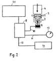
- the wire stitching device 1 shown in Figure 1 has a Stapling head 4 and a bender 3, which formed as usual can be and with those in a known manner a stapling process is feasible.
- This stapling process includes in usual Way of feeding a wire, cutting off a wire Blanks, the staple forming, the piercing of the stapling Product 2 and the bending of the two staple legs 16.
- the product 2 with the wire clamp 15th Stapled the stapling process is thus completed.
- the Stapling of the product 2 may, for example, a side stitching or a stitch at a fold of a printed product be. There are also other staples conceivable.
- the stapling head 4 here usually has a driver and a bender, which are not shown here. Also not shown is the in itself well known supply of the wire.
- the Umbieger 3 has a table 5, mounted on the two leg bender 6 are used to bend the two staple legs 16 in Direction of the arrows 18 by means of the Umbiegerstössels 7 pivotally are.
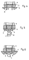
- FIGS. 4 to 6 show the bending over of the two clip legs 16 with the two leg benders 6, with a stroke of the Umbiegerstössels 7 in the direction of Arrow 19 are pivoted. With the Umbiegerstössel 7 becomes the two leg benders 6 thus the force supplied, the to bend the two staple legs 16 is required.
- a strain gauge. 9 or another suitable measuring element. With this Strain gauges 9 can upsets on Umbiegerstössel 7 are determined. Such compression of the Umbiegerstössels 7 stand in a certain relation to the force which the Umbiegerstössel 7 exerts on the two leg bender 6. Of the Strain gauge 9 may also be another force sensor, for example, a piezoelectric crystal. Basically, though Other sensors conceivable, for example, based on temperature or other state changes. During the Exercise force is the Umbiegerstössel 7 in the direction of Arrow 19 moves vertically upwards.
- the one not shown here known drive mechanism is in a frame 21st arranged. If the wire stitching device 1 has two as usual or more stitching heads 4 and 3 Umbieger, so is on each Umbiegerstössel 7 a strain gauge 9 or another measuring element appropriate.
- the strain gauge 9 is shown in FIG 2 via a signal line 10 connected to a Messauswertvorraum 8.
- the Measurement takes place over a predetermined period or distance. This is determined, for example, with a rotary encoder 12. The measurement thus takes place, for example, during a given time Strokes of the Umbiegerstössels 7.
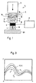
- the measurement over this Path results in a curve, which is shown by way of example in FIG is.
- the course of this curve is F within a range defined by the two curves F1 and F2 is indicated, substantially the same.
- the curve F for a correct stitch can be determined empirically and in the Messauswertvortechnisch 8 are stored. It can too several such curves F are determined and stored, For example, if different wires are used.
- the curve F shown in Figure 3 is preferably the Umbiegevorgang again. This begins after piercing the Product 2 and ends after bending over the two staple legs 16. Basically, but the curve F and the entire Stapling or another step during a staple include.
Landscapes
- Engineering & Computer Science (AREA)
- Mechanical Engineering (AREA)
- Life Sciences & Earth Sciences (AREA)
- Forests & Forestry (AREA)
- Dovetailed Work, And Nailing Machines And Stapling Machines For Wood (AREA)
- Folding Of Thin Sheet-Like Materials, Special Discharging Devices, And Others (AREA)
Description
- Fig. 1
- schematisch eine erfindungsgemässe Vorrichtung an einer Drahtheftvorrichtung,
- Fig. 2
- ein Blockschema der erfindungsgemässe Vorrichtung, und
- Fig. 3
- schematisch eine Vergleichskurve, und
- Fig. 4 bis 6
- schematisch das Umbiegen einer Drahtklammer.
Claims (8)
- Verfahren zur Kontrolle der Heftung von Produkten (2) mittels einer aus einem Klammern durchtreibenden Heftkopf (4) und einem Umbieger (7) bestehenden Drahtheftvorrichtung (1), dadurch gekennzeichnet, dass an der Drahtheftvorrichtung (1) Messmittel (9) angeordnet sind, mit denen während einer Heftung durch Krafteinwirkung an dem Heftkopf und/oder dem Umbieger eintretende Zustandsänderungen ermittelt und mit vorgegebenen Werten (F) verglichen werden.
- Verfahren nach Anspruch 1,
dadurch gekennzeichnet, dass die Messmittel (9) ein Element aufweisen, das auf Form- resp. Längenänderungen bzw. Stauchungen oder Druck anspricht. - Verfahren nach Anspruch 3, dadurch gekennzeichnet, dass das Element ein Dehnmessstreifen (9) oder ein Piezokristall ist.
- Verfahren nach Anspruch 3 oder 4, dadurch gekennzeichnet, dass das Element (9) am Umbieger (7) oder am Heftkopf angeordnet ist.
- Verfahren nach einem der Ansprüche 1 bis 5, dadurch gekennzeichnet, dass die Zustandsänderungen über einen vorbestimmten Weg oder Zeitraum ermittelt werden.
- Vorrichtung zur Durchführung des Verfahrens nach einem der Ansprüche 1 bis 5, mit einer einen Heftkopf (4) und einen Umbieger (7) aufweisenden Drahtheftvorrichtung (1) zur Heftung von Produkten (2), dadurch gekennzeichnet, dass Heftkopf und/oder Umbieger (7) mit einer Messauswertvorrichtung (8) verbunden sind, welche die ermittelten Werte der Zustandsänderungen an Heftkopf und Umbieger (7) mit den Werten einer vorgegebenen Wertekurve (F) vergleicht und im Fall einer Abweichung ein Signal an eine Anzeige und/oder eine Maschinensteuerung (14) abgibt.
- Vorrichtung nach Anspruch 6, gekennzeichnet durch einen mit der Messwertvorrichtung (8) verbundenen Drehgeber (12).
- Vorrichtung nach Anspruch 6 oder 7, dadurch gekennzeichnet, dass sie an einer Drahtheftvorrichtung (1) eines Sammelhefters angeordnet ist.
Priority Applications (2)
| Application Number | Priority Date | Filing Date | Title |
|---|---|---|---|
| DE59912985T DE59912985D1 (de) | 1999-02-15 | 1999-02-15 | Vorrichtung zur Kontrolle der Heftung |
| EP19990810135 EP1029643B1 (de) | 1999-02-15 | 1999-02-15 | Vorrichtung zur Kontrolle der Heftung |
Applications Claiming Priority (1)
| Application Number | Priority Date | Filing Date | Title |
|---|---|---|---|
| EP19990810135 EP1029643B1 (de) | 1999-02-15 | 1999-02-15 | Vorrichtung zur Kontrolle der Heftung |
Publications (2)
| Publication Number | Publication Date |
|---|---|
| EP1029643A1 EP1029643A1 (de) | 2000-08-23 |
| EP1029643B1 true EP1029643B1 (de) | 2005-12-28 |
Family
ID=8242680
Family Applications (1)
| Application Number | Title | Priority Date | Filing Date |
|---|---|---|---|
| EP19990810135 Expired - Lifetime EP1029643B1 (de) | 1999-02-15 | 1999-02-15 | Vorrichtung zur Kontrolle der Heftung |
Country Status (2)
| Country | Link |
|---|---|
| EP (1) | EP1029643B1 (de) |
| DE (1) | DE59912985D1 (de) |
Families Citing this family (2)
| Publication number | Priority date | Publication date | Assignee | Title |
|---|---|---|---|---|
| JP2005053043A (ja) * | 2003-08-01 | 2005-03-03 | Max Co Ltd | ステープル脚の折り曲げ機構 |
| EP1591272A1 (de) | 2004-04-26 | 2005-11-02 | Müller Martini Holding AG | Prüfung der Qualität einer Heftung von Druckprodukten |
Family Cites Families (4)
| Publication number | Priority date | Publication date | Assignee | Title |
|---|---|---|---|---|
| US4421264A (en) * | 1981-06-26 | 1983-12-20 | International Business Machines Corporation | Variable thickness set compensation for stapler |
| US5230457A (en) * | 1987-11-16 | 1993-07-27 | Canon Kabushiki Kaisha | Sheet stapler |
| JP2923938B2 (ja) * | 1995-02-03 | 1999-07-26 | マックス株式会社 | ホッチキスにおける綴り異常検出機構 |
| JP3125635B2 (ja) * | 1995-07-28 | 2001-01-22 | マックス株式会社 | 電動ステープラ |
-
1999
- 1999-02-15 DE DE59912985T patent/DE59912985D1/de not_active Expired - Lifetime
- 1999-02-15 EP EP19990810135 patent/EP1029643B1/de not_active Expired - Lifetime
Also Published As
| Publication number | Publication date |
|---|---|
| EP1029643A1 (de) | 2000-08-23 |
| DE59912985D1 (de) | 2006-02-02 |
Similar Documents
| Publication | Publication Date | Title |
|---|---|---|
| DE3838922C2 (de) | Heftvorrichtung | |
| DE60109886T2 (de) | Verfahren zum Nieten oder Stanzen und eine Vorrichtung zur Durchführung des Verfahrens | |
| DE202005021188U1 (de) | System aus einer Clipmaschine und einem Clipvorrat | |
| DE202016001805U1 (de) | Prüfgerät | |
| DE69604939T2 (de) | Erkennungsmechanismus für Abnormalitäten während des Heftens in einem elektrischen Heftapparat | |
| DE4338828C2 (de) | Verfahren zum Betreiben von Ziehpressen sowie hierzu geeignete Ziehpresse | |
| EP0532865B1 (de) | Vorrichtung zum Schneiden einer Textilbahn, insbesondere einer Etikettenbahn | |
| EP1029643A1 (de) | Vorrichtung zur Kontrolle der Heftung | |
| EP0651231A1 (de) | Verfahren und Vorrichtung zur Messung der Dicke von Druckereierzeugnissen, wie Zeitungen, Zeitschriften und Teilen hiervon | |
| EP2275277B1 (de) | Vorrichtung zum Anbringen eines Hinterklebestreifens mit daran befestigten Kapitalbändern am Buchblockrücken | |
| EP1591272A1 (de) | Prüfung der Qualität einer Heftung von Druckprodukten | |
| EP0825426A1 (de) | Vorrichtung zum zugspannungsgeregelten Zuführen eines elastischen Bandes od. dgl. zu einer Arbeitsmaschine, insbesondere Nähmaschine | |
| DE4103166C2 (de) | ||
| EP0641672B1 (de) | Verfahren zum Einrichten und Steuern einer Bogen verarbeitenden Maschine | |
| DE102006032829B3 (de) | Vorrichtung zum Richten oder Verformen eines Werkstückes | |
| DE102004021928A1 (de) | Prüfvorrichtung und Verfahren zur Prüfung der Funktionstüchtigkeit eines Drehimpulsgebers | |
| DE102007019009B4 (de) | Heftapparat | |
| EP1391321B1 (de) | Einrichtung zur Herstellung eines aus einem in eine Buchdecke eingehängten Buchblock gebildeten Buches | |
| DE4111404A1 (de) | Pressvorrichtung | |
| DE19515652C2 (de) | Vorrichtung zur Kontrolle der Länge und der Lage eines Kapitalbandes | |
| EP1790605B1 (de) | Verfahren zum Messen der Dicke eines Druckproduktes | |
| EP1403202B1 (de) | Verfahren zum Betrieb eines Sensors zur Erfassung von Bögen in einer bogenverarbeitenden Maschine | |
| EP1757522B1 (de) | Verfahren und Clipvorrichtung zum Verschliessen wurstförmiger Verpackungen | |
| EP1652806B1 (de) | Vorrichtung zur Erkennung von aufeinanderfolgenden Einheiten einer endlosen Bahn | |
| DD262628A1 (de) | Verfahren zur kontrolle von drahtheftungen in buchbindereimaschinen |
Legal Events
| Date | Code | Title | Description |
|---|---|---|---|
| PUAI | Public reference made under article 153(3) epc to a published international application that has entered the european phase |
Free format text: ORIGINAL CODE: 0009012 |
|
| AK | Designated contracting states |
Kind code of ref document: A1 Designated state(s): CH DE FR GB IT LI |
|
| AX | Request for extension of the european patent |
Free format text: AL;LT;LV;MK;RO;SI |
|
| 17P | Request for examination filed |
Effective date: 20001121 |
|
| AKX | Designation fees paid |
Free format text: CH DE FR GB IT LI |
|
| 17Q | First examination report despatched |
Effective date: 20041013 |
|
| GRAP | Despatch of communication of intention to grant a patent |
Free format text: ORIGINAL CODE: EPIDOSNIGR1 |
|
| GRAS | Grant fee paid |
Free format text: ORIGINAL CODE: EPIDOSNIGR3 |
|
| GRAA | (expected) grant |
Free format text: ORIGINAL CODE: 0009210 |
|
| AK | Designated contracting states |
Kind code of ref document: B1 Designated state(s): CH DE FR GB IT LI |
|
| REG | Reference to a national code |
Ref country code: GB Ref legal event code: FG4D Free format text: NOT ENGLISH |
|
| REG | Reference to a national code |
Ref country code: CH Ref legal event code: EP |
|
| REF | Corresponds to: |
Ref document number: 59912985 Country of ref document: DE Date of ref document: 20060202 Kind code of ref document: P |
|
| GBT | Gb: translation of ep patent filed (gb section 77(6)(a)/1977) |
Effective date: 20060308 |
|
| ET | Fr: translation filed | ||
| PLBE | No opposition filed within time limit |
Free format text: ORIGINAL CODE: 0009261 |
|
| STAA | Information on the status of an ep patent application or granted ep patent |
Free format text: STATUS: NO OPPOSITION FILED WITHIN TIME LIMIT |
|
| 26N | No opposition filed |
Effective date: 20060929 |
|
| REG | Reference to a national code |
Ref country code: FR Ref legal event code: PLFP Year of fee payment: 18 |
|
| PGFP | Annual fee paid to national office [announced via postgrant information from national office to epo] |
Ref country code: IT Payment date: 20160226 Year of fee payment: 18 |
|
| PGFP | Annual fee paid to national office [announced via postgrant information from national office to epo] |
Ref country code: FR Payment date: 20160224 Year of fee payment: 18 Ref country code: GB Payment date: 20160223 Year of fee payment: 18 |
|
| PGFP | Annual fee paid to national office [announced via postgrant information from national office to epo] |
Ref country code: DE Payment date: 20170216 Year of fee payment: 19 |
|
| PGFP | Annual fee paid to national office [announced via postgrant information from national office to epo] |
Ref country code: CH Payment date: 20170522 Year of fee payment: 19 |
|
| GBPC | Gb: european patent ceased through non-payment of renewal fee |
Effective date: 20170215 |
|
| REG | Reference to a national code |
Ref country code: FR Ref legal event code: ST Effective date: 20171031 |
|
| PG25 | Lapsed in a contracting state [announced via postgrant information from national office to epo] |
Ref country code: FR Free format text: LAPSE BECAUSE OF NON-PAYMENT OF DUE FEES Effective date: 20170228 |
|
| PG25 | Lapsed in a contracting state [announced via postgrant information from national office to epo] |
Ref country code: IT Free format text: LAPSE BECAUSE OF NON-PAYMENT OF DUE FEES Effective date: 20170215 Ref country code: GB Free format text: LAPSE BECAUSE OF NON-PAYMENT OF DUE FEES Effective date: 20170215 |
|
| REG | Reference to a national code |
Ref country code: DE Ref legal event code: R119 Ref document number: 59912985 Country of ref document: DE |
|
| REG | Reference to a national code |
Ref country code: CH Ref legal event code: PL |
|
| PG25 | Lapsed in a contracting state [announced via postgrant information from national office to epo] |
Ref country code: LI Free format text: LAPSE BECAUSE OF NON-PAYMENT OF DUE FEES Effective date: 20180228 Ref country code: CH Free format text: LAPSE BECAUSE OF NON-PAYMENT OF DUE FEES Effective date: 20180228 |
|
| PG25 | Lapsed in a contracting state [announced via postgrant information from national office to epo] |
Ref country code: DE Free format text: LAPSE BECAUSE OF NON-PAYMENT OF DUE FEES Effective date: 20180901 |