EP1029588A1 - Füllkörper mit Kreuzkanalstruktur - Google Patents
Füllkörper mit Kreuzkanalstruktur Download PDFInfo
- Publication number
- EP1029588A1 EP1029588A1 EP00810029A EP00810029A EP1029588A1 EP 1029588 A1 EP1029588 A1 EP 1029588A1 EP 00810029 A EP00810029 A EP 00810029A EP 00810029 A EP00810029 A EP 00810029A EP 1029588 A1 EP1029588 A1 EP 1029588A1
- Authority
- EP
- European Patent Office
- Prior art keywords
- channels
- layers
- packing
- wall pieces
- lateral
- Prior art date
- Legal status (The legal status is an assumption and is not a legal conclusion. Google has not performed a legal analysis and makes no representation as to the accuracy of the status listed.)
- Granted
Links
Images


Classifications
-
- B—PERFORMING OPERATIONS; TRANSPORTING
- B01—PHYSICAL OR CHEMICAL PROCESSES OR APPARATUS IN GENERAL
- B01J—CHEMICAL OR PHYSICAL PROCESSES, e.g. CATALYSIS OR COLLOID CHEMISTRY; THEIR RELEVANT APPARATUS
- B01J19/00—Chemical, physical or physico-chemical processes in general; Their relevant apparatus
- B01J19/32—Packing elements in the form of grids or built-up elements for forming a unit or module inside the apparatus for mass or heat transfer
-
- B—PERFORMING OPERATIONS; TRANSPORTING
- B01—PHYSICAL OR CHEMICAL PROCESSES OR APPARATUS IN GENERAL
- B01J—CHEMICAL OR PHYSICAL PROCESSES, e.g. CATALYSIS OR COLLOID CHEMISTRY; THEIR RELEVANT APPARATUS
- B01J2219/00—Chemical, physical or physico-chemical processes in general; Their relevant apparatus
- B01J2219/32—Details relating to packing elements in the form of grids or built-up elements for forming a unit of module inside the apparatus for mass or heat transfer
- B01J2219/322—Basic shape of the elements
- B01J2219/32203—Sheets
- B01J2219/3221—Corrugated sheets
-
- B—PERFORMING OPERATIONS; TRANSPORTING
- B01—PHYSICAL OR CHEMICAL PROCESSES OR APPARATUS IN GENERAL
- B01J—CHEMICAL OR PHYSICAL PROCESSES, e.g. CATALYSIS OR COLLOID CHEMISTRY; THEIR RELEVANT APPARATUS
- B01J2219/00—Chemical, physical or physico-chemical processes in general; Their relevant apparatus
- B01J2219/32—Details relating to packing elements in the form of grids or built-up elements for forming a unit of module inside the apparatus for mass or heat transfer
- B01J2219/322—Basic shape of the elements
- B01J2219/32203—Sheets
- B01J2219/32213—Plurality of essentially parallel sheets
-
- B—PERFORMING OPERATIONS; TRANSPORTING
- B01—PHYSICAL OR CHEMICAL PROCESSES OR APPARATUS IN GENERAL
- B01J—CHEMICAL OR PHYSICAL PROCESSES, e.g. CATALYSIS OR COLLOID CHEMISTRY; THEIR RELEVANT APPARATUS
- B01J2219/00—Chemical, physical or physico-chemical processes in general; Their relevant apparatus
- B01J2219/32—Details relating to packing elements in the form of grids or built-up elements for forming a unit of module inside the apparatus for mass or heat transfer
- B01J2219/322—Basic shape of the elements
- B01J2219/32203—Sheets
- B01J2219/32224—Sheets characterised by the orientation of the sheet
- B01J2219/32227—Vertical orientation
-
- B—PERFORMING OPERATIONS; TRANSPORTING
- B01—PHYSICAL OR CHEMICAL PROCESSES OR APPARATUS IN GENERAL
- B01J—CHEMICAL OR PHYSICAL PROCESSES, e.g. CATALYSIS OR COLLOID CHEMISTRY; THEIR RELEVANT APPARATUS
- B01J2219/00—Chemical, physical or physico-chemical processes in general; Their relevant apparatus
- B01J2219/32—Details relating to packing elements in the form of grids or built-up elements for forming a unit of module inside the apparatus for mass or heat transfer
- B01J2219/322—Basic shape of the elements
- B01J2219/32203—Sheets
- B01J2219/32237—Sheets comprising apertures or perforations
-
- B—PERFORMING OPERATIONS; TRANSPORTING
- B01—PHYSICAL OR CHEMICAL PROCESSES OR APPARATUS IN GENERAL
- B01J—CHEMICAL OR PHYSICAL PROCESSES, e.g. CATALYSIS OR COLLOID CHEMISTRY; THEIR RELEVANT APPARATUS
- B01J2219/00—Chemical, physical or physico-chemical processes in general; Their relevant apparatus
- B01J2219/32—Details relating to packing elements in the form of grids or built-up elements for forming a unit of module inside the apparatus for mass or heat transfer
- B01J2219/322—Basic shape of the elements
- B01J2219/32203—Sheets
- B01J2219/32248—Sheets comprising areas that are raised or sunken from the plane of the sheet
-
- B—PERFORMING OPERATIONS; TRANSPORTING
- B01—PHYSICAL OR CHEMICAL PROCESSES OR APPARATUS IN GENERAL
- B01J—CHEMICAL OR PHYSICAL PROCESSES, e.g. CATALYSIS OR COLLOID CHEMISTRY; THEIR RELEVANT APPARATUS
- B01J2219/00—Chemical, physical or physico-chemical processes in general; Their relevant apparatus
- B01J2219/32—Details relating to packing elements in the form of grids or built-up elements for forming a unit of module inside the apparatus for mass or heat transfer
- B01J2219/322—Basic shape of the elements
- B01J2219/32203—Sheets
- B01J2219/32255—Other details of the sheets
-
- B—PERFORMING OPERATIONS; TRANSPORTING
- B01—PHYSICAL OR CHEMICAL PROCESSES OR APPARATUS IN GENERAL
- B01J—CHEMICAL OR PHYSICAL PROCESSES, e.g. CATALYSIS OR COLLOID CHEMISTRY; THEIR RELEVANT APPARATUS
- B01J2219/00—Chemical, physical or physico-chemical processes in general; Their relevant apparatus
- B01J2219/32—Details relating to packing elements in the form of grids or built-up elements for forming a unit of module inside the apparatus for mass or heat transfer
- B01J2219/322—Basic shape of the elements
- B01J2219/32203—Sheets
- B01J2219/32265—Sheets characterised by the orientation of blocks of sheets
- B01J2219/32272—Sheets characterised by the orientation of blocks of sheets relating to blocks in superimposed layers
-
- B—PERFORMING OPERATIONS; TRANSPORTING
- B01—PHYSICAL OR CHEMICAL PROCESSES OR APPARATUS IN GENERAL
- B01J—CHEMICAL OR PHYSICAL PROCESSES, e.g. CATALYSIS OR COLLOID CHEMISTRY; THEIR RELEVANT APPARATUS
- B01J2219/00—Chemical, physical or physico-chemical processes in general; Their relevant apparatus
- B01J2219/32—Details relating to packing elements in the form of grids or built-up elements for forming a unit of module inside the apparatus for mass or heat transfer
- B01J2219/322—Basic shape of the elements
- B01J2219/32286—Grids or lattices
-
- B—PERFORMING OPERATIONS; TRANSPORTING
- B01—PHYSICAL OR CHEMICAL PROCESSES OR APPARATUS IN GENERAL
- B01J—CHEMICAL OR PHYSICAL PROCESSES, e.g. CATALYSIS OR COLLOID CHEMISTRY; THEIR RELEVANT APPARATUS
- B01J2219/00—Chemical, physical or physico-chemical processes in general; Their relevant apparatus
- B01J2219/32—Details relating to packing elements in the form of grids or built-up elements for forming a unit of module inside the apparatus for mass or heat transfer
- B01J2219/324—Composition or microstructure of the elements
- B01J2219/32408—Metal
-
- B—PERFORMING OPERATIONS; TRANSPORTING
- B01—PHYSICAL OR CHEMICAL PROCESSES OR APPARATUS IN GENERAL
- B01J—CHEMICAL OR PHYSICAL PROCESSES, e.g. CATALYSIS OR COLLOID CHEMISTRY; THEIR RELEVANT APPARATUS
- B01J2219/00—Chemical, physical or physico-chemical processes in general; Their relevant apparatus
- B01J2219/32—Details relating to packing elements in the form of grids or built-up elements for forming a unit of module inside the apparatus for mass or heat transfer
- B01J2219/324—Composition or microstructure of the elements
- B01J2219/32425—Ceramic
Definitions
- the invention relates to a filler body with a cross-channel structure according to Preamble of claim 1, a column with such a packing as Pack and a mixing device with such a packing as static mixer structure.
- the object of the invention is to provide a packing with a cross-channel structure create for which the desired homogenization and mixing effects adjust with a reduced energy dissipation. Compared to the Ratios in known fillers with a cross-channel structure are said to flow body to be created the flow resistance be smaller, but the separation performance of a mass transfer column or the mixing effect of a static mixer should remain largely the same. This task will solved by the packing defined in claim 1.
- the packing with a cross-channel structure is for a packing column or a static mixing device provided. It is made up of contiguous Layers built up in which channels are arranged parallel to each other are. Lateral areas extend at interfaces between adjacent layers Channels that are open to each other. These lateral channels form one crosswise arrangement. At least some of the layers also contain central channels for the lateral channels. A material separation the boundaries between the central and lateral channels is around one Half made with regularly arranged wall pieces; in the zones the other half, the channel borders are open.
- the layers of the packing according to the invention include lateral ones Channels additionally central channels that are only partially through walls from the lateral channels are delimited.
- the lateral channels correspond to the Channels of the known cross-channel structure, in which the parallel channels the same layer are separated by walls over their entire length.
- This primary Vertebrae induce secondary vertebrae in the central channels. Thanks to the central channels, it is largely the same size Energy dissipation achieves a mixing effect in a larger volume.
- the dependent claims 2 to 7 relate to advantageous Embodiments of the packing according to the invention.
- Objects of Claims 8 to 10 are a column and a mixing device with such Packing.
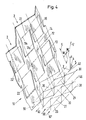
- a layer 10 of a packing 1 according to the invention - see FIGS. 1, 4 and 11 - is made of a grid-like slit and formed sheet educated. Instead of a sheet, a film or wire mesh can also be used be provided.
- Slots 11 have slot edges 11 a and 11b, one Open area 22 or 22 '(Fig. 4).
- the slots 11 have End points A, B and A ', B', which are a grid with triangles ABA 'and Form BA'B '.
- Metals, ceramic materials and / or plastics can be selected.
- the filler body 1 is composed of a multiplicity of adjacent layers 10 constructed in which channels 2 are arranged parallel to each other.
- the Channels 2 are inclined with respect to a main flow direction. This Direction is parallel to the z-axis in Fig.4.
- channels 2 namely lateral, extend between adjacent layers 10 Channels in FIG. 4 on the basis of cross sections lying in an x-y plane are identifiable.
- the lateral channels, each with a triangular cross section are designated there by reference number 20.
- These lateral channels 20 are open to each other; they form a crosswise arrangement.
- the location 10 contains 20 central channels 21 in addition to the lateral channels each square cross-section.
- a physical separation at the borders between the central and lateral channels 2. is about half of them regularly arranged pieces of wall made; in the zones of the other half, the channel boundaries are open.
- the interfaces of the channels 2 are formed by comb-shaped wall pieces given. Folded edges or combs 12 and 14 of these wall pieces are alternately on both sides of a central plane 4 of the layer 10, namely the x-z plane in Fig. 4, arranged; they are parallel to this Level.
- the combs 12 and 14 are in front or behind with respect to the plane of the drawing, which is parallel to the ridges 12, 14 extends. Further folding edges 13 and 15 lie in the central plane 4.
- the Direction 5 of the channels 2 includes an angle W with the z-axis (FIG. 4) on the left side of the z-axis when looking in the y-direction.
- the channel direction 5 'of adjacent layers 10 the z-axis also the angle W, but on the right side.
- This Tilt angle W is greater than 10 ° and less than 70 °.
- the projection of the Channel directions 5 and 5 'in the x-y plane are shown in FIG. 4 as arrows 50 and 50' specified.
- Figures 2 and 3 show two parallel cross sections through the layer 10, the correspond to lines II-II and III-III in Fig. 1.
- dash-dotted straight lines 30 and 40 are the positions of the interfaces 3 and the central plane 4 specified.
- Fig. 2 are only the folded edges lying at the interfaces 3 12 and 14 can be seen, in Fig. 2 also the folded edges 13 and 15 in the Central plane 4.
- the cross section of FIG. 3 cuts the slots 11 (edges 11a, 11b) at positions a, b, c and d.
- the regularly arranged wall pieces of the channels 2 have free ones Edges, namely the slot edges 11a and 11b.
- These edges 11a and 11 b can be curved or toothed (not shown). They are an advantage however, straight and at least approximate to fall lines, i.e. H. on Lines that lie on a vertical plane (parallel to the z-axis) and the with respect to the surface of the layer 10 are aligned so that they stand perpendicular to a horizontal on this surface.
- This advantageous embodiment is shown in Fig. 6.
- the direction of the fall line is indicated there by an arrow 19.
- the geometry of a layer 10 can be characterized by the angle of inclination W, the angles of the folded edges 12, 14 and the arrangement of the slots 11.
- the arrangement of the slots 11 can be determined by the distance between the corner points A and B, the distances ⁇ A and ⁇ B and, for example, two triangular angles ⁇ and ⁇ (FIG. 7).
- Fig. 10 to an environment of the open area 22 in Fig. 6, the with a cross 220 is marked, further details are shown which show the position 10 can have: the material limits of the channels 2, the channel walls, are grooved, d. H. structured with fine channels.
- the grooving 17 is transverse to the Fall lines (edges 11a, 11b).
- the channel walls can also be added be perforated, for example with round holes 18.
- the packing according to the invention does not have to consist of layers of the of the same type. Individual layers can also be made unslit sheets (or foils or fabrics) are made, the each have a wave shape, in particular are folded in a zigzag fashion. At Such a structure, it is advantageous if the layers of the different Types are arranged in a regular order, so for example in an alternating arrangement of a) layers with sheets of the type shown in Figures 1 to 10 and b) layers wavy, unslit sheets.
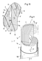
- the filler 1 is generally composed of a plurality of stacked packing elements constructed, each Element forms an area of the pack with the layers aligned in the same direction and the horizontal directions of the layers of adjacent elements are different cross.
- 11 shows the structural structure of such a packing 1 shown, namely with interfaces 3 of two packing elements 1 a and 1b, which is in the cylindrical wall 100 of a column or a static Mixer are arranged.
- the dash-dotted lines 30 give the upper Edges of interfaces 3, not shown.
- the arrows 6 and 7 indicate main flow directions of fluids which are for the purpose of one Mixing and / or a material exchange passed through the packing 1 become.
- Wall pieces of the layers 10 can be formed by additional slots and Formings can be structured further, so that, for example, smaller ones there are comb-shaped folded wall pieces that are similar to the wall pieces of the channels 2 (cf. FIG. 4) but are somewhat smaller than these.
- a cross-channel structure with such a fine structure is known from the US-A 4 710 326 known.
- the channels 2 are in all exemplary embodiments as straight-line channels shown. But they can also show changes of direction, especially in marginal zones at the upper and / or lower ends of the Packing elements 1a and 1b in Fig. 11.
- the pack are each a lower zone, a middle zone and an upper zone distinguishable.
- the zones on the Edges of the packing elements can be due to a suitable Shaping the flow resistance compared to that of the middle zone be reduced.
- the surfaces of the packing according to the invention can have a Have coating with catalytically active substances.
- Such packing can be carried out in columns for carrying out reactive distillation use or as a catalyst carrier in exhaust gas catalysts.
Abstract
Description
- Fig. 1
- eine Draufsicht auf eine Lage des erfindungsgemässen Füllkörpers,
- Fig. 2, 3
- zwei Querschnitte durch die Lage der Fig. 1,
- Fig. 4
- eine Schrägbilddarstellung derselben Lage,
- Fig. 5
- eine schematische Darstellung zu den Strömungsverhältnissen im erfindungsgemässen Füllkörper,
- Fig. 6
- eine besonders vorteilhafte Geometrie der Füllkörperlage,
- Fig. 7, 8
- eine weitere Ausführungsform in einer den Figuren 1 und 2 entsprechenden Darstellung,
- Fig. 9
- einen Variante zur Lage der Fig. 8,
- Fig. 10
- eine Detaildarstellung zu einer Lage des in Fig. 6 gezeigten Typs und
- Fig. 11
- eine schematische Darstellung zu einer Kolonne oder einem statischen Mischer mit einem erfindungsgemässen Füllkörper.
Claims (10)
- Füllkörper (1) mit Kreuzkanalstruktur, für eine Packungskolonne oder eine statische Mischeinrichtung, welcher Füllkörper aus aneinander grenzenden Lagen (10) aufgebaut ist, in denen jeweils Kanäle (2) parallel zueinander angeordnet sind, wobei an Grenzflächen (3) zwischen benachbarten Lagen sich laterale Kanäle (20) erstrecken, die gegeneinander offen sind, und diese lateralen Kanäle eine kreuzweise Anordnung bilden,
dadurch gekennzeichnet, dass zumindest ein Teil der Lagen (10) zusätzlich zu den lateralen Kanälen (20) jeweils zentrale Kanäle (21) enthalten, wobei eine materielle Trennung an den Grenzen zwischen den zentralen und lateralen Kanälen zu rund einer Hälfte mit regelmässig angeordneten Wandstücken hergestellt ist und die Kanalgrenzen in den Zonen der anderen Hälfte offen sind. - Füllkörper nach Anspruch 1, dadurch gekennzeichnet, dass die Lagen (10) jeweils aus einem rasterartig geschlitzten sowie umgeformten Blech gebildet sind, wobei die Kanalgrenzen durch kammförmig gefaltete Wandstücke gegeben sind und die Kämme (12, 14) dieser Wandstücke reihenweise alternierend auf beiden Seiten einer Zentralebene (4) der Lage und parallel zu dieser Ebene angeordnet sind, wobei anstelle des Blechs auch eine Folie oder ein Drahtgewebe vorgesehen sein kann und für das Material des Blechs bzw. der Folie oder des Gewebes Metalle, keramische Stoffe und/oder Kunststoffe gewählt werden können.
- Füllkörper nach Anspruch 2, dadurch gekennzeichnet, dass einzelne Wandstücke durch zusätzliche Schlitzbildungen und Umformungen weiter strukturiert sind, insbesondere eine Feinstrukturierung aufweisen.
- Füllkörper nach einem der Ansprüche 1 bis 3, dadurch gekennzeichnet, dass alle Kanäle zu einer Hauptströmungsrichtung (6, 7) geneigt sind und dass die Neigungswinkel (W) bezüglich der Hauptströmungsrichtung grösser als 10° und kleiner als 70° sind, wobei insbesondere die sich kreuzenden Kanäle (2) benachbarter Lagen (10), die bezüglich der Hauptströmungsrichtung entgegengesetzt geneigt sind, Neigungswinkel haben, die betragsmässig weitgehend gleich gross sind.
- Füllkörper nach einem der Ansprüche 1 bis 4, dadurch gekennzeichnet, dass die regelmässig angeordneten Wandstücke freie Kanten (11a, 11 b) aufweisen, die geradlinig sind und die zumindest angenähert auf Falllinien liegen, d. h. auf Linien, die auf einer vertikalen Ebene liegen und deren Richtung senkrecht zu einer Horizontalen auf der Oberfläche ist.
- Füllkörper nach einem der Ansprüche 1 bis 5, dadurch gekennzeichnet, dass die Kanalwände rilliert sind oder eine andere Strukturierung aufweisen und/oder dass die Kanalwände zusätzlich perforiert sind, beispielsweise mit runden Löchern (18).
- Füllkörper nach einem der Ansprüche 1 bis 6, dadurch gekennzeichnet, dass einzelne, regelmässig angeordnete Lagen aus ungeschlitzten Blechen bzw. Folien oder Geweben hergestellt sind, die jeweils eine Wellenform haben, insbesondere zickzackartig gefaltet sind.
- Kolonne mit einem Füllkörper (1) gemäss einem der Ansprüche 1 bis 7 als Packung für einen Stoff- und/oder Wärmetausch zwischen einerseits einem Rieselfilm auf Oberflächen der Packung und andererseits einem Gasstrom, der eine Vielzahl von durch die Packungsoberflächen gebildeten Kanälen (2) durchströmt, wobei die Oberflächen der Packung eine Beschichtung mit katalytisch wirksamen Stoffen aufweisen können.
- Kolonne nach Anspruch 8, dadurch gekennzeichnet, dass der Füllkörper (1) aus mehreren, übereinander angeordneten Packungselementen (1a, 1b) aufgebaut ist, jedes Element einen Bereich der Packung mit gleich ausgerichteten Lagen (10) bildet und die horizontalen Richtungen der Lagen benachbarter Elemente sich kreuzen.
- Mischeinrichtung mit einem Rohr (100) und einer im Rohr angeordneten statischen Mischerstruktur (1) in Form eines Füllkörpers gemäss einem der Ansprüche 1 bis 7, für eine Durchmischung von fliessfähigen Stoffen, die das Rohr in gleicher Richtung (6 oder 7) durchströmen, wobei die Oberflächen der Mischerstruktur eine Beschichtung mit katalytisch wirksamen Stoffen aufweisen können.
Priority Applications (1)
| Application Number | Priority Date | Filing Date | Title |
|---|---|---|---|
| EP00810029A EP1029588B2 (de) | 1999-02-12 | 2000-01-13 | Füllkörper mit Kreuzkanalstruktur |
Applications Claiming Priority (3)
| Application Number | Priority Date | Filing Date | Title |
|---|---|---|---|
| EP99810130 | 1999-02-12 | ||
| EP99810130 | 1999-02-12 | ||
| EP00810029A EP1029588B2 (de) | 1999-02-12 | 2000-01-13 | Füllkörper mit Kreuzkanalstruktur |
Publications (3)
| Publication Number | Publication Date |
|---|---|
| EP1029588A1 true EP1029588A1 (de) | 2000-08-23 |
| EP1029588B1 EP1029588B1 (de) | 2004-06-02 |
| EP1029588B2 EP1029588B2 (de) | 2007-09-05 |
Family
ID=26073751
Family Applications (1)
| Application Number | Title | Priority Date | Filing Date |
|---|---|---|---|
| EP00810029A Expired - Lifetime EP1029588B2 (de) | 1999-02-12 | 2000-01-13 | Füllkörper mit Kreuzkanalstruktur |
Country Status (1)
| Country | Link |
|---|---|
| EP (1) | EP1029588B2 (de) |
Cited By (7)
| Publication number | Priority date | Publication date | Assignee | Title |
|---|---|---|---|---|
| FR2826879A1 (fr) * | 2001-07-06 | 2003-01-10 | Air Liquide | Bande pour module de garnissage, module et installation correspondants |
| WO2003004148A2 (fr) | 2001-07-06 | 2003-01-16 | L'air Liquide Societe Anonyme A Directoire Et Conseil De Surveillance Pour L'etude Et L'exploitation Des Procedes Georges Claude | Bande pour module de garnissage, module et installation correspondants |
| DE202008007801U1 (de) | 2007-09-19 | 2008-08-21 | Kettenbach Gmbh & Co. Kg | Behälter |
| FR2913353A1 (fr) * | 2007-03-09 | 2008-09-12 | Inst Francais Du Petrole | Garnissage structure haute performance pour colonne de mise en contact de fluides et methode de fabrication. |
| CN1965205B (zh) * | 2004-06-04 | 2013-01-23 | 乔治洛德方法研究和开发液化空气有限公司 | 蒸馏塔 |
| EP2656908A1 (de) | 2012-04-25 | 2013-10-30 | Umicore AG & Co. KG | Statischer Gasmischer |
| US10376860B2 (en) | 2013-06-07 | 2019-08-13 | Sulzer Chemtech Ag | Packing layer for structured packing |
Citations (4)
| Publication number | Priority date | Publication date | Assignee | Title |
|---|---|---|---|---|
| DE1501375A1 (de) * | 1966-06-10 | 1970-01-22 | Escher Wyss Gmbh | Fuellkoerperplatten fuer Waerme- und Stoffaustausch-Vorrichtungen |
| DE2942481A1 (de) * | 1979-10-20 | 1981-04-30 | Bayer Ag, 5090 Leverkusen | Rieselfuellung fuer stoffaustauschkolonnen |
| EP0129272A1 (de) * | 1983-05-27 | 1984-12-27 | FDO Technische Adviseurs B.V. | Vorrichtung zur Ausführung eines Stoffauswechselverfahrens |
| US5578254A (en) * | 1993-11-09 | 1996-11-26 | Mix; Thomas W. | Structured packing elements |
Family Cites Families (2)
| Publication number | Priority date | Publication date | Assignee | Title |
|---|---|---|---|---|
| CA1243941A (en) † | 1985-09-05 | 1988-11-01 | Min A. Hsia | Packing element for exchange column |
| US4710326A (en) † | 1986-08-29 | 1987-12-01 | Seah Alexander M | Corrugated packing and methods of use |
-
2000
- 2000-01-13 EP EP00810029A patent/EP1029588B2/de not_active Expired - Lifetime
Patent Citations (4)
| Publication number | Priority date | Publication date | Assignee | Title |
|---|---|---|---|---|
| DE1501375A1 (de) * | 1966-06-10 | 1970-01-22 | Escher Wyss Gmbh | Fuellkoerperplatten fuer Waerme- und Stoffaustausch-Vorrichtungen |
| DE2942481A1 (de) * | 1979-10-20 | 1981-04-30 | Bayer Ag, 5090 Leverkusen | Rieselfuellung fuer stoffaustauschkolonnen |
| EP0129272A1 (de) * | 1983-05-27 | 1984-12-27 | FDO Technische Adviseurs B.V. | Vorrichtung zur Ausführung eines Stoffauswechselverfahrens |
| US5578254A (en) * | 1993-11-09 | 1996-11-26 | Mix; Thomas W. | Structured packing elements |
Cited By (12)
| Publication number | Priority date | Publication date | Assignee | Title |
|---|---|---|---|---|
| FR2826879A1 (fr) * | 2001-07-06 | 2003-01-10 | Air Liquide | Bande pour module de garnissage, module et installation correspondants |
| WO2003004148A2 (fr) | 2001-07-06 | 2003-01-16 | L'air Liquide Societe Anonyme A Directoire Et Conseil De Surveillance Pour L'etude Et L'exploitation Des Procedes Georges Claude | Bande pour module de garnissage, module et installation correspondants |
| WO2003004148A3 (fr) * | 2001-07-06 | 2003-04-10 | Air Liquide | Bande pour module de garnissage, module et installation correspondants |
| CN1965205B (zh) * | 2004-06-04 | 2013-01-23 | 乔治洛德方法研究和开发液化空气有限公司 | 蒸馏塔 |
| FR2913353A1 (fr) * | 2007-03-09 | 2008-09-12 | Inst Francais Du Petrole | Garnissage structure haute performance pour colonne de mise en contact de fluides et methode de fabrication. |
| WO2008132311A3 (fr) * | 2007-03-09 | 2008-12-24 | Inst Francais Du Petrole | Garnissage structure haute performance pour colonne de mise en contact de fluides et méthode de fabrication |
| US8646758B2 (en) | 2007-03-09 | 2014-02-11 | Ifp | High performance structured packing for fluid exchange column and fabrication method |
| DE202008007801U1 (de) | 2007-09-19 | 2008-08-21 | Kettenbach Gmbh & Co. Kg | Behälter |
| EP2656908A1 (de) | 2012-04-25 | 2013-10-30 | Umicore AG & Co. KG | Statischer Gasmischer |
| DE102012008108A1 (de) | 2012-04-25 | 2013-10-31 | Umicore Ag & Co. Kg | Statischer Gasmischer |
| US9346026B2 (en) | 2012-04-25 | 2016-05-24 | Umicore Ag & Co. Kg | Static gas mixer |
| US10376860B2 (en) | 2013-06-07 | 2019-08-13 | Sulzer Chemtech Ag | Packing layer for structured packing |
Also Published As
| Publication number | Publication date |
|---|---|
| EP1029588B1 (de) | 2004-06-02 |
| EP1029588B2 (de) | 2007-09-05 |
Similar Documents
| Publication | Publication Date | Title |
|---|---|---|
| DE2219130C2 (de) | Kontaktkoerper fuer den waerme- und/oder stoffaustausch | |
| EP0221095B1 (de) | Wirbelpackung und verfahren zu deren herstellung | |
| DE2060178C3 (de) | Grid-Austauschpackung für Kolonnen | |
| EP0418338B1 (de) | Mehrzügige wirbelpackung | |
| EP2496342B1 (de) | Gewelltes packungsgitter sowie geordnete, aus mehreren packungsgittern aufgebaute packung | |
| EP0069241A1 (de) | Packung für Stoffaustauschkolonnen und Verfahren zur Herstellung der Packung | |
| DE2601890A1 (de) | Packungskoerper fuer stoffaustauschkolonnen | |
| DE8330573U1 (de) | Fuellkoerper fuer stoffaustauschkolonnen | |
| EP0640385A1 (de) | Packung mit katalytischen oder adsorbierenden Mitteln | |
| EP0151693A2 (de) | Stoffaustauschkolonne | |
| DE3116557A1 (de) | Vorrichtung zur invertierung und mischung von stroemenden stoffen | |
| EP0764462A2 (de) | Füllkörper, insbesondere für Stoff- und/oder Wärmeaustauschkolonnen oder/ -türme | |
| EP0776695B1 (de) | Packung für eine Gegenstrom-Hochdruckkolonne | |
| EP1477224B1 (de) | Verwendung einer Kreuzkanalpackung aus Metallgewebe | |
| EP0638358B1 (de) | Wirbelpackung für Stoffaustauschkolonnen und statische Mischer | |
| WO2014195233A1 (de) | Packungslage für eine strukturierte packung | |
| DE2516078C3 (de) | Systematisch aufgebaute Packung für Stoffaustauschkolonnen | |
| EP1029588B1 (de) | Füllkörper mit Kreuzkanalstruktur | |
| WO2006056419A1 (de) | Geordnete packung für wärme und/oder stoffaustausch | |
| DE69820880T2 (de) | Wärmetauscherwirbelerzeuger mit unterbrochenen wellungen | |
| EP3535539B1 (de) | Einbaueinrichtung für eine vorrichtung zur behandlung eines nutzfluids mit einem arbeitsfluid | |
| EP1586375B1 (de) | Füllkorper | |
| WO2004079748A2 (de) | Abstandhalter | |
| DE202008016603U1 (de) | Wellrippe für Wärmeaustauscher | |
| DE1948282B2 (de) | Wabenkorper zum Behandeln von Flüssigkeiten mittels Gasen |
Legal Events
| Date | Code | Title | Description |
|---|---|---|---|
| PUAI | Public reference made under article 153(3) epc to a published international application that has entered the european phase |
Free format text: ORIGINAL CODE: 0009012 |
|
| AK | Designated contracting states |
Kind code of ref document: A1 Designated state(s): AT BE CH CY DE DK ES FI FR GB GR IE IT LI LU MC NL PT SE |
|
| AX | Request for extension of the european patent |
Free format text: AL;LT;LV;MK;RO;SI |
|
| 17P | Request for examination filed |
Effective date: 20010125 |
|
| AKX | Designation fees paid |
Free format text: AT BE CH CY DE DK ES FI FR GB GR IE IT LI LU MC NL PT SE |
|
| GRAP | Despatch of communication of intention to grant a patent |
Free format text: ORIGINAL CODE: EPIDOSNIGR1 |
|
| GRAS | Grant fee paid |
Free format text: ORIGINAL CODE: EPIDOSNIGR3 |
|
| GRAA | (expected) grant |
Free format text: ORIGINAL CODE: 0009210 |
|
| AK | Designated contracting states |
Kind code of ref document: B1 Designated state(s): AT BE CH CY DE DK ES FI FR GB GR IE IT LI LU MC NL PT SE |
|
| PG25 | Lapsed in a contracting state [announced via postgrant information from national office to epo] |
Ref country code: FI Free format text: LAPSE BECAUSE OF FAILURE TO SUBMIT A TRANSLATION OF THE DESCRIPTION OR TO PAY THE FEE WITHIN THE PRESCRIBED TIME-LIMIT Effective date: 20040602 Ref country code: IE Free format text: LAPSE BECAUSE OF FAILURE TO SUBMIT A TRANSLATION OF THE DESCRIPTION OR TO PAY THE FEE WITHIN THE PRESCRIBED TIME-LIMIT Effective date: 20040602 |
|
| REG | Reference to a national code |
Ref country code: GB Ref legal event code: FG4D Free format text: NOT ENGLISH |
|
| REG | Reference to a national code |
Ref country code: CH Ref legal event code: NV Representative=s name: SULZER MANAGEMENT AG PATENTABTEILUNG/0067 Ref country code: CH Ref legal event code: EP |
|
| GBT | Gb: translation of ep patent filed (gb section 77(6)(a)/1977) |
Effective date: 20040602 |
|
| REF | Corresponds to: |
Ref document number: 50006636 Country of ref document: DE Date of ref document: 20040708 Kind code of ref document: P |
|
| REG | Reference to a national code |
Ref country code: IE Ref legal event code: FG4D Free format text: GERMAN |
|
| PG25 | Lapsed in a contracting state [announced via postgrant information from national office to epo] |
Ref country code: SE Free format text: LAPSE BECAUSE OF FAILURE TO SUBMIT A TRANSLATION OF THE DESCRIPTION OR TO PAY THE FEE WITHIN THE PRESCRIBED TIME-LIMIT Effective date: 20040902 Ref country code: GR Free format text: LAPSE BECAUSE OF FAILURE TO SUBMIT A TRANSLATION OF THE DESCRIPTION OR TO PAY THE FEE WITHIN THE PRESCRIBED TIME-LIMIT Effective date: 20040902 Ref country code: DK Free format text: LAPSE BECAUSE OF FAILURE TO SUBMIT A TRANSLATION OF THE DESCRIPTION OR TO PAY THE FEE WITHIN THE PRESCRIBED TIME-LIMIT Effective date: 20040902 |
|
| REG | Reference to a national code |
Ref country code: IE Ref legal event code: FD4D |
|
| PG25 | Lapsed in a contracting state [announced via postgrant information from national office to epo] |
Ref country code: CY Free format text: LAPSE BECAUSE OF FAILURE TO SUBMIT A TRANSLATION OF THE DESCRIPTION OR TO PAY THE FEE WITHIN THE PRESCRIBED TIME-LIMIT Effective date: 20050113 Ref country code: LU Free format text: LAPSE BECAUSE OF NON-PAYMENT OF DUE FEES Effective date: 20050113 |
|
| PG25 | Lapsed in a contracting state [announced via postgrant information from national office to epo] |
Ref country code: MC Free format text: LAPSE BECAUSE OF NON-PAYMENT OF DUE FEES Effective date: 20050131 Ref country code: AT Free format text: LAPSE BECAUSE OF NON-PAYMENT OF DUE FEES Effective date: 20050131 |
|
| REG | Reference to a national code |
Ref country code: ES Ref legal event code: FG2A Ref document number: 2222171 Country of ref document: ES Kind code of ref document: T3 |
|
| ET | Fr: translation filed | ||
| PLAQ | Examination of admissibility of opposition: information related to despatch of communication + time limit deleted |
Free format text: ORIGINAL CODE: EPIDOSDOPE2 |
|
| PLAR | Examination of admissibility of opposition: information related to receipt of reply deleted |
Free format text: ORIGINAL CODE: EPIDOSDOPE4 |
|
| PLBQ | Unpublished change to opponent data |
Free format text: ORIGINAL CODE: EPIDOS OPPO |
|
| PLAQ | Examination of admissibility of opposition: information related to despatch of communication + time limit deleted |
Free format text: ORIGINAL CODE: EPIDOSDOPE2 |
|
| PLAR | Examination of admissibility of opposition: information related to receipt of reply deleted |
Free format text: ORIGINAL CODE: EPIDOSDOPE4 |
|
| PLBI | Opposition filed |
Free format text: ORIGINAL CODE: 0009260 |
|
| PLBQ | Unpublished change to opponent data |
Free format text: ORIGINAL CODE: EPIDOS OPPO |
|
| PLAX | Notice of opposition and request to file observation + time limit sent |
Free format text: ORIGINAL CODE: EPIDOSNOBS2 |
|
| 26 | Opposition filed |
Opponent name: L'AIR LIQUIDE, S.A.POUR L'ETUDE ET L'EXPLOITATIOND Effective date: 20050222 |
|
| PLBB | Reply of patent proprietor to notice(s) of opposition received |
Free format text: ORIGINAL CODE: EPIDOSNOBS3 |
|
| NLR1 | Nl: opposition has been filed with the epo |
Opponent name: L'AIR LIQUIDE, S.A. POUR L'ETUDE ET L'EXPLOITATION |
|
| PUAH | Patent maintained in amended form |
Free format text: ORIGINAL CODE: 0009272 |
|
| STAA | Information on the status of an ep patent application or granted ep patent |
Free format text: STATUS: PATENT MAINTAINED AS AMENDED |
|
| 27A | Patent maintained in amended form |
Effective date: 20070905 |
|
| AK | Designated contracting states |
Kind code of ref document: B2 Designated state(s): AT BE CH CY DE DK ES FI FR GB GR IE IT LI LU MC NL PT SE |
|
| REG | Reference to a national code |
Ref country code: CH Ref legal event code: AEN Free format text: AUFRECHTERHALTUNG DES PATENTES IN GEAENDERTER FORM |
|
| NLR2 | Nl: decision of opposition |
Effective date: 20070905 |
|
| GBTA | Gb: translation of amended ep patent filed (gb section 77(6)(b)/1977) | ||
| PG25 | Lapsed in a contracting state [announced via postgrant information from national office to epo] |
Ref country code: PT Free format text: LAPSE BECAUSE OF NON-PAYMENT OF DUE FEES Effective date: 20041102 |
|
| NLR3 | Nl: receipt of modified translations in the netherlands language after an opposition procedure | ||
| REG | Reference to a national code |
Ref country code: ES Ref legal event code: DC2A Date of ref document: 20071204 Kind code of ref document: T5 |
|
| ET3 | Fr: translation filed ** decision concerning opposition | ||
| PGFP | Annual fee paid to national office [announced via postgrant information from national office to epo] |
Ref country code: ES Payment date: 20100125 Year of fee payment: 11 Ref country code: CH Payment date: 20100125 Year of fee payment: 11 |
|
| PGFP | Annual fee paid to national office [announced via postgrant information from national office to epo] |
Ref country code: BE Payment date: 20100315 Year of fee payment: 11 |
|
| BERE | Be: lapsed |
Owner name: *SULZER CHEMTECH A.G. Effective date: 20110131 |
|
| REG | Reference to a national code |
Ref country code: CH Ref legal event code: PL |
|
| PG25 | Lapsed in a contracting state [announced via postgrant information from national office to epo] |
Ref country code: LI Free format text: LAPSE BECAUSE OF NON-PAYMENT OF DUE FEES Effective date: 20110131 Ref country code: CH Free format text: LAPSE BECAUSE OF NON-PAYMENT OF DUE FEES Effective date: 20110131 |
|
| PG25 | Lapsed in a contracting state [announced via postgrant information from national office to epo] |
Ref country code: BE Free format text: LAPSE BECAUSE OF NON-PAYMENT OF DUE FEES Effective date: 20110131 |
|
| REG | Reference to a national code |
Ref country code: ES Ref legal event code: FD2A Effective date: 20120220 |
|
| PG25 | Lapsed in a contracting state [announced via postgrant information from national office to epo] |
Ref country code: ES Free format text: LAPSE BECAUSE OF NON-PAYMENT OF DUE FEES Effective date: 20110114 |
|
| PGFP | Annual fee paid to national office [announced via postgrant information from national office to epo] |
Ref country code: IT Payment date: 20150128 Year of fee payment: 16 |
|
| PGFP | Annual fee paid to national office [announced via postgrant information from national office to epo] |
Ref country code: GB Payment date: 20150121 Year of fee payment: 16 |
|
| REG | Reference to a national code |
Ref country code: FR Ref legal event code: PLFP Year of fee payment: 17 |
|
| PGFP | Annual fee paid to national office [announced via postgrant information from national office to epo] |
Ref country code: NL Payment date: 20160120 Year of fee payment: 17 |
|
| PGFP | Annual fee paid to national office [announced via postgrant information from national office to epo] |
Ref country code: DE Payment date: 20160120 Year of fee payment: 17 |
|
| PGFP | Annual fee paid to national office [announced via postgrant information from national office to epo] |
Ref country code: FR Payment date: 20160121 Year of fee payment: 17 |
|
| GBPC | Gb: european patent ceased through non-payment of renewal fee |
Effective date: 20160113 |
|
| PG25 | Lapsed in a contracting state [announced via postgrant information from national office to epo] |
Ref country code: GB Free format text: LAPSE BECAUSE OF NON-PAYMENT OF DUE FEES Effective date: 20160113 |
|
| PG25 | Lapsed in a contracting state [announced via postgrant information from national office to epo] |
Ref country code: IT Free format text: LAPSE BECAUSE OF NON-PAYMENT OF DUE FEES Effective date: 20160113 |
|
| REG | Reference to a national code |
Ref country code: DE Ref legal event code: R119 Ref document number: 50006636 Country of ref document: DE |
|
| REG | Reference to a national code |
Ref country code: NL Ref legal event code: MM Effective date: 20170201 |
|
| REG | Reference to a national code |
Ref country code: FR Ref legal event code: ST Effective date: 20170929 |
|
| PG25 | Lapsed in a contracting state [announced via postgrant information from national office to epo] |
Ref country code: FR Free format text: LAPSE BECAUSE OF NON-PAYMENT OF DUE FEES Effective date: 20170131 |
|
| PG25 | Lapsed in a contracting state [announced via postgrant information from national office to epo] |
Ref country code: DE Free format text: LAPSE BECAUSE OF NON-PAYMENT OF DUE FEES Effective date: 20170801 Ref country code: NL Free format text: LAPSE BECAUSE OF NON-PAYMENT OF DUE FEES Effective date: 20170201 |