EP1028513B1 - Support de pôles saillantes - Google Patents
Support de pôles saillantes Download PDFInfo
- Publication number
- EP1028513B1 EP1028513B1 EP20000102552 EP00102552A EP1028513B1 EP 1028513 B1 EP1028513 B1 EP 1028513B1 EP 20000102552 EP20000102552 EP 20000102552 EP 00102552 A EP00102552 A EP 00102552A EP 1028513 B1 EP1028513 B1 EP 1028513B1
- Authority
- EP
- European Patent Office
- Prior art keywords
- pole
- insulating body
- machine according
- stator
- previous
- Prior art date
- Legal status (The legal status is an assumption and is not a legal conclusion. Google has not performed a legal analysis and makes no representation as to the accuracy of the status listed.)
- Expired - Lifetime
Links
Images


Classifications
-
- H—ELECTRICITY
- H02—GENERATION; CONVERSION OR DISTRIBUTION OF ELECTRIC POWER
- H02K—DYNAMO-ELECTRIC MACHINES
- H02K5/00—Casings; Enclosures; Supports
- H02K5/04—Casings or enclosures characterised by the shape, form or construction thereof
- H02K5/16—Means for supporting bearings, e.g. insulating supports or means for fitting bearings in the bearing-shields
- H02K5/161—Means for supporting bearings, e.g. insulating supports or means for fitting bearings in the bearing-shields radially supporting the rotary shaft at both ends of the rotor
-
- H—ELECTRICITY
- H02—GENERATION; CONVERSION OR DISTRIBUTION OF ELECTRIC POWER
- H02K—DYNAMO-ELECTRIC MACHINES
- H02K1/00—Details of the magnetic circuit
- H02K1/06—Details of the magnetic circuit characterised by the shape, form or construction
- H02K1/12—Stationary parts of the magnetic circuit
- H02K1/14—Stator cores with salient poles
- H02K1/146—Stator cores with salient poles consisting of a generally annular yoke with salient poles
- H02K1/148—Sectional cores
-
- H—ELECTRICITY
- H02—GENERATION; CONVERSION OR DISTRIBUTION OF ELECTRIC POWER
- H02K—DYNAMO-ELECTRIC MACHINES
- H02K3/00—Details of windings
- H02K3/46—Fastening of windings on the stator or rotor structure
- H02K3/52—Fastening salient pole windings or connections thereto
- H02K3/521—Fastening salient pole windings or connections thereto applicable to stators only
- H02K3/524—Fastening salient pole windings or connections thereto applicable to stators only for U-shaped, E-shaped or similarly shaped cores
-
- H—ELECTRICITY
- H02—GENERATION; CONVERSION OR DISTRIBUTION OF ELECTRIC POWER
- H02K—DYNAMO-ELECTRIC MACHINES
- H02K5/00—Casings; Enclosures; Supports
- H02K5/04—Casings or enclosures characterised by the shape, form or construction thereof
- H02K5/12—Casings or enclosures characterised by the shape, form or construction thereof specially adapted for operating in liquid or gas
- H02K5/128—Casings or enclosures characterised by the shape, form or construction thereof specially adapted for operating in liquid or gas using air-gap sleeves or air-gap discs
Definitions
- the invention relates to an electric motor for operating a pump, having a stator which has pole legs surrounded by windings, and having a pole ring which surrounds the pole legs and to which the pole legs are releasably secured, wherein all pole legs (3) are arranged in a common insulating body (3). 1) are held, which remains after assembly of the pole legs (3) in the stator.
- the invention also relates to a method for producing the stator of such an electric motor.
- electric motors which have a pole ring with molded-on pole legs, wherein the pole ring can be divided into a number of pole legs corresponding number of segments. Since pole ring and pole legs form a unit, such stator packets consisting of pole ring and pole legs must be wound with so-called needle winders. In this case, needles are guided by a front side of the stator between the pole leg and thereby put the wire around a pole leg.
- This type of winding has the disadvantage that the turns of the wire within the winding have a large number of crossing points, which leads to a correspondingly reduced packing density and thus to increasing the winding length (mean coil length). At the same time, the correspondingly greater length of the winding wire increases the manufacturing costs of the motor, which is particularly significant in the case of small motors.
- the European patent application EP 0 910 152 A1 describes an electric motor having a stator core with stator windings supported by pole legs, the pole legs being surrounded by a pole ring in which they are releasably secured by dovetail connections.
- the pole legs are held in a common insulating body.
- such an electric motor is also from the U.S. Patent 4,818,911 known. It also discloses pole legs, which are held in a common insulating body, wherein the insulating body consists of two half-shells, which are joined together axially.
- known electric motors are not suitable for operating a pump, since no measures to separate the hydraulic part of the electrical part of the pump are taught.
- Object of the present invention is therefore to provide an electric motor for operating a pump, the stator pack can be easily and inexpensively machined with a small size and high efficiency. At the same time it is an object of the invention to provide a method for producing a stator of the motor according to the invention.
- the essence of the invention is that all pole legs are held by a common insulating body formed as Polschenkelraj, which remains after the assembly of the pole legs in the stator and thus in the electric machine, in particular the electric motor and at the same time forms a containment shell.
- This insulating body offers great advantages in the production of motors, as now the individual pole legs of coil winders, especially suitable for a layered winding suitable flyers, can now be wound before the package held by the insulating pole leg is used as a whole in the pole ring ,
- the winding by Flyerwickler is in contrast to the known needle winder particularly advantageous because the windings can be applied in layers and without intersections, so that a compact winding with low application arises.
- the insulating body according to the invention as a rotor completely surrounding and in particular injection-molded plastic sleeve is formed which has in its wall recesses for insertion or insertion of the individual pole legs.
- the pole legs are held in the correct position, wherein the base to be wound, the winding sections, the pole leg protrude radially from the outer surface of the shell.
- the storage in the sleeve-shaped insulating ensures on the one hand good access of the winding machine to the winding sections and on the other hand, the pole legs in the correct position for later installation.
- the introduction of the pole legs in the insulating body is particularly simple if this is composed of two axially joinable half shells. Then the pole legs can be inserted into one half-shell before the other half-shell is placed on the final support of the pole legs.
- brackets surrounding the pole legs are provided on the outside facing away from the rotor. These brackets are designed so that they surround the winding sections of the pole legs and form templates, on which the stator windings are wound up.
- the insulating body with the brackets is integrally molded from plastic.
- the insulating body has additional functions.
- receiving parts can be provided on one end side, into which insulation displacement contacts for contacting the stator windings can be inserted.
- the receiving parts can be molded or plugged.
- the plug contacts thus created ensure a fully automatic assembly of all components in the axial direction.
- the insulating body can have further components for optimizing the guidance and contacting of the coil ends.
- the insulating body may also include means for receiving a bearing for the shaft. In the form in which it forms a containment shell, a bearing plate can be provided on one end face and a receptacle for a sliding bearing on the other end face.
- the advantage of a smaller size of the motors results in lower manufacturing and material costs and higher efficiency because of the lower required wire length.
- the increased packing density also reduces the risk of generating noise in the winding.
- the large packing density reduces the amount of trapped air and thus the risk of electrochemical corrosion. This is accompanied by a higher insulation resistance and better heat dissipation.
- the pole ring and the pole legs are produced in the technique of so-called "punching packetizing".
- the punching makes it possible to produce poles of any cross-section in high precision.
- the accuracy of the sheets is transferred to the contour of the component.
- Particularly advantageous in the method is that now closed pole rings can be made with pole legs to be mounted separately.
- the closed pole rings have no magnetic flux obstructing gaps, so that vibrations are excluded.
- pole rings and pole legs can be produced in this way, which are equipped with very precise linear guides.
- the tolerances of the guides can be dimensioned so that the pole legs can be permanently pressed into the pole ring, wherein the air gap between the pole ring and the foot of a pole leg has a width of a few micrometers. This air gap is too small in relation to the air gap between the rotor and the stator to affect the magnetic flux to the pole ring.
- the stators according to the invention can be used in all electrical machines, it is particularly advantageous to provide the stator packages according to the invention in fan motors or in canned motors, which are used in particular in centrifugal pumps for heating or cooling systems.
- a dovetail guide is particularly advantageous because it provides a positive fit in the radial and circumferential direction and far they can be easily produced by the process of Stanzpierens with such tolerances so that the slide well on or press into the bed of the guide. It is this type of leadership relatively insensitive to manufacturing tolerances.
- the pole legs in the pole ring by means of an axially disposed linear guide, in particular a dovetail guide, inserted, it being particularly advantageous to form the linear guide so that the pole legs can be pressed as a package summarized in the insulator in the guide grooves. Since the pressing can be done completely by machine, a simple and cost-effective production is guaranteed.
- FIG. 1 is a molded plastic insulator 1 is shown.
- the insulating body is designed cylindrical in the form of a sleeve, not shown, surrounding the rotor of an electric machine sleeve and has in its wall recesses 2 for use in FIG. 3 shown pole leg 3 on.
- the insulating body 1 is constructed in two parts of two halves (half shells) 4 and 5, which are assembled in the axial direction at the joint 6.
- frame-shaped brackets 7 are formed, which surround the recesses 2.
- the brackets 7 are provided with collar 8, which cause an axial boundary of the stator windings, not shown, which are wound on the holder.
- the cross section of the holders 7, in particular the angle of the molded collar 8, is designed to support the stator windings in layered winding.
- the pole pieces 3, in particular produced in the stamping packetization process, are inserted into the receptacles 2 of the one half-shell 4 before the second half-shell 5 is put on.
- the two half-shells are held together with latching connections 9.
- the windings are not shown, but only the winding ends 11 are shown.
- two opposite of the six windings are combined to form a pair of windings. The winding of a pair is made such that first one of the windings is made before the Flyerkopf moves with entrainment of the wire on the front side of the insulator to the opposite bracket and there applies the second winding.
- Both windings are thus coupled by the connecting wire section 10 to the pair.
- the wire section 10 is guided on the front side of the insulating body 1 in guides 12 or around pin 13.
- the insulator after FIG. 1 has in its front side a bore 22 which is suitable for receiving a bearing.
- the remaining six wire ends 11 are inserted into receptacles 14, which are arranged on the end face of the insulating body and in which insulation displacement contacts 15 are used.
- the insulation displacement contacts 15 serve on the one hand for fixing the wire ends 11 and on the other hand for contacting to the outside.
- the in FIG. 2 insulating body 1 shown forms the complete containment shell of a split pot motor, for example, a heating pump, which produces a hydraulic separation between the stator and the rotor.
- the insulating body 1 at its one end face a molded bearing plate 16 and at its other end face a receptacle 17 for a sliding bearing.
- the insulating body 1 is in two parts.
- the one part 18 is from the containment shell with integrally formed end plate 16 and Receiving 17 formed
- the other part 19 is a ring which carries the remaining halves of the frame 7 and which is pushed onto the part 18.
- the ring holds the pole piece mounted on the first part. Both parts 18 and 19 are joined together at the joint 20.
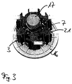
- FIG. 3 is the insulator after FIG. 2 shown with inserted pole legs 3. Clearly visible are the poles of the pole leg 3 opposite foot areas, which are provided with a dovetail 21. After the winding of the pole thighs 3, the in FIG. 3 shown package pressed into a pole ring, not shown, with corresponding guides.
- the process for producing a stator assembly for an electrical machine proceeds with the following steps. First, the pole pieces 3 are inserted into the recesses 2 of the insulating body 1, in particular a part of the insulating body 1. Then, the second part of the insulating body 1 is placed and the pole legs directly or the holders 7 wrapped with flyer coils. Finally, this package is pressed into the pole ring.
Landscapes
- Engineering & Computer Science (AREA)
- Power Engineering (AREA)
- Manufacture Of Motors, Generators (AREA)
- Insulation, Fastening Of Motor, Generator Windings (AREA)
- Motor Or Generator Frames (AREA)
- Iron Core Of Rotating Electric Machines (AREA)
Claims (15)
- Moteur électrique pour l'entraînement d'une pompe, comprenant un paquet de stator qui présente des parties saillantes de pôles (3) entourées par des enroulements de stator, les parties saillantes de pôles (3) étant entourées par une bague polaire, sur laquelle les parties saillantes de pôles (3) sont fixées de façon amovible, toutes les parties saillantes de pôles (3) étant maintenues dans un corps isolant (1) commun, qui reste après le montage des parties saillantes de pôles (3) dans le paquet de stator, caractérisé en ce que le corps isolant (1) forme un pot d'entrefer entre le stator et le rotor.
- Moteur suivant la revendication 1, caractérisé en ce que les parties saillantes de pôles (3) peuvent être respectivement assemblées avec la bague polaire, par force d'adhérence dans la direction axiale et par coopération de forme dans la direction périphérique, par l'intermédiaire d'un guidage linéaire (21) disposé dans la direction axiale, en particulier par l'intermédiaire d'un guidage en queue d'aronde.
- Moteur suivant l'une des revendications 1 et 2,
caractérisé en ce que le corps isolant (1) présente une douille entourant totalement le rotor, en particulier injectée en matière plastique. - Moteur suivant l'une des revendications précédentes, caractérisé en ce que le corps isolant (1) comporte des creux (2) pour loger les parties saillantes de pôles (3).
- Moteur suivant l'une des revendications précédentes, caractérisé en ce que le corps isolant (1) est structuré de deux semi-coques (4, 5) pouvant être assemblées dans la direction axiale.
- Moteur suivant l'une des revendications précédentes, caractérisé en ce que le corps isolant (1) présente sur son côté extérieur, opposé au rotor, des fixations (7) en forme de cadre, entourant les parties saillantes de pôles, sur lesquelles peuvent être enroulés les enroulements de stator.
- Moteur suivant la revendication 6, caractérisé en ce que le corps isolant (1) et les fixations (7) sont injectés d'une seule pièce en matière plastique.
- Moteur suivant l'une des revendications précédentes, caractérisé en ce que le corps isolant (1) présente sur un côté frontal des logements (14), dans lesquels peuvent être mis en place des raccords à borne guillotine (15) pour la mise en contact des enroulements de stator.
- Moteur suivant l'une des revendications précédentes, caractérisé en ce que le corps isolant (1) présente un support de palier (22) pour le maintien d'un palier de l'arbre.
- Moteur suivant l'une des revendications précédentes, caractérisé en ce que des enroulements de stator sont réunis en paires d'enroulements, une paire d'enroulements étant enroulée à partir d'un fil sans fin.
- Moteur suivant l'une des revendications précédentes, caractérisé en ce que les enroulements de stator sont enroulés par couches.
- Moteur suivant l'une des revendications précédentes, caractérisé en ce que les parties saillantes de pôles (3) et la bague polaire sont fabriquées par superposition de tôles individuelles dans le procédé de paquetage - découpage.
- Procédé de fabrication d'un paquet de stator pour un moteur électrique suivant les revendications 1 à 12, caractérisé en ce que- les parties saillantes de pôles (3) sont mises en place dans les creux (2) du corps isolant (1),- les parties saillantes de pôles (3) ou les fixations (7) sont guipées d'enroulements, en particulier par un enrouleur à ailettes, et- le corps isolant (1), supportant les parties saillantes de pôles (3) et les enroulements, est mis en place en maintien dans la bague polaire, le corps isolant (1) formant alors un pot d'entrefer entre le stator et le rotor.
- Procédé suivant la revendication 13, caractérisé en ce que les parties saillantes de pôles (3) sont emmanchées dans les guidages linéaires (21) de la bague polaire.
- Procédé suivant l'une des revendications 13 et 14, caractérisé en ce que les extrémités des enroulements (11) sont guidées en direction des logements (14) prévus du côté frontal et sont munies d'un raccord à borne guillotine (15).
Applications Claiming Priority (2)
| Application Number | Priority Date | Filing Date | Title |
|---|---|---|---|
| DE1999105948 DE19905948A1 (de) | 1999-02-12 | 1999-02-12 | Polschenkelträger |
| DE19905948 | 1999-02-12 |
Publications (3)
| Publication Number | Publication Date |
|---|---|
| EP1028513A2 EP1028513A2 (fr) | 2000-08-16 |
| EP1028513A3 EP1028513A3 (fr) | 2000-12-20 |
| EP1028513B1 true EP1028513B1 (fr) | 2008-05-28 |
Family
ID=7897340
Family Applications (1)
| Application Number | Title | Priority Date | Filing Date |
|---|---|---|---|
| EP20000102552 Expired - Lifetime EP1028513B1 (fr) | 1999-02-12 | 2000-02-07 | Support de pôles saillantes |
Country Status (2)
| Country | Link |
|---|---|
| EP (1) | EP1028513B1 (fr) |
| DE (2) | DE19905948A1 (fr) |
Cited By (1)
| Publication number | Priority date | Publication date | Assignee | Title |
|---|---|---|---|---|
| DE202014005789U1 (de) | 2014-07-17 | 2015-10-23 | Brose Fahrzeugteile Gmbh & Co. Kommanditgesellschaft, Coburg | Stator eines Elektromotors sowie Kontaktsystem hierfür |
Families Citing this family (3)
| Publication number | Priority date | Publication date | Assignee | Title |
|---|---|---|---|---|
| DE10212425A1 (de) * | 2002-03-21 | 2003-10-02 | Bosch Gmbh Robert | Stator für eine elektrische Maschine |
| DE50303111D1 (de) * | 2003-07-12 | 2006-06-01 | Grundfos As | Segmentierter Stator |
| DE102008019608A1 (de) * | 2008-04-18 | 2009-10-22 | Continental Automotive Gmbh | Isolationsträger für einen Stator eines Elektromotors zum Antreiben von Flüssigkeitspumpen |
Family Cites Families (7)
| Publication number | Priority date | Publication date | Assignee | Title |
|---|---|---|---|---|
| EP0064105B1 (fr) * | 1981-05-06 | 1985-10-23 | AMP INCORPORATED (a New Jersey corporation) | Stator d'un moteur électrique et son procédé de fabrication |
| GB2172444B (en) * | 1985-03-09 | 1988-08-17 | Asmo Co Ltd | Stator for an electric motor |
| DE3843477A1 (de) * | 1988-12-23 | 1990-06-28 | Oplaender Wilo Werk Gmbh | Spaltrohr-elektromotor |
| JPH0775270A (ja) * | 1993-09-03 | 1995-03-17 | Canon Electron Inc | 電磁回転機用の回転磁界発生ユニット |
| DE19740938A1 (de) * | 1997-09-17 | 1999-03-18 | Trw Fahrzeugelektrik | Stator für einen Elektromotor, insbesondere bürstenlosen Gleichstrommotor |
| DE19740937A1 (de) * | 1997-09-17 | 1999-03-18 | Trw Fahrzeugelektrik | Stator und Verfahren zum Bewickeln eines Stators für einen bürstenlosen Gleichstrommotor |
| IT1296730B1 (it) * | 1997-10-16 | 1999-07-15 | Bitron Spa | Statore per motori elettrici con rivestimento costampato elettricamente isolante. |
-
1999
- 1999-02-12 DE DE1999105948 patent/DE19905948A1/de not_active Withdrawn
-
2000
- 2000-02-07 EP EP20000102552 patent/EP1028513B1/fr not_active Expired - Lifetime
- 2000-02-07 DE DE50015176T patent/DE50015176D1/de not_active Expired - Lifetime
Cited By (2)
| Publication number | Priority date | Publication date | Assignee | Title |
|---|---|---|---|---|
| DE202014005789U1 (de) | 2014-07-17 | 2015-10-23 | Brose Fahrzeugteile Gmbh & Co. Kommanditgesellschaft, Coburg | Stator eines Elektromotors sowie Kontaktsystem hierfür |
| WO2016008827A2 (fr) | 2014-07-17 | 2016-01-21 | Brose Fahrzeugteile Gmbh & Co. Kommanditgesellschaft, Coburg | Stator d'un moteur électrique et système de contact à cet effet |
Also Published As
| Publication number | Publication date |
|---|---|
| EP1028513A2 (fr) | 2000-08-16 |
| DE19905948A1 (de) | 2000-08-17 |
| DE50015176D1 (de) | 2008-07-10 |
| EP1028513A3 (fr) | 2000-12-20 |
Similar Documents
| Publication | Publication Date | Title |
|---|---|---|
| DE112008002806B4 (de) | Drehende elektrische Maschine | |
| DE19643561C1 (de) | Elektrische Maschine mit einer Einzelpolwicklung | |
| DE10160011B4 (de) | Ständerbauweise eines Kolbenmotors | |
| DE10056555A1 (de) | Stator für dynamo-elektrische Maschinen | |
| DE102004016655A1 (de) | Stator-Baugruppe mit einem Spulenträger-Einsatz für Schlitze im Kern | |
| EP2022157A1 (fr) | Procede de fabrication d'un stator et stator correspondant | |
| DE102009010475A1 (de) | Wicklungsfixierungsbauteil und damit ausgerüstete rotierende elektrische Maschine | |
| DE69826907T2 (de) | Elektromotor | |
| WO2018192817A1 (fr) | Module de dent polaire pour une machine électrique, pièce active pourvue d'un module de dent polaire et machine électrique | |
| DE19503610C2 (de) | Mehrphasige und vielpolige, elektrisch kommutierbare Maschine und Verfahren zur Herstellung des Ständers | |
| DE102010030877A1 (de) | Steckbarer Polzahn | |
| DE102007029739A1 (de) | Stator mit Isolierung für einen Elektromotor und Isolierung für einen Stator sowie Elektrowerkzeugmaschine | |
| EP3488516B1 (fr) | Stator d'un machine à courant alternatif | |
| EP1041697B1 (fr) | Machine à réluctance avec au moins deux pôles saillants, chacun avec bobinage d'excitation et procédé de fabrication du stator d'une telle machine | |
| EP1028513B1 (fr) | Support de pôles saillantes | |
| EP1024581B1 (fr) | Connexions des enroulements d'un moteur | |
| DE102020115642B3 (de) | Elektrischer Motor und Leiterplatte | |
| DE112013001643T5 (de) | Elektrische rotierende Maschine | |
| EP1524751B1 (fr) | Moteur électrique sans balai | |
| DE102020117056A1 (de) | Bewickeltes teil für eine rotierende elektrische maschine, die für ein kraftfahrzeug bestimmt ist | |
| EP2342799B1 (fr) | Machine électrique présentant un élément de contact pour la connexion électrique de composants électriques | |
| DE102013112966A1 (de) | Elektronisch kommutierter Innenläufermotor | |
| DE69736028T2 (de) | Gerät und Verfahren zur Herstellung eines nutenlosen Stators | |
| DE4436257A1 (de) | Dynamoelektrische Maschine mit Schenkelpolläufer | |
| DE102005036108A1 (de) | Elektrische Maschine, insbesondere bürstenloser Gleichstrommotor für ein Festplattenlaufwerk |
Legal Events
| Date | Code | Title | Description |
|---|---|---|---|
| PUAI | Public reference made under article 153(3) epc to a published international application that has entered the european phase |
Free format text: ORIGINAL CODE: 0009012 |
|
| AK | Designated contracting states |
Kind code of ref document: A2 Designated state(s): DE FR GB IT |
|
| AX | Request for extension of the european patent |
Free format text: AL;LT;LV;MK;RO;SI |
|
| PUAL | Search report despatched |
Free format text: ORIGINAL CODE: 0009013 |
|
| AK | Designated contracting states |
Kind code of ref document: A3 Designated state(s): AT BE CH CY DE DK ES FI FR GB GR IE IT LI LU MC NL PT SE |
|
| AX | Request for extension of the european patent |
Free format text: AL;LT;LV;MK;RO;SI |
|
| 17P | Request for examination filed |
Effective date: 20010620 |
|
| AKX | Designation fees paid |
Free format text: DE FR GB IT |
|
| RAP1 | Party data changed (applicant data changed or rights of an application transferred) |
Owner name: WILO AG |
|
| GRAP | Despatch of communication of intention to grant a patent |
Free format text: ORIGINAL CODE: EPIDOSNIGR1 |
|
| RIN1 | Information on inventor provided before grant (corrected) |
Inventor name: SCHRECKENBERG, STEPHAN Inventor name: GENSTER, ALBERT Inventor name: KECH, HANSJUERGEN Inventor name: LUETKENHAUS, NORBERT |
|
| GRAS | Grant fee paid |
Free format text: ORIGINAL CODE: EPIDOSNIGR3 |
|
| GRAA | (expected) grant |
Free format text: ORIGINAL CODE: 0009210 |
|
| AK | Designated contracting states |
Kind code of ref document: B1 Designated state(s): DE FR GB IT |
|
| REG | Reference to a national code |
Ref country code: GB Ref legal event code: FG4D Free format text: NOT ENGLISH |
|
| REF | Corresponds to: |
Ref document number: 50015176 Country of ref document: DE Date of ref document: 20080710 Kind code of ref document: P |
|
| PLBE | No opposition filed within time limit |
Free format text: ORIGINAL CODE: 0009261 |
|
| STAA | Information on the status of an ep patent application or granted ep patent |
Free format text: STATUS: NO OPPOSITION FILED WITHIN TIME LIMIT |
|
| 26N | No opposition filed |
Effective date: 20090303 |
|
| REG | Reference to a national code |
Ref country code: FR Ref legal event code: PLFP Year of fee payment: 16 |
|
| PGFP | Annual fee paid to national office [announced via postgrant information from national office to epo] |
Ref country code: DE Payment date: 20150203 Year of fee payment: 16 Ref country code: IT Payment date: 20150213 Year of fee payment: 16 |
|
| PGFP | Annual fee paid to national office [announced via postgrant information from national office to epo] |
Ref country code: FR Payment date: 20150210 Year of fee payment: 16 Ref country code: GB Payment date: 20150204 Year of fee payment: 16 |
|
| REG | Reference to a national code |
Ref country code: DE Ref legal event code: R119 Ref document number: 50015176 Country of ref document: DE |
|
| GBPC | Gb: european patent ceased through non-payment of renewal fee |
Effective date: 20160207 |
|
| REG | Reference to a national code |
Ref country code: FR Ref legal event code: ST Effective date: 20161028 |
|
| PG25 | Lapsed in a contracting state [announced via postgrant information from national office to epo] |
Ref country code: IT Free format text: LAPSE BECAUSE OF NON-PAYMENT OF DUE FEES Effective date: 20160207 |
|
| PG25 | Lapsed in a contracting state [announced via postgrant information from national office to epo] |
Ref country code: GB Free format text: LAPSE BECAUSE OF NON-PAYMENT OF DUE FEES Effective date: 20160207 Ref country code: FR Free format text: LAPSE BECAUSE OF NON-PAYMENT OF DUE FEES Effective date: 20160229 Ref country code: DE Free format text: LAPSE BECAUSE OF NON-PAYMENT OF DUE FEES Effective date: 20160901 |