EP1027853A2 - Trennwand für eine Dusche - Google Patents
Trennwand für eine Dusche Download PDFInfo
- Publication number
- EP1027853A2 EP1027853A2 EP00100068A EP00100068A EP1027853A2 EP 1027853 A2 EP1027853 A2 EP 1027853A2 EP 00100068 A EP00100068 A EP 00100068A EP 00100068 A EP00100068 A EP 00100068A EP 1027853 A2 EP1027853 A2 EP 1027853A2
- Authority
- EP
- European Patent Office
- Prior art keywords
- partition
- fitting
- wing
- shower according
- side part
- Prior art date
- Legal status (The legal status is an assumption and is not a legal conclusion. Google has not performed a legal analysis and makes no representation as to the accuracy of the status listed.)
- Granted
Links
Images





Classifications
-
- E—FIXED CONSTRUCTIONS
- E05—LOCKS; KEYS; WINDOW OR DOOR FITTINGS; SAFES
- E05D—HINGES OR SUSPENSION DEVICES FOR DOORS, WINDOWS OR WINGS
- E05D15/00—Suspension arrangements for wings
- E05D15/06—Suspension arrangements for wings for wings sliding horizontally more or less in their own plane
- E05D15/0621—Details, e.g. suspension or supporting guides
- E05D15/0626—Details, e.g. suspension or supporting guides for wings suspended at the top
- E05D15/063—Details, e.g. suspension or supporting guides for wings suspended at the top on wheels with fixed axis
- E05D15/0634—Details, e.g. suspension or supporting guides for wings suspended at the top on wheels with fixed axis with height adjustment
-
- A—HUMAN NECESSITIES
- A47—FURNITURE; DOMESTIC ARTICLES OR APPLIANCES; COFFEE MILLS; SPICE MILLS; SUCTION CLEANERS IN GENERAL
- A47K—SANITARY EQUIPMENT; ACCESSORIES THEREFOR, e.g. TOILET ACCESSORIES
- A47K3/00—Baths; Showers; Appurtenances therefor
- A47K3/28—Showers or bathing douches
- A47K3/30—Screens or collapsible cabinets for showers or baths
- A47K3/34—Slidable screens
-
- E—FIXED CONSTRUCTIONS
- E05—LOCKS; KEYS; WINDOW OR DOOR FITTINGS; SAFES
- E05D—HINGES OR SUSPENSION DEVICES FOR DOORS, WINDOWS OR WINGS
- E05D15/00—Suspension arrangements for wings
- E05D15/06—Suspension arrangements for wings for wings sliding horizontally more or less in their own plane
- E05D15/0621—Details, e.g. suspension or supporting guides
- E05D15/0626—Details, e.g. suspension or supporting guides for wings suspended at the top
- E05D15/063—Details, e.g. suspension or supporting guides for wings suspended at the top on wheels with fixed axis
-
- E—FIXED CONSTRUCTIONS
- E05—LOCKS; KEYS; WINDOW OR DOOR FITTINGS; SAFES
- E05D—HINGES OR SUSPENSION DEVICES FOR DOORS, WINDOWS OR WINGS
- E05D15/00—Suspension arrangements for wings
- E05D15/06—Suspension arrangements for wings for wings sliding horizontally more or less in their own plane
- E05D15/0621—Details, e.g. suspension or supporting guides
- E05D15/0626—Details, e.g. suspension or supporting guides for wings suspended at the top
- E05D15/0652—Tracks
-
- E—FIXED CONSTRUCTIONS
- E05—LOCKS; KEYS; WINDOW OR DOOR FITTINGS; SAFES
- E05D—HINGES OR SUSPENSION DEVICES FOR DOORS, WINDOWS OR WINGS
- E05D5/00—Construction of single parts, e.g. the parts for attachment
- E05D5/02—Parts for attachment, e.g. flaps
- E05D5/0246—Parts for attachment, e.g. flaps for attachment to glass panels
- E05D2005/0253—Parts for attachment, e.g. flaps for attachment to glass panels the panels having conical or stepped recesses
-
- E—FIXED CONSTRUCTIONS
- E05—LOCKS; KEYS; WINDOW OR DOOR FITTINGS; SAFES
- E05D—HINGES OR SUSPENSION DEVICES FOR DOORS, WINDOWS OR WINGS
- E05D5/00—Construction of single parts, e.g. the parts for attachment
- E05D5/02—Parts for attachment, e.g. flaps
- E05D5/0246—Parts for attachment, e.g. flaps for attachment to glass panels
-
- E—FIXED CONSTRUCTIONS
- E05—LOCKS; KEYS; WINDOW OR DOOR FITTINGS; SAFES
- E05Y—INDEXING SCHEME ASSOCIATED WITH SUBCLASSES E05D AND E05F, RELATING TO CONSTRUCTION ELEMENTS, ELECTRIC CONTROL, POWER SUPPLY, POWER SIGNAL OR TRANSMISSION, USER INTERFACES, MOUNTING OR COUPLING, DETAILS, ACCESSORIES, AUXILIARY OPERATIONS NOT OTHERWISE PROVIDED FOR, APPLICATION THEREOF
- E05Y2201/00—Constructional elements; Accessories therefor
- E05Y2201/60—Suspension or transmission members; Accessories therefor
- E05Y2201/606—Accessories therefor
- E05Y2201/61—Cooperation between suspension or transmission members
- E05Y2201/612—Cooperation between suspension or transmission members between carriers and rails
- E05Y2201/614—Anti-derailing means
-
- E—FIXED CONSTRUCTIONS
- E05—LOCKS; KEYS; WINDOW OR DOOR FITTINGS; SAFES
- E05Y—INDEXING SCHEME ASSOCIATED WITH SUBCLASSES E05D AND E05F, RELATING TO CONSTRUCTION ELEMENTS, ELECTRIC CONTROL, POWER SUPPLY, POWER SIGNAL OR TRANSMISSION, USER INTERFACES, MOUNTING OR COUPLING, DETAILS, ACCESSORIES, AUXILIARY OPERATIONS NOT OTHERWISE PROVIDED FOR, APPLICATION THEREOF
- E05Y2800/00—Details, accessories and auxiliary operations not otherwise provided for
- E05Y2800/15—Applicability
- E05Y2800/16—Applicable on combinations of fixed and movable wings
-
- E—FIXED CONSTRUCTIONS
- E05—LOCKS; KEYS; WINDOW OR DOOR FITTINGS; SAFES
- E05Y—INDEXING SCHEME ASSOCIATED WITH SUBCLASSES E05D AND E05F, RELATING TO CONSTRUCTION ELEMENTS, ELECTRIC CONTROL, POWER SUPPLY, POWER SIGNAL OR TRANSMISSION, USER INTERFACES, MOUNTING OR COUPLING, DETAILS, ACCESSORIES, AUXILIARY OPERATIONS NOT OTHERWISE PROVIDED FOR, APPLICATION THEREOF
- E05Y2800/00—Details, accessories and auxiliary operations not otherwise provided for
- E05Y2800/26—Form or shape
- E05Y2800/268—Form or shape cylindrical; disc-shaped; circular
-
- E—FIXED CONSTRUCTIONS
- E05—LOCKS; KEYS; WINDOW OR DOOR FITTINGS; SAFES
- E05Y—INDEXING SCHEME ASSOCIATED WITH SUBCLASSES E05D AND E05F, RELATING TO CONSTRUCTION ELEMENTS, ELECTRIC CONTROL, POWER SUPPLY, POWER SIGNAL OR TRANSMISSION, USER INTERFACES, MOUNTING OR COUPLING, DETAILS, ACCESSORIES, AUXILIARY OPERATIONS NOT OTHERWISE PROVIDED FOR, APPLICATION THEREOF
- E05Y2800/00—Details, accessories and auxiliary operations not otherwise provided for
- E05Y2800/26—Form or shape
- E05Y2800/31—Form or shape eccentric
-
- E—FIXED CONSTRUCTIONS
- E05—LOCKS; KEYS; WINDOW OR DOOR FITTINGS; SAFES
- E05Y—INDEXING SCHEME ASSOCIATED WITH SUBCLASSES E05D AND E05F, RELATING TO CONSTRUCTION ELEMENTS, ELECTRIC CONTROL, POWER SUPPLY, POWER SIGNAL OR TRANSMISSION, USER INTERFACES, MOUNTING OR COUPLING, DETAILS, ACCESSORIES, AUXILIARY OPERATIONS NOT OTHERWISE PROVIDED FOR, APPLICATION THEREOF
- E05Y2800/00—Details, accessories and auxiliary operations not otherwise provided for
- E05Y2800/67—Materials; Strength alteration thereof
- E05Y2800/672—Glass
-
- E—FIXED CONSTRUCTIONS
- E05—LOCKS; KEYS; WINDOW OR DOOR FITTINGS; SAFES
- E05Y—INDEXING SCHEME ASSOCIATED WITH SUBCLASSES E05D AND E05F, RELATING TO CONSTRUCTION ELEMENTS, ELECTRIC CONTROL, POWER SUPPLY, POWER SIGNAL OR TRANSMISSION, USER INTERFACES, MOUNTING OR COUPLING, DETAILS, ACCESSORIES, AUXILIARY OPERATIONS NOT OTHERWISE PROVIDED FOR, APPLICATION THEREOF
- E05Y2900/00—Application of doors, windows, wings or fittings thereof
-
- E—FIXED CONSTRUCTIONS
- E05—LOCKS; KEYS; WINDOW OR DOOR FITTINGS; SAFES
- E05Y—INDEXING SCHEME ASSOCIATED WITH SUBCLASSES E05D AND E05F, RELATING TO CONSTRUCTION ELEMENTS, ELECTRIC CONTROL, POWER SUPPLY, POWER SIGNAL OR TRANSMISSION, USER INTERFACES, MOUNTING OR COUPLING, DETAILS, ACCESSORIES, AUXILIARY OPERATIONS NOT OTHERWISE PROVIDED FOR, APPLICATION THEREOF
- E05Y2900/00—Application of doors, windows, wings or fittings thereof
- E05Y2900/10—Application of doors, windows, wings or fittings thereof for buildings or parts thereof
- E05Y2900/114—Application of doors, windows, wings or fittings thereof for buildings or parts thereof for showers
Definitions
- the invention relates to a partition for a shower according to the preamble of claim 1.
- a partition for a shower according to the preamble of claim 1.
- a partition for showers has become known from EP 0 270 739 B1, where both above the fixed side panel as also a guide rod in the form above the sliding wing a round profile is present, which has a recess for receiving a carriage with idlers.
- the carriage is over a connecting element with a fitting connected to a recess has in the glass pane of the sliding wing immersed.
- the sliding wing is attached by means of conventional screw elements through the glass.
- the analog version is also the fixed side part attached, this fitting also has an incision in the end of the fixed side part is inserted.
- the fitting for the fixed side part is as comprehensive fitting on the guide rod.
- EP 0 841 032 A2 discloses a device for holding and Fastening glass panes to shower cubicles or doors Use finds. It is used to adjust the plates or glass panes to be fastened a twistable to the angle or hinge used Adjustment element proposed.
- the adjustment element has an eccentric Part related to the axis of the fastener that it by twisting allows between the glass pane and the wall make an adjustment.
- a holding part is used, which has a bore and has an annular shoulder formed against which a tension screw puts on.
- a turntable sits in one cylindrical arrangement and has lateral stops in the form of projections The stops on the outside are in the area the projections are threaded to apply a cap.
- the object of the invention is to provide a partition for showers to simplify that the fittings next to an optical attractive appearance inexpensive to manufacture and easy to are mounted, that is, there is good adjustability, at one large adjustment range. Also a good cleaning option of the glass panes may be possible.
- the sliding wing is known by means of Screw elements connected with another fitting part.
- the portable wing inside a pocket can also be used here or an incision, or it is also possible that the Wing rests on a contact surface of the fitting and by means of Connecting element with the fitting non-positively and positively connected becomes.
- the idler roller that is present at least once in the fitting is also embedded in an incision and pivoted there assembled. So that the sliding wing does not accidentally look out the guide groove of the guide profile is levered out, is a securing element available that preferably below the guide profile is inserted into the fitting of the sliding wing. This can be a pin to be screwed in, for example.
- Both the sliding wing and the sliding side part are equally high in their upper dimensions.
- the fitting for the fixed side part and the fitting for the movable wings form a circular arc, which is only of small Interruptions.
- the fittings can be used as Extruded material is produced in bar form and are made accordingly the desired width of the fittings.
- Within the fittings can have openings of various geometrical shapes Shapes exist that give the fittings a pleasing look procure. However, it is also possible that the fittings without openings be carried out.
- Hatte elements are thus inserted into the holes in the glass panes, which have a hole with respect to their center, which is eccentric is arranged to the center.
- the bore preferably has a countersink to a connecting screw or a To be able to accommodate the connecting element. Following the cut there is a through hole without thread for the connecting screw available.
- This type of attachment is firstly an inexpensive option created because only a small number of components for Attachment of a glass sheet is needed, and secondly, after the first embodiment, the distances between fixed Side part and wing should be smaller because there are no protruding caps are. This is particularly effective in showers with curved Leadership profiles. This is particularly evident in the execution of the holding element.
- a holding element of the aforementioned type can thus can be used for any type of hardware.
- FIG. 1 a partition for showers is shown, the excerpt a sliding wing 1 and a designated 2 has fixed side part. Both the wing 1 and the side part 2 have the same dimensions in height.
- the wing 1 is with a Fitting 3 and the fixed side part 2 with a fitting 24 fitted.
- the illustration in FIG. 1 shows that it is with the fittings 3 and 24 in the illustration shown and in this Position to create a harmonious, clearly defined, inexpensive Fitting acts.
- the fixed side part 2 projects with its upper end within one Incision 31 (see in particular Figure 4) in the fitting 24th inside.
- Incision 31 see in particular Figure 4
- the fitting 24 above the fixed Side part 2 connected to this non-positively and positively. Because in the reason of the incision 31 is a straight surface and this on the Top edge of the fixed side part 2 can come to rest, there is a problem-free alignment of such a fitting 24.
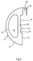
- the fitting 24 has been designed as an almost semi-spherical component and thus has a contact surface 29 on a vertical line. On the contact surface 29 is a guide profile 27 by means of screw connections 17 screwed on. Opposite the contact surface 29 there is a recess on the side 25 and a recess 30 are present to drive past easily to ensure a fitting 3 of the sliding sash.
- the fitting 24 has an outer contour 26 which is an arc follows. An opening 28 is present within the fitting 24, which is designed so that a web 36 in some areas parallel to the outer contour 26 runs.
- the sliding wing 1 is with the fitting 3 via a fastening 6 with the aid of an intermediate layer 34 positively connected. In this exemplary embodiment of FIG.
- FIG. 3 Parallel to the outer contour 4 of the fitting 3 is in the embodiment 3 shows an opening 27, so that there is a web 37 results at least over partial areas.
- the embodiment of the figure 2 shows the use of the fitting 3 described above in an analog manner Way, only in this embodiment is within the fitting 3 no breakthrough.
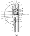
- the fixed side part 2 is not like attached in the embodiment 1 by means of a fitting 24.
- Such a holding element 42 is shown in a sectional illustration in FIG reproduced.
- the holding element 42 shows a cylindrical extension 45 on, which merges into a tapered course 46.
- a center 40 of the holding element 42 is eccentrically to this a bore 44 available, which is provided with a countersink 41.
- In the top view of the 8 also shows adjustment bores 39 to approach a tool, around the holding element 42 around its center 40 to twist, It is clear that by twisting the Holding element 42 around its center 40, the bore 44 a circular Runs course that is outside the center 40.
- the holding element 42 is not attached to its center point 40, but via the bore 44, as will be described below, does not rotate the holding element 42 around its center point 40 but rather the center of the bore 44.
- FIGS. 9 and 10 Another type of adjustment possibility is shown in FIGS. 9 and 10, in which the holding element 42 has a recess in on its upper side
- the shape of a hexagon socket 47 has a corresponding one Tool with a complementary shape can be used for adjustment can.
Landscapes
- Engineering & Computer Science (AREA)
- Mechanical Engineering (AREA)
- Health & Medical Sciences (AREA)
- Public Health (AREA)
- Epidemiology (AREA)
- General Health & Medical Sciences (AREA)
- Securing Of Glass Panes Or The Like (AREA)
- Finishing Walls (AREA)
- Support Devices For Sliding Doors (AREA)
- Specific Sealing Or Ventilating Devices For Doors And Windows (AREA)
- External Artificial Organs (AREA)
- Paper (AREA)
- Separation Using Semi-Permeable Membranes (AREA)
- Bathtubs, Showers, And Their Attachments (AREA)
Abstract
Description
- Figur 1:
- Einen Ausschnitt einer Trennwand für Duschen mit aufliegenden Beschlägen im oberen Bereich.
- Figur 2:
- Ein weiteres Ausführungsbeipspiel.
- Figur 3:
- Einen Beschlag für den verschiebbaren Flügel in der Draufsicht.
- Figur 4:
- Einen Beschlag für ein feststehendes Seitenteil in der Draufsicht.
- Figur 5:
- Einen Ausschnitt einer Trennwand für Duschen mit aufliegenden Beschlagen im oberen Bereich, jedoch mit einem eingelassenen Halteteil.
- Figur 6:
- Ein weiteres Ausführungsbeipspiel, jedoch mit einem eingelassenen Halteteil.
- Figur 7:
- Ein Halteelement im Schnitt in der Seitenansicht.
- Figur 8:
- Ein Halteelement nach Figur 7 in der Draufsicht
- Figur 9:
- Eine weitere Ausführung eines Halteelementes im Schnitt in der Seitenansicht.
- Figur 10:
- Ein Halteelement nach Figur 9 in der Draufsicht.
- 1
- Flügel
- 2
- feststehendes Seitenteil
- 3
- Beschlag
- 4
- Außenkontur
- 5
- Antagefläche
- 6
- Befestigung
- 7
- Führungsprofil
- 8
- Sicherung
- 9
- Bohrung
- 10
- Einsatz
- 11
- Ansatz
- 12
- Kappe
- 13
- Rücksprung
- 14
- Vorsprung
- 15
- Zwischenstück
- 16
- Bohrung
- 17
- Befestigung
- 18
- Führungsnut
- 19
- Rücksprung
- 20
- Tragrolle
- 21
- Vorsprung
- 22
- Einschnitt
- 23
- Rollenlagerung/Befestigung
- 24
- Beschlag
- 25
- Rücksprung
- 26
- Außenkontur
- 27
- Durchbruch
- 28
- Durchbruch
- 29
- Anlagefläche
- 30
- Rücksprung
- 31
- Einschnitt
- 32
- Schenkel
- 33
- Druckschrauben
- 34
- Zwischenlage
- 35
- Bohrung
- 36
- Steg
- 37
- Steg
- 38
- Steg
- 39
- Verstellbohrung
- 40
- Mittelpunkt
- 41
- Senkung
- 42
- Halteelement
- 43
- Verbindungsschraube
- 44
- Bohrung
- 45
- zylindrischer Ansatz
- 46
- kegeliger Verlauf
- 47
- Innensechskant
Claims (15)
- Trennwand für eine Dusche mit wenigstens einem feststehenden Seitenteil (2) und wenigstens einem an einem Führungsprofil (7) mittels Tragrollen (20) verschiebbaren Flügel (1), dadurch gekennzeichnet, daß das Führungsprofil (7) mittels eines Beschlages (24) in senkrechter Flucht über den Flügel (1) angebracht ist, wobei der Beschlag (24) mittels eines Einschnittes (31) über den oberen Bereich des feststehenden Seitenteiles (2) gesetzt wird, mit diesem befestigt ist und der Flügel (1) über einen Beschlag (3), an dem die Tragrolle (20) in einem Einschnitt (22) drehgelagert ist, in dem rechteckigen mit wenigstens einer Führungsnut (18) ausgestatteten Führungsprofil (7) verschiebbar ist und das Seitenteil (2) und der Flügel (1) gleich hoch sind.
- Trennwand für eine Dusche nach Anspruch 1, dadurch gekennzeichnet, daß das Führungsprofil mittels eines Zwischenstückes (15) an dem Seitenteil (2) in senkrechter Flucht über den Flügel (1) angebracht ist, wobei das oberer Ende des Seitenteiles über das obere Ende des Flügels (1) so weit hinausragt, daß es mit der Oberkante des Beschlages (3) anschließt.
- Trennwand für eine Dusche nach Anspruch 1 und 2, dadurch gekennzeichnet, daß die Beschläge (3) und (24) eine Außenkontur (4) und (26) aufweisen, die Teil eines Kreisbogens sind.
- Trennwand für eine Dusche nach Anspruch 3, dadurch gekennzeichnet, daß der Beschlag (3) einen Durchbruch (27) und der Beschlag (24) einen Durchbruch (28) aufweist.
- Trennwand für eine Dusche nach Anspruch 1, dadurch gekennzeichnet, daß der Beschlag (3) in Flucht mit dem Einschnitt (22) eine Anlagefläche (5) für den Flügel (1) aufweist.
- Trennwand für eine Dusche nach Anspruch 5, dadurch gekennzeichnet, daß zwischen Einschnitt (22) und der Anlagefläche (5) mindestens ein Rücksprung (13) oder (19) vorhanden ist.
- Trennwand für eine Dusche nach Anspruch 6, dadurch gekennzeichnet, daß innerhalb der Rücksprünge (13, 19) ein Vorsprung (14) angeformt ist, in dem eine Sicherung zur unbewußten Aushebung des Flügels (1) angebracht ist.
- Trennwand für eine Dusche nach Anspruch 1, 3 und 4, dadurch gekennzeichnet, daß das Führungsprofil (7) an einer Anlagefläche (29) des Beschlages (24) angebracht ist und gegenüber der Anlagefläche (29) Rücksprünge (25) und (30) vorhanden sind.
- Trennwand für eine Dusche nach Anspruch 1 und 2, dadurch gekennzeichnet, daß der Flügel (1) und das feststehende Seitenteil (2) über justierbare in die Glasscheiben in jeweils einer Bohrung bündig eingelassene Halteelemente (42), welche mit den Beschlägen (3, 24) kraft- und formschlüssig verbunden sind.
- Trennwand für eine Dusche nach Anspruch 9, dadurch gekennzeichnet, daß das Halteelement (42) mit einer exzentrisch zu einem Mittelpunkt (40) des Halteelementes (42) liegenden Bohrung (44) versehen ist, die von einer Verbindungsschraube (43) durchdrungen wird und daß eine Angriffsmöglichkeit für den Einsatz eines Werkzeuges zur Verdrehung des Halteelementes (42) gegeben ist.
- Trennwand für eine Dusche nach Anspruch 10, dadurch gekennzeichnet, daß die Verbindungsschraube (43) eine Senkkopfschraube ist, deren Kopf bündig mit dem Halteelement (42) abschließt.
- Trennwand für eine Dusche nach Anspruch 10, dadurch gekennzeichnet, daß das Halteelement (42) stufenlos in der Glasbohrung verdreht werden kann.
- Trennwand für eine Dusche nach Anspruch 12, dadurch gekennzeichnet, daß zur Verdrehung des Halteelementes (42) Verstellbohrungen (39) vorhanden sind.
- Trennwand für eine Dusche nach Anspruch 12, dadurch gekennzeichnet, daß zur Verdrehung des Halteelementes (42) ein eingelassener Innensechskant (47) vorhanden ist.
- Trennwand für eine Dusche nach einem oder mehreren der vorhergehenden Ansprüche, dadurch gekennzeichnet, daß die Beschläge (3) und (24) aus einem stranggepressten Leichtmetallprofil bestehen.
Applications Claiming Priority (4)
| Application Number | Priority Date | Filing Date | Title |
|---|---|---|---|
| DE19905474 | 1999-02-10 | ||
| DE19905474A DE19905474A1 (de) | 1999-02-10 | 1999-02-10 | Trennwand für eine Dusche |
| DE19943568 | 1999-09-13 | ||
| DE19943568 | 1999-09-13 |
Publications (3)
| Publication Number | Publication Date |
|---|---|
| EP1027853A2 true EP1027853A2 (de) | 2000-08-16 |
| EP1027853A3 EP1027853A3 (de) | 2002-02-13 |
| EP1027853B1 EP1027853B1 (de) | 2006-07-26 |
Family
ID=26051771
Family Applications (1)
| Application Number | Title | Priority Date | Filing Date |
|---|---|---|---|
| EP00100068A Expired - Lifetime EP1027853B1 (de) | 1999-02-10 | 2000-01-05 | Trennwand für eine Dusche |
Country Status (4)
| Country | Link |
|---|---|
| EP (1) | EP1027853B1 (de) |
| AT (1) | ATE333827T1 (de) |
| DE (1) | DE50013206D1 (de) |
| ES (1) | ES2269026T3 (de) |
Cited By (1)
| Publication number | Priority date | Publication date | Assignee | Title |
|---|---|---|---|---|
| EP1810602A3 (de) * | 2000-10-27 | 2009-05-06 | Dorma Gmbh & Co. Kg | Beschlag zur Befestigung von Glasscheiben |
Citations (2)
| Publication number | Priority date | Publication date | Assignee | Title |
|---|---|---|---|---|
| EP0270739B1 (de) | 1986-11-22 | 1991-07-17 | Paul-Jean Munch | Trennwand für Dusche |
| EP0841032A2 (de) | 1996-11-12 | 1998-05-13 | Joachim Fischbach | Vorrichtung zur justierbaren Halterung von Platten, insbesondere von Glasscheiben oder dergleichen |
Family Cites Families (4)
| Publication number | Priority date | Publication date | Assignee | Title |
|---|---|---|---|---|
| DE3105277C2 (de) * | 1981-02-13 | 1989-02-23 | Paul-Jean 7816 Münstertal Munch | Trennwand für Dusche |
| DE3238204A1 (de) * | 1982-10-15 | 1984-04-19 | Pauli & Sohn GmbH Metallwaren, 5220 Waldbröl | Vorrichtung zur haengenden anbringung von scheiben an einer laufschiene |
| DE4308413A1 (de) * | 1993-03-17 | 1994-09-22 | Paul Jean Munch | Trennwand für Dusche mit einer Schiebetüre |
| DE29808586U1 (de) * | 1998-05-13 | 1998-07-23 | Dorma Gmbh + Co. Kg, 58256 Ennepetal | Duschabtrennung |
-
2000
- 2000-01-05 DE DE50013206T patent/DE50013206D1/de not_active Expired - Fee Related
- 2000-01-05 ES ES00100068T patent/ES2269026T3/es not_active Expired - Lifetime
- 2000-01-05 AT AT00100068T patent/ATE333827T1/de not_active IP Right Cessation
- 2000-01-05 EP EP00100068A patent/EP1027853B1/de not_active Expired - Lifetime
Patent Citations (2)
| Publication number | Priority date | Publication date | Assignee | Title |
|---|---|---|---|---|
| EP0270739B1 (de) | 1986-11-22 | 1991-07-17 | Paul-Jean Munch | Trennwand für Dusche |
| EP0841032A2 (de) | 1996-11-12 | 1998-05-13 | Joachim Fischbach | Vorrichtung zur justierbaren Halterung von Platten, insbesondere von Glasscheiben oder dergleichen |
Cited By (1)
| Publication number | Priority date | Publication date | Assignee | Title |
|---|---|---|---|---|
| EP1810602A3 (de) * | 2000-10-27 | 2009-05-06 | Dorma Gmbh & Co. Kg | Beschlag zur Befestigung von Glasscheiben |
Also Published As
| Publication number | Publication date |
|---|---|
| ATE333827T1 (de) | 2006-08-15 |
| EP1027853B1 (de) | 2006-07-26 |
| EP1027853A3 (de) | 2002-02-13 |
| ES2269026T3 (es) | 2007-04-01 |
| DE50013206D1 (de) | 2006-09-07 |
Similar Documents
| Publication | Publication Date | Title |
|---|---|---|
| EP1040781B1 (de) | Duschabtrennung | |
| DE10021330A1 (de) | Verstellbare Scharnier-Rahmen-Anordnung | |
| EP1020154A2 (de) | Duschabtrennung | |
| EP1201171A1 (de) | Beschlag zur Befestigung von Glasscheiben | |
| DE29511756U1 (de) | Flügelseitiges Ecklagerbeschlagteil für Drehkippfenster | |
| DE3104973A1 (de) | "aufschraubband, insbesondere fuer schwere fenster- oder tuerfluegel mit kunststoffprofilen" | |
| EP0318422B1 (de) | Einstellbares Gelenkband, insbesondere für Fenster und Türen | |
| WO2009089883A1 (de) | Ecklager für ein fenster, eine tür oder dergleichen | |
| DE2524268C3 (de) | Scharnier für Profil- oder Rohrrahmen von Türen o.dgl | |
| EP0939186A1 (de) | Band für Türen, Fenster und dergleichen | |
| EP1120520B1 (de) | Türblatt mit Beschlag | |
| DE19943567C2 (de) | Befestigungsvorrichtung für eine Duschabtrennung | |
| DE10148935A1 (de) | Beschlag für Schiebetüren | |
| DE2758333C2 (de) | Beschlag für Flügel von Fenstern, Türen o.dgl., insbesondere Drehkipp- Flügel | |
| EP0487825B1 (de) | Verdeckt angeordneter Beschlag für Drehflügel, insb. für Dreh-Kipp-Flügel von Fenstern oder Türen | |
| DE19949057C2 (de) | Befestigungsvorrichtung für eine Duschabtrennung | |
| EP1027853B1 (de) | Trennwand für eine Dusche | |
| DE102007025857A1 (de) | Gelenkband für Türen oder Fenster | |
| DE29923347U1 (de) | Befestigungsvorrichtung für eine Duschabtrennung | |
| EP1560996A1 (de) | Beschlaganordnung für glastüren | |
| DE3010706A1 (de) | Gansglasfluegel-beschlag | |
| EP1054126A1 (de) | Laufschuh eines Parallelschiebe- und Kippbeschlages | |
| DE3515416A1 (de) | Scharnier fuer tueren mit ueberschlag | |
| DE2759387C1 (de) | Beschlag fuer Fluegel von Fenstern,Tueren oder dergleichen,insbesondere Drehkippfluegel | |
| DE4435540C2 (de) | Scharnierband |
Legal Events
| Date | Code | Title | Description |
|---|---|---|---|
| PUAI | Public reference made under article 153(3) epc to a published international application that has entered the european phase |
Free format text: ORIGINAL CODE: 0009012 |
|
| AK | Designated contracting states |
Kind code of ref document: A2 Designated state(s): AT BE CH CY DE DK ES FI FR GB GR IE IT LI LU MC NL PT SE |
|
| AX | Request for extension of the european patent |
Free format text: AL;LT;LV;MK;RO;SI |
|
| PUAL | Search report despatched |
Free format text: ORIGINAL CODE: 0009013 |
|
| AK | Designated contracting states |
Kind code of ref document: A3 Designated state(s): AT BE CH CY DE DK ES FI FR GB GR IE IT LI LU MC NL PT SE |
|
| AX | Request for extension of the european patent |
Free format text: AL;LT;LV;MK;RO;SI |
|
| RIC1 | Information provided on ipc code assigned before grant |
Free format text: 7A 47K 3/34 A, 7E 05D 15/06 B |
|
| 17P | Request for examination filed |
Effective date: 20020813 |
|
| AKX | Designation fees paid |
Free format text: AT BE CH CY DE DK ES FI FR GB GR IE IT LI LU MC NL PT SE |
|
| 17Q | First examination report despatched |
Effective date: 20040722 |
|
| GRAP | Despatch of communication of intention to grant a patent |
Free format text: ORIGINAL CODE: EPIDOSNIGR1 |
|
| GRAS | Grant fee paid |
Free format text: ORIGINAL CODE: EPIDOSNIGR3 |
|
| GRAA | (expected) grant |
Free format text: ORIGINAL CODE: 0009210 |
|
| AK | Designated contracting states |
Kind code of ref document: B1 Designated state(s): AT BE CH CY DE DK ES FI FR GB GR IE IT LI LU MC NL PT SE |
|
| PG25 | Lapsed in a contracting state [announced via postgrant information from national office to epo] |
Ref country code: IT Free format text: LAPSE BECAUSE OF FAILURE TO SUBMIT A TRANSLATION OF THE DESCRIPTION OR TO PAY THE FEE WITHIN THE PRESCRIBED TIME-LIMIT;WARNING: LAPSES OF ITALIAN PATENTS WITH EFFECTIVE DATE BEFORE 2007 MAY HAVE OCCURRED AT ANY TIME BEFORE 2007. THE CORRECT EFFECTIVE DATE MAY BE DIFFERENT FROM THE ONE RECORDED. Effective date: 20060726 Ref country code: FI Free format text: LAPSE BECAUSE OF FAILURE TO SUBMIT A TRANSLATION OF THE DESCRIPTION OR TO PAY THE FEE WITHIN THE PRESCRIBED TIME-LIMIT Effective date: 20060726 Ref country code: IE Free format text: LAPSE BECAUSE OF FAILURE TO SUBMIT A TRANSLATION OF THE DESCRIPTION OR TO PAY THE FEE WITHIN THE PRESCRIBED TIME-LIMIT Effective date: 20060726 |
|
| REG | Reference to a national code |
Ref country code: GB Ref legal event code: FG4D Free format text: NOT ENGLISH |
|
| REG | Reference to a national code |
Ref country code: CH Ref legal event code: EP |
|
| REG | Reference to a national code |
Ref country code: IE Ref legal event code: FG4D Free format text: LANGUAGE OF EP DOCUMENT: GERMAN |
|
| REF | Corresponds to: |
Ref document number: 50013206 Country of ref document: DE Date of ref document: 20060907 Kind code of ref document: P |
|
| PG25 | Lapsed in a contracting state [announced via postgrant information from national office to epo] |
Ref country code: DK Free format text: LAPSE BECAUSE OF FAILURE TO SUBMIT A TRANSLATION OF THE DESCRIPTION OR TO PAY THE FEE WITHIN THE PRESCRIBED TIME-LIMIT Effective date: 20061026 Ref country code: SE Free format text: LAPSE BECAUSE OF FAILURE TO SUBMIT A TRANSLATION OF THE DESCRIPTION OR TO PAY THE FEE WITHIN THE PRESCRIBED TIME-LIMIT Effective date: 20061026 |
|
| GBT | Gb: translation of ep patent filed (gb section 77(6)(a)/1977) |
Effective date: 20061027 |
|
| PG25 | Lapsed in a contracting state [announced via postgrant information from national office to epo] |
Ref country code: PT Free format text: LAPSE BECAUSE OF FAILURE TO SUBMIT A TRANSLATION OF THE DESCRIPTION OR TO PAY THE FEE WITHIN THE PRESCRIBED TIME-LIMIT Effective date: 20061226 |
|
| PGFP | Annual fee paid to national office [announced via postgrant information from national office to epo] |
Ref country code: NL Payment date: 20070109 Year of fee payment: 8 |
|
| PGFP | Annual fee paid to national office [announced via postgrant information from national office to epo] |
Ref country code: DE Payment date: 20070110 Year of fee payment: 8 |
|
| PGFP | Annual fee paid to national office [announced via postgrant information from national office to epo] |
Ref country code: AT Payment date: 20070111 Year of fee payment: 8 |
|
| PGFP | Annual fee paid to national office [announced via postgrant information from national office to epo] |
Ref country code: GB Payment date: 20070119 Year of fee payment: 8 |
|
| PGFP | Annual fee paid to national office [announced via postgrant information from national office to epo] |
Ref country code: ES Payment date: 20070130 Year of fee payment: 8 |
|
| PG25 | Lapsed in a contracting state [announced via postgrant information from national office to epo] |
Ref country code: CH Free format text: LAPSE BECAUSE OF NON-PAYMENT OF DUE FEES Effective date: 20070131 Ref country code: LI Free format text: LAPSE BECAUSE OF NON-PAYMENT OF DUE FEES Effective date: 20070131 Ref country code: MC Free format text: LAPSE BECAUSE OF NON-PAYMENT OF DUE FEES Effective date: 20070131 |
|
| ET | Fr: translation filed | ||
| REG | Reference to a national code |
Ref country code: ES Ref legal event code: FG2A Ref document number: 2269026 Country of ref document: ES Kind code of ref document: T3 |
|
| PLBE | No opposition filed within time limit |
Free format text: ORIGINAL CODE: 0009261 |
|
| STAA | Information on the status of an ep patent application or granted ep patent |
Free format text: STATUS: NO OPPOSITION FILED WITHIN TIME LIMIT |
|
| 26N | No opposition filed |
Effective date: 20070427 |
|
| REG | Reference to a national code |
Ref country code: CH Ref legal event code: PL |
|
| BERE | Be: lapsed |
Owner name: DORMA G.M.B.H. + CO. KG Effective date: 20070131 |
|
| PG25 | Lapsed in a contracting state [announced via postgrant information from national office to epo] |
Ref country code: BE Free format text: LAPSE BECAUSE OF NON-PAYMENT OF DUE FEES Effective date: 20070131 |
|
| PGFP | Annual fee paid to national office [announced via postgrant information from national office to epo] |
Ref country code: IT Payment date: 20070623 Year of fee payment: 8 |
|
| PG25 | Lapsed in a contracting state [announced via postgrant information from national office to epo] |
Ref country code: GR Free format text: LAPSE BECAUSE OF FAILURE TO SUBMIT A TRANSLATION OF THE DESCRIPTION OR TO PAY THE FEE WITHIN THE PRESCRIBED TIME-LIMIT Effective date: 20061027 |
|
| PGFP | Annual fee paid to national office [announced via postgrant information from national office to epo] |
Ref country code: FR Payment date: 20070111 Year of fee payment: 8 |
|
| GBPC | Gb: european patent ceased through non-payment of renewal fee |
Effective date: 20080105 |
|
| NLV4 | Nl: lapsed or anulled due to non-payment of the annual fee |
Effective date: 20080801 |
|
| PG25 | Lapsed in a contracting state [announced via postgrant information from national office to epo] |
Ref country code: DE Free format text: LAPSE BECAUSE OF NON-PAYMENT OF DUE FEES Effective date: 20080801 Ref country code: NL Free format text: LAPSE BECAUSE OF NON-PAYMENT OF DUE FEES Effective date: 20080801 |
|
| PG25 | Lapsed in a contracting state [announced via postgrant information from national office to epo] |
Ref country code: AT Free format text: LAPSE BECAUSE OF NON-PAYMENT OF DUE FEES Effective date: 20080105 |
|
| REG | Reference to a national code |
Ref country code: FR Ref legal event code: ST Effective date: 20081029 |
|
| PG25 | Lapsed in a contracting state [announced via postgrant information from national office to epo] |
Ref country code: GB Free format text: LAPSE BECAUSE OF NON-PAYMENT OF DUE FEES Effective date: 20080105 |
|
| REG | Reference to a national code |
Ref country code: ES Ref legal event code: FD2A Effective date: 20080108 |
|
| PG25 | Lapsed in a contracting state [announced via postgrant information from national office to epo] |
Ref country code: FR Free format text: LAPSE BECAUSE OF NON-PAYMENT OF DUE FEES Effective date: 20080131 |
|
| PG25 | Lapsed in a contracting state [announced via postgrant information from national office to epo] |
Ref country code: ES Free format text: LAPSE BECAUSE OF NON-PAYMENT OF DUE FEES Effective date: 20080108 |
|
| PG25 | Lapsed in a contracting state [announced via postgrant information from national office to epo] |
Ref country code: IT Free format text: LAPSE BECAUSE OF NON-PAYMENT OF DUE FEES Effective date: 20080105 Ref country code: CY Free format text: LAPSE BECAUSE OF FAILURE TO SUBMIT A TRANSLATION OF THE DESCRIPTION OR TO PAY THE FEE WITHIN THE PRESCRIBED TIME-LIMIT Effective date: 20060726 Ref country code: LU Free format text: LAPSE BECAUSE OF NON-PAYMENT OF DUE FEES Effective date: 20070105 |