EP1027200B1 - Injection mold for insert-molding a synthetic material around a filter material, filter for the filtration of fluids and method for producing such filter - Google Patents
Injection mold for insert-molding a synthetic material around a filter material, filter for the filtration of fluids and method for producing such filter Download PDFInfo
- Publication number
- EP1027200B1 EP1027200B1 EP98953293A EP98953293A EP1027200B1 EP 1027200 B1 EP1027200 B1 EP 1027200B1 EP 98953293 A EP98953293 A EP 98953293A EP 98953293 A EP98953293 A EP 98953293A EP 1027200 B1 EP1027200 B1 EP 1027200B1
- Authority
- EP
- European Patent Office
- Prior art keywords
- filter
- space
- filter material
- molding
- edge
- Prior art date
- Legal status (The legal status is an assumption and is not a legal conclusion. Google has not performed a legal analysis and makes no representation as to the accuracy of the status listed.)
- Expired - Lifetime
Links
- 239000000463 material Substances 0.000 title claims abstract description 119
- 238000000465 moulding Methods 0.000 title claims abstract description 83
- 229920002994 synthetic fiber Polymers 0.000 title claims abstract description 67
- 238000002347 injection Methods 0.000 title claims abstract description 62
- 239000007924 injection Substances 0.000 title claims abstract description 62
- 238000001914 filtration Methods 0.000 title claims description 14
- 239000012530 fluid Substances 0.000 title claims description 10
- 238000004519 manufacturing process Methods 0.000 title claims description 6
- OKTJSMMVPCPJKN-UHFFFAOYSA-N Carbon Chemical compound [C] OKTJSMMVPCPJKN-UHFFFAOYSA-N 0.000 claims abstract description 38
- 229910052799 carbon Inorganic materials 0.000 claims abstract description 38
- 230000007704 transition Effects 0.000 claims abstract description 32
- 239000002245 particle Substances 0.000 claims abstract description 30
- 238000000034 method Methods 0.000 claims description 7
- 230000009969 flowable effect Effects 0.000 claims 1
- 238000001746 injection moulding Methods 0.000 claims 1
- 230000008569 process Effects 0.000 description 5
- 238000007789 sealing Methods 0.000 description 3
- 239000004743 Polypropylene Substances 0.000 description 2
- 230000000694 effects Effects 0.000 description 2
- -1 polypropylene Polymers 0.000 description 2
- 229920001155 polypropylene Polymers 0.000 description 2
- 238000003825 pressing Methods 0.000 description 2
- 239000011347 resin Substances 0.000 description 2
- 229920005989 resin Polymers 0.000 description 2
- 239000012209 synthetic fiber Substances 0.000 description 2
- 238000005406 washing Methods 0.000 description 2
- 230000004888 barrier function Effects 0.000 description 1
- 230000008901 benefit Effects 0.000 description 1
- 238000004140 cleaning Methods 0.000 description 1
- 230000003247 decreasing effect Effects 0.000 description 1
- 230000001877 deodorizing effect Effects 0.000 description 1
- 238000005516 engineering process Methods 0.000 description 1
- 230000002349 favourable effect Effects 0.000 description 1
- 239000000835 fiber Substances 0.000 description 1
- 239000007788 liquid Substances 0.000 description 1
- 239000000203 mixture Substances 0.000 description 1
- 230000009467 reduction Effects 0.000 description 1
- 239000000126 substance Substances 0.000 description 1
Images

Classifications
-
- B—PERFORMING OPERATIONS; TRANSPORTING
- B29—WORKING OF PLASTICS; WORKING OF SUBSTANCES IN A PLASTIC STATE IN GENERAL
- B29C—SHAPING OR JOINING OF PLASTICS; SHAPING OF MATERIAL IN A PLASTIC STATE, NOT OTHERWISE PROVIDED FOR; AFTER-TREATMENT OF THE SHAPED PRODUCTS, e.g. REPAIRING
- B29C45/00—Injection moulding, i.e. forcing the required volume of moulding material through a nozzle into a closed mould; Apparatus therefor
- B29C45/14—Injection moulding, i.e. forcing the required volume of moulding material through a nozzle into a closed mould; Apparatus therefor incorporating preformed parts or layers, e.g. injection moulding around inserts or for coating articles
- B29C45/14336—Coating a portion of the article, e.g. the edge of the article
- B29C45/14418—Sealing means between mould and article
-
- B—PERFORMING OPERATIONS; TRANSPORTING
- B29—WORKING OF PLASTICS; WORKING OF SUBSTANCES IN A PLASTIC STATE IN GENERAL
- B29C—SHAPING OR JOINING OF PLASTICS; SHAPING OF MATERIAL IN A PLASTIC STATE, NOT OTHERWISE PROVIDED FOR; AFTER-TREATMENT OF THE SHAPED PRODUCTS, e.g. REPAIRING
- B29C45/00—Injection moulding, i.e. forcing the required volume of moulding material through a nozzle into a closed mould; Apparatus therefor
- B29C45/14—Injection moulding, i.e. forcing the required volume of moulding material through a nozzle into a closed mould; Apparatus therefor incorporating preformed parts or layers, e.g. injection moulding around inserts or for coating articles
- B29C2045/1486—Details, accessories and auxiliary operations
- B29C2045/14934—Preventing penetration of injected material between insert and adjacent mould wall
-
- B—PERFORMING OPERATIONS; TRANSPORTING
- B29—WORKING OF PLASTICS; WORKING OF SUBSTANCES IN A PLASTIC STATE IN GENERAL
- B29L—INDEXING SCHEME ASSOCIATED WITH SUBCLASS B29C, RELATING TO PARTICULAR ARTICLES
- B29L2016/00—Articles with corrugations or pleats
-
- B—PERFORMING OPERATIONS; TRANSPORTING
- B29—WORKING OF PLASTICS; WORKING OF SUBSTANCES IN A PLASTIC STATE IN GENERAL
- B29L—INDEXING SCHEME ASSOCIATED WITH SUBCLASS B29C, RELATING TO PARTICULAR ARTICLES
- B29L2031/00—Other particular articles
- B29L2031/14—Filters
Definitions
- the present invention relates to an injection mold for insert-molding a synthetic material around the edge of a filter material used particularly for the filtration of air streaming into the interior of a motor vehicle. Further, the invention relates to a method for producing a filter for the filtration of fluids, as used particularly in vehicles. Finally, the invention relates to a filter for the filtration of fluids.
- filter materials which, in addition to at least one particle filter layer, also comprise an active carbon layer of active carbon particles.
- filter materials of the filters are connected - at least along parts of their edges - to stiffening elements which are particularly provided as frames surrounding the edge of the filter material.
- Such frames or stiffening elements fulfill a holding function because, if the filter material is folded into a zig-zag shape for enlarging the filter surface, they will maintain the corrugated structure of the filter surface.
- the attachment of stiffening elements or a continuous frame to a filter material is realized in a cost-saving manner by molding a synthetic material around the filter material.
- the filter material is inserted into an injection mold, with the edge of the filter material projecting into a molding space of the injection mold and the rest of the filter material being arranged in a receiving space of the injection mold.
- the injection mold must be in sealing abutment on the filter material so that no fluid connection between the molding space and the receiving space exists for the viscous synthetic material.
- Such a sealing abutment in the prior art is realized by pressing the filter material between the outer wall of a projection on one member of the mold and the outer wall of a projection of another member of the mold, such that when molten resin is then injected into the mold, resin fills the molding space and does not pass into the constricted portion formed between the two projections of the mold.
- the molding of synthetic material around a filter material is difficult particularly if, due to the structure of the filter material, a tightly sealed closure between the molding space and the receiving space can be realized not at all or only by extreme pressure forces acting on the filter material.
- the filter material in addition to a particle filter layer, also comprises an active carbon layer of active carbon particles or has porous properties.
- the porous structure of an active carbon layer requires the application of relatively high press-on forces which, in the region between the molding space and the receiving space, are exerted by the injection mold onto the filter material to thus squeeze off the filter material, as it were. These high force cause considerable wear of the injection mold so that the cost-saving effects obtainable by the molding technology are partially neutralized due to increased expenses for injection molds.
- the instant invention provides an injection mold for insert-molding a synthetic material around the edge of a filter material, in particular a filter material comprising at least one particle filter layer and at least one active carbon layer of active carbon particles, said injection mold being defined according to claim 1. Moreover, the invention provides a method for producing a filter as defined in claim 6.
- the injection mold of the invention comprises two mold halves which, in the closed condition, form a receiving space for the filter material, a molding space for forming the synthetic material to be molded around the edge of the filter material, and a transition space between the receiving space and the molding space.
- the filter material to be subjected to insert molding is placed into the receiving space, with the edge portion of the filter material extending through the transition space up to the molding space.
- the actual edge of the filter material projects from the transition space into the molding space.
- a constricted portion formed by the walls of the two mold halves; within this constricted portion, the mold walls of the mold halves are arranged in fluid-tight abutment on the filter material when the latter has been inserted.
- the constricted portion of the transition space comprises at least two narrowed portions and a widened portion arranged therebetween.
- the distance of the mold walls of the two mold halves is smaller than in the widened portion.
- the at least two narrowed portions which are arranged transversely to that direction of the transition space which is oriented between the molding space and the receiving space and, when viewed along the direction of the transition space are arranged behind each other between the molding space and the receiving space, act like two barriers for preventing the intrusion of viscous synthetic material from the molding space into the receiving space.
- the widened portion arranged between respectively two narrowed portions serves for accommodating filter material which has been laterally displaced due to squeezing in the narrowed portions.
- active carbon particles in as far as they are not decreased in size when squeezing the filter material
- the widened portion or each of the plurality of widened portions functions like a dead volume for receiving viscous synthetic material which, during the molding process performed on the edge of the filter material passes through the narrowed portion on the side of the molding space.
- a highly reliable production with an almost negligible percentage of rejects is realized by providing the constricted portion of the transition space with three narrowed portions with intermediate widened portions, with the narrowed portions and the widened portions being arranged alternately in that direction of the transition space which is oriented between the molding space and the receiving space.
- the molding space is provided with at least one constricted portion dividing the molding space into a first partial. space and a second partial space.
- This constricted portion of the molding space increases the flow resistance to the injected synthetic material.
- the edge of the filter material projects into that partial space of the molding space which follows the transition space, and the injection channel or the injection channels for injecting the synthetic material into the molding space enter into the other partial space of the molding space.
- the front of the viscous synthetic material passes the constricted portion to enter the other partial space of the molding space which has the edge of the filter material projecting thereinto.
- the synthetic material will primarily flow from the partial space comprising the injection channels into the partial space receiving the edge of the filter material, instead of flowing in the reverse direction.
- a "washing out" of the edge of the filter material i.e. a detachment of active carbon particles from the edge of the filter material, is largely prevented, which has a favorable effect for the design of the finished filter because no or nearly no active carbon particles will penetrate into the synthetic-material element molded around the filter material.
- the injection mold of the invention is particularly suited for insert molding a synthetic material around filter materials which comprise an active carbon layer of active carbon particles arranged between two nonwoven layers.
- one of the two nonwoven layers functions as a particle filter layer and is preferably formed from an electret material.
- This electret material preferably comprises synthetic fibers of polypropylene which have been given electret properties. While that layer of the filter material which serves as a particle filter layer is arranged before the active carbon layer when viewed in the flow direction, the second nonwoven layer is arranged behind the active carbon layer and is particularly provided to keep the active carbon particles from being detached and carried along with the fluid flow to be filtered.
- An inventive filter for the filtration of fluids provided with a synthetic material therearound by an insert molding process using the inventive injection mold, comprises the features of claim 7.
- the inventive filter is distinguished particularly by the provision of two deepened grooves in the frame-side region of the filter material, with a rib formed between the two deepened grooves.
- the at least two deepened grooves and the rib arranged therebetween are arranged substantially in parallel to the direction of at least one portion of the (synthetic) frame (attached by insert molding).
- the filter in the frame-side region of its filter material comprises a plurality of deepened grooves with respective ribs arranged therebetween.
- the frame has a reduced thickness in the region of the embedded edge of the filter material. This narrowed portion of the frame corresponds to the narrowed portion of the molding space of the injection mold that has been used for producing the inventive filter.
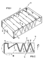
- Fig. 1 shows a perspective view of a filter comprising a filter material with two non-woven layers and an active carbon layer arranged therebetween, and a frame of synthetic material molded around the filter material.
- Fig. 2 shows a sectional view along the line II-II of Fig. 1,
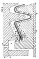
- Fig. 3 shows a sectional view along the line II-II of Fig. 1, wherein the filter material of the filter according to Fig. 1 is arranged between the two halves of an injection mold for molding synthetic material around the filter material and the two halves of the injection molded are not yet fully moved into their closed condition,
- Fig. 4 shows a sectional view similar to Fig. 3 in the closed condition of the injection mold.
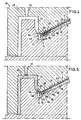
- Fig. 5 shows a view similar to Fig. 4 wherein, however, that partial space of the frame-forming molding space which follows the injection channel or the injections channels is already filled with injected synthetic material.
- Fig. 6 shows a sectional view similar to Fig. 5 wherein, however, the whole molding space is filled with synthetic material.
- Fig. 7 shows an enlarged view of the region VII of Fig. 2 for better illustration of the transition space between the frame and the therein embedded filter material of the filter according to Fig. 1.
- Figs. 1, 2 and 7 show full or partial views of a filter element 10 which, by means of an injection mold according to Figs. 3 to 6 has been provided with a frame structure of a synthetic material arranged therearound by insert molding.
- Filter element 10 comprises a three-layered filter material 12 arranged in zig-zag-shaped or wave-shaped folds.
- the edge 14 of f ilter material 12 is surrounded by a continuous frame 16 of a synthetic material having the edge 14 of the filter material embedded therein. In this manner, a tight mechanical connection is established between the frame 16 and the filter material 12, with the frame 16 supporting the zig-zag or wave structure of filter material 12.
- the filter material 12 comprises a filtering non-woven layer 18.
- This filtering non-woven layer 18 acts like a particle filter and comprises individual fibers of a synthetic material with electric properties.
- Arranged on the filtering non-woven layer 18 is an active carbon layer 20 of active carbon particles.
- This active carbon layer 20 functions like a deodorizing filter and will trap, e.g., harmful substances from the fluid - particularly air - which is to be filtered.
- a cover non-woven layer 22 of synthetic fibers is arranged on the side of the active carbon layer 20 facing away from the filtering non-woven layer 18.
- the thickness of the cover non-woven layer 22 is substantially smaller than the thickness of the filtering non-woven layer 18.
- cover nonwoven layer 22 has a considerably larger stiffness than the filtering non-woven layer 18.
- the direction of the fluid flow to be filtered by the filter 10 is indicated by an arrow at 24.
- the filtering non-woven layer 18 in the flow direction 24 is arranged before the active carbon layer 20 which in turn has the cover non-woven layer 22 arranged therebehind.
- the purpose of cover non-woven layer 22 resides primarily in preventing a detachment of particles of the active carbon layer 20 and lending support to the active carbon layer 20 as a whole.
- the three-layered filter material 12 is inserted into the injection mold 26, partially shown in Fig. 3 in sectional view, which comprises an upper mold half 28 and a lower mold half 30. Both mold halves 28,30 comprise mutually confronting mold walls 32,34 forming spaces therebetween which will be described in greater detail hereunder.
- the two mold halves 28,30 define a wave-like receiving space 36 therebetween for receiving the filter material 12.
- the receiving space 36 is followed by a transition space 38 having the edge portion 40 extending therethrough.
- the end of transition space 38 facing away from receiving space 36 is followed by a molding space 42 whose configuration will define the shape of frame 16.
- the edge 14 of filter material 12 projects from transition space 38 into molding space 42.
- a synthetic material e.g. polypropylene
- a synthetic material e.g. polypropylene
- the filter material 12 it is imperative that the injected synthetic material will not penetrate into all of the regions of the inserted part, i.e. the filter material 12.
- a tight closure must be obtained between the two mold halves 28,30 on the one hand and the filter material 12 on the other hand to thus provide a fluid-tight sealing for the injected synthetic material.
- a fluid-tight closure between the two mold halves 28,30 on the one hand and the filter material 12 on the other hand is realized by providing the transition space 38 with a constricted portion 46 within which the mold walls 32,34 are formed with projections 48,50.
- the projection 48 of the upper mold half 28 is of a substantially trapezoidal shape and has a continuous, flat outer face 52 directed towards the lower mold half 30
- the outer side 54 of the projection 50 of the lower mold half 30 is formed with three mutually parallel, longitudinal ribs 56 with deepened portions 58 arranged therebetween.
- the ribs 56 and the deepened portions 58 run along the direction of the edge portion 40 and the edge 14 of filter material 12, respectively.
- the edge portion 40 of filter material 12 is heavily compressed by the ribs 56 along three zones.
- the height of the ribs 56 is selected in accordance with the nature (compressibility and composition) of the synthetic material and the injection pressures of the synthetic material in such a manner that, in these zones, there will be generally a tight abutment of the two mold halves 28,30 on the filter material 12.
- the ribs 56 act on the filtering non-woven layer 18, while the projection 48 of the upper mold half 28 acts on the cover non-woven layer 22 of the filter material 12.
- the active carbon layer 20 arranged between the non-woven layers 18 and 22 is compressed.
- the deepened portions 58 arranged between the ribs 56 define widened portions 62 which can serve for accommodating filter material displaced in the narrowed portions 60.
- the molding space 42 is provided at 64 with a constriction (narrowed portion) provided as a reduction of cross-section and formed by mutually confronting projections 66,68 of the mold walls 32,34 of the two mold halves 28,30.
- the molding space 42 is divided into first and second partial spaces 70,72.
- the second partial space 72 forms the connecting space between the first partial space 70 of the molding space 42 and the transition space 38.
- This second partial space 72 which thus joins the transition space 38 while arranged opposite to the receiving space 36, has the edge 14 of the filter material projecting thereinto.
- the injection channels 44 enter into the first partial space 70 of molding space 42.
- the shape of the molding space 42 resembles a U of which one leg has its free end is formed by the second partial space 72.
- the three-layered filter material 12 is folded into a zig-zag-shape and placed into the lower mold half 30 of the injection mold 26. Subsequently, the upper mold half 28 is moved against the lower mold half 30, thus closing the injection mold 26 (cf. Fig. 4) In this condition, the filter material 12, except for its edge portion 40, is arranged in the receiving space 36 of injection mold 26. The edge portion 40 of the filter material 12 extends through the transition space 38 up to the molding space 42, with the actual edge 14 of the filter material 12 projecting into the second partial space 72 of molding space 42.
- the two mold halves 28,30 can be brought to a suitable temperature so that the injected synthetic material will not cool down too much during the actual injection process.
- the edge 14 of filter material 12; projecting into the second partial space 72 of molding space 42, is enclosed by synthetic material 74.
- synthetic material 74 In other words, this means that the filter material 12 along its edge 14 is embedded in synthetic material 74.
- the synthetic material 74 has solidified, the two mold halves 28,30 are moved apart, and the filter material 12 along with the synthetic material molded therearound, i.e. the filter element 10, is removed from the injection mold 26.
- the solidified synthetic material 74 will then form the edge 14 of the filter material.
- the filter material has its edge portion 40 formed with depressions shaped as deepened grooves 76, with raised portions shaped as ribs 78 arranged therebetween.
- This structure is generated by a corresponding shape of the mold wall 34 of the lower mold half 30 in the constricted portion 46.
- the edge 14 of the filter material 12 is embedded on the free end 80 of one leg of the substantially U-shaped frame 16. This free end 80 is connected to the remaining part 84 of the frame 16 through a constricted portion 80 of reduced diameter.
Landscapes
- Engineering & Computer Science (AREA)
- Manufacturing & Machinery (AREA)
- Mechanical Engineering (AREA)
- Moulds For Moulding Plastics Or The Like (AREA)
- Filtering Materials (AREA)
- Injection Moulding Of Plastics Or The Like (AREA)
- Water Treatment By Sorption (AREA)
Applications Claiming Priority (3)
| Application Number | Priority Date | Filing Date | Title |
|---|---|---|---|
| DE19745919 | 1997-10-17 | ||
| DE1997145919 DE19745919C1 (de) | 1997-10-17 | 1997-10-17 | Spritzgußform zum Umspritzen von Kunststoff um ein Filtermaterial, Filter zum Filtern von Fluiden und Verfahren zum Herstellen eines derartigen Filters |
| PCT/US1998/021140 WO1999020450A1 (en) | 1997-10-17 | 1998-10-07 | Injection mold for insert-molding a synthetic material around a filter material, filter for the filtration of fluids and method for producing such filter |
Publications (2)
| Publication Number | Publication Date |
|---|---|
| EP1027200A1 EP1027200A1 (en) | 2000-08-16 |
| EP1027200B1 true EP1027200B1 (en) | 2004-05-06 |
Family
ID=7845838
Family Applications (1)
| Application Number | Title | Priority Date | Filing Date |
|---|---|---|---|
| EP98953293A Expired - Lifetime EP1027200B1 (en) | 1997-10-17 | 1998-10-07 | Injection mold for insert-molding a synthetic material around a filter material, filter for the filtration of fluids and method for producing such filter |
Country Status (6)
| Country | Link |
|---|---|
| EP (1) | EP1027200B1 (enExample) |
| JP (1) | JP2001520130A (enExample) |
| CA (1) | CA2306387A1 (enExample) |
| DE (1) | DE19745919C1 (enExample) |
| ES (1) | ES2221217T3 (enExample) |
| WO (1) | WO1999020450A1 (enExample) |
Families Citing this family (10)
| Publication number | Priority date | Publication date | Assignee | Title |
|---|---|---|---|---|
| GB2348622A (en) * | 1999-03-16 | 2000-10-11 | Minerva Technologies | Moulded filter plates |
| DE19958344C2 (de) * | 1999-12-03 | 2001-12-20 | Freudenberg Carl Fa | Werkzeug zur Herstellung einer Filterkassette mit Faltenbalg und Kunststoffrahmen |
| IT1320350B1 (it) * | 2000-05-12 | 2003-11-26 | Crs Srl Ct Ricerche & Sperimen | Procedimento ed attrezzatura per lo stampaggio a termocompressione diarticoli di materiale termoplastico. |
| DE10062423C1 (de) * | 2000-12-14 | 2002-06-06 | Freudenberg Carl Kg | Spritzgießwerkzeug zur Herstellung von Kunststoffrahmen bei Filterkassetten |
| DE10124846C1 (de) * | 2001-05-22 | 2003-05-28 | Freudenberg Carl Kg | Filterkassette und Spritzgiesswerkzeug zur Herstellung eines Kunststoffrahmens an einer Filterkassette und Filterkassette |
| GB2411367B (en) * | 2004-02-17 | 2008-06-04 | Nationwide Filter Company | Filter unit |
| DE102011083657A1 (de) * | 2011-09-28 | 2013-03-28 | Mahle International Gmbh | Filterelement |
| JP5748105B2 (ja) * | 2011-11-02 | 2015-07-15 | トヨタ紡織株式会社 | 成形構造体の製造方法及び成形型 |
| DE102012220180A1 (de) * | 2012-11-06 | 2014-05-08 | Röchling Automotive AG & Co. KG | Flächiges Verbundbauteil sowie Verfahren und Vorrichtung zur Herstellung desselben |
| CA3013658C (en) * | 2016-02-09 | 2023-02-21 | Clarcor Air Filtration Products, Inc. | Panel filter with molded frame and integral seal |
Family Cites Families (9)
| Publication number | Priority date | Publication date | Assignee | Title |
|---|---|---|---|---|
| DE2162355C3 (de) * | 1971-12-16 | 1981-09-17 | Purolator Filter GmbH, 7110 Öhringen | Gießvorrichtung zum Herstellen eines Flachfiltereinsatzes für Gase |
| US4138460A (en) * | 1977-06-10 | 1979-02-06 | Cordis Dow Corp. | Method for forming tubesheets on hollow fiber tows and forming hollow fiber bundle assemblies containing same |
| AU540096B2 (en) * | 1982-08-04 | 1984-11-01 | Nippondenso Co. Ltd. | Filter device and manufacturing method |
| US4543283A (en) * | 1984-09-04 | 1985-09-24 | Libbey-Owens-Ford Company | Encapsulated glazing product |
| DE3440326C2 (de) * | 1984-11-05 | 1996-04-11 | Leifheit Ag | Verfahren zur Herstellung eines Haushaltssiebes |
| JPS63287521A (ja) * | 1987-05-19 | 1988-11-24 | Shuji Harada | エア−クリ−ナ−用ダストネツトとその製造方法 |
| JPS63306266A (ja) * | 1987-06-04 | 1988-12-14 | Nippon Denso Co Ltd | 濾過エレメントの製造方法 |
| EP0448876A3 (en) * | 1990-03-29 | 1992-12-02 | Minnesota Mining And Manufacturing Company | Filter cartridge |
| DE4415886A1 (de) * | 1994-05-05 | 1995-11-09 | Coronet Werke Gmbh | Verfahren zur Herstellung von Borstenwaren im Wege des Spritzgießens |
-
1997
- 1997-10-17 DE DE1997145919 patent/DE19745919C1/de not_active Expired - Lifetime
-
1998
- 1998-10-07 JP JP2000516820A patent/JP2001520130A/ja not_active Ceased
- 1998-10-07 CA CA002306387A patent/CA2306387A1/en not_active Abandoned
- 1998-10-07 EP EP98953293A patent/EP1027200B1/en not_active Expired - Lifetime
- 1998-10-07 WO PCT/US1998/021140 patent/WO1999020450A1/en not_active Ceased
- 1998-10-07 ES ES98953293T patent/ES2221217T3/es not_active Expired - Lifetime
Also Published As
| Publication number | Publication date |
|---|---|
| DE19745919C1 (de) | 1999-08-12 |
| WO1999020450A1 (en) | 1999-04-29 |
| JP2001520130A (ja) | 2001-10-30 |
| CA2306387A1 (en) | 1999-04-29 |
| EP1027200A1 (en) | 2000-08-16 |
| ES2221217T3 (es) | 2004-12-16 |
Similar Documents
| Publication | Publication Date | Title |
|---|---|---|
| US6375699B1 (en) | Injection mold for insert-molding a synthetic material around a filter material, filter for the filtration of fluids and method for producing such filter | |
| EP1027200B1 (en) | Injection mold for insert-molding a synthetic material around a filter material, filter for the filtration of fluids and method for producing such filter | |
| KR101853507B1 (ko) | 필터 부재 및 필터 부재를 제조하기 위한 방법 | |
| US5958097A (en) | Filter insert | |
| US6485538B1 (en) | Air-conditioning air filter | |
| US5679122A (en) | Filter for the filtration of a fluid flow | |
| CN1259118C (zh) | 空气过滤构件及其制造方法 | |
| US6926828B2 (en) | Fluid filter | |
| US6165403A (en) | Method for the manufacture of a filter cartridge | |
| KR100211352B1 (ko) | 할로우 팬 날개를 성형하기 위한 방법 및 장치 | |
| CA2279201A1 (en) | Sealing means for electrically driven water purification units and method of manufacturing thereof | |
| DE10058478A1 (de) | Flaches Filterelement mit angegossenem Rahmen | |
| CA2036639A1 (en) | Filter cartridge | |
| CA2061454C (en) | Filter element and method for producing the same | |
| US10213534B2 (en) | Blood processing filter and blood processing filter manufacturing method | |
| US7735659B2 (en) | Filter element mounting apparatus | |
| JPS6041517A (ja) | エアクリ−ナエレメントの製造方法 | |
| CN105246571A (zh) | 具有双褶皱包的过滤器 | |
| KR100402719B1 (ko) | 필터 카트리지 제조 방법 및 그 방법을 실시하기 위한공구 | |
| JP2794512B2 (ja) | 立体型フィルタの製造方法 | |
| AU739688B2 (en) | Moulded filter media comprising a sheet of porous nonwoven material | |
| KR100518036B1 (ko) | 자동차용 에어필터 제조장치 | |
| JP3775267B2 (ja) | エアクリーナエレメント用ひだ密着防止部材及びエアクリーナエレメント | |
| JP2009262115A (ja) | エアフィルタユニット | |
| CN101346170A (zh) | 过滤器元件 |
Legal Events
| Date | Code | Title | Description |
|---|---|---|---|
| PUAI | Public reference made under article 153(3) epc to a published international application that has entered the european phase |
Free format text: ORIGINAL CODE: 0009012 |
|
| 17P | Request for examination filed |
Effective date: 20000405 |
|
| AK | Designated contracting states |
Kind code of ref document: A1 Designated state(s): ES FR GB IT SE |
|
| 17Q | First examination report despatched |
Effective date: 20010625 |
|
| GRAP | Despatch of communication of intention to grant a patent |
Free format text: ORIGINAL CODE: EPIDOSNIGR1 |
|
| GRAS | Grant fee paid |
Free format text: ORIGINAL CODE: EPIDOSNIGR3 |
|
| GRAA | (expected) grant |
Free format text: ORIGINAL CODE: 0009210 |
|
| AK | Designated contracting states |
Kind code of ref document: B1 Designated state(s): ES FR GB IT SE |
|
| REG | Reference to a national code |
Ref country code: GB Ref legal event code: FG4D |
|
| REG | Reference to a national code |
Ref country code: SE Ref legal event code: TRGR |
|
| REG | Reference to a national code |
Ref country code: ES Ref legal event code: FG2A Ref document number: 2221217 Country of ref document: ES Kind code of ref document: T3 |
|
| ET | Fr: translation filed | ||
| PLBE | No opposition filed within time limit |
Free format text: ORIGINAL CODE: 0009261 |
|
| STAA | Information on the status of an ep patent application or granted ep patent |
Free format text: STATUS: NO OPPOSITION FILED WITHIN TIME LIMIT |
|
| 26N | No opposition filed |
Effective date: 20050208 |
|
| PGFP | Annual fee paid to national office [announced via postgrant information from national office to epo] |
Ref country code: ES Payment date: 20071026 Year of fee payment: 10 |
|
| PGFP | Annual fee paid to national office [announced via postgrant information from national office to epo] |
Ref country code: IT Payment date: 20071029 Year of fee payment: 10 |
|
| PGFP | Annual fee paid to national office [announced via postgrant information from national office to epo] |
Ref country code: SE Payment date: 20071029 Year of fee payment: 10 |
|
| PGFP | Annual fee paid to national office [announced via postgrant information from national office to epo] |
Ref country code: GB Payment date: 20071029 Year of fee payment: 10 |
|
| EUG | Se: european patent has lapsed | ||
| GBPC | Gb: european patent ceased through non-payment of renewal fee |
Effective date: 20081007 |
|
| PG25 | Lapsed in a contracting state [announced via postgrant information from national office to epo] |
Ref country code: IT Free format text: LAPSE BECAUSE OF NON-PAYMENT OF DUE FEES Effective date: 20081007 |
|
| PG25 | Lapsed in a contracting state [announced via postgrant information from national office to epo] |
Ref country code: GB Free format text: LAPSE BECAUSE OF NON-PAYMENT OF DUE FEES Effective date: 20081007 |
|
| REG | Reference to a national code |
Ref country code: ES Ref legal event code: FD2A Effective date: 20081008 |
|
| PG25 | Lapsed in a contracting state [announced via postgrant information from national office to epo] |
Ref country code: ES Free format text: LAPSE BECAUSE OF NON-PAYMENT OF DUE FEES Effective date: 20081008 |
|
| PG25 | Lapsed in a contracting state [announced via postgrant information from national office to epo] |
Ref country code: SE Free format text: LAPSE BECAUSE OF NON-PAYMENT OF DUE FEES Effective date: 20081008 |
|
| REG | Reference to a national code |
Ref country code: FR Ref legal event code: PLFP Year of fee payment: 18 |
|
| REG | Reference to a national code |
Ref country code: FR Ref legal event code: PLFP Year of fee payment: 19 |
|
| REG | Reference to a national code |
Ref country code: FR Ref legal event code: PLFP Year of fee payment: 20 |
|
| PGFP | Annual fee paid to national office [announced via postgrant information from national office to epo] |
Ref country code: FR Payment date: 20170918 Year of fee payment: 20 |