EP1026618B1 - Transponder-Leseeinrichtung - Google Patents
Transponder-Leseeinrichtung Download PDFInfo
- Publication number
- EP1026618B1 EP1026618B1 EP00102402A EP00102402A EP1026618B1 EP 1026618 B1 EP1026618 B1 EP 1026618B1 EP 00102402 A EP00102402 A EP 00102402A EP 00102402 A EP00102402 A EP 00102402A EP 1026618 B1 EP1026618 B1 EP 1026618B1
- Authority
- EP
- European Patent Office
- Prior art keywords
- antenna arrangement
- transponder
- partial loop
- partial
- antenna
- Prior art date
- Legal status (The legal status is an assumption and is not a legal conclusion. Google has not performed a legal analysis and makes no representation as to the accuracy of the status listed.)
- Expired - Lifetime
Links
Images



Classifications
-
- G—PHYSICS
- G06—COMPUTING OR CALCULATING; COUNTING
- G06K—GRAPHICAL DATA READING; PRESENTATION OF DATA; RECORD CARRIERS; HANDLING RECORD CARRIERS
- G06K7/00—Methods or arrangements for sensing record carriers, e.g. for reading patterns
- G06K7/10—Methods or arrangements for sensing record carriers, e.g. for reading patterns by electromagnetic radiation, e.g. optical sensing; by corpuscular radiation
- G06K7/10009—Methods or arrangements for sensing record carriers, e.g. for reading patterns by electromagnetic radiation, e.g. optical sensing; by corpuscular radiation sensing by radiation using wavelengths larger than 0.1 mm, e.g. radio-waves or microwaves
- G06K7/10316—Methods or arrangements for sensing record carriers, e.g. for reading patterns by electromagnetic radiation, e.g. optical sensing; by corpuscular radiation sensing by radiation using wavelengths larger than 0.1 mm, e.g. radio-waves or microwaves using at least one antenna particularly designed for interrogating the wireless record carriers
- G06K7/10346—Methods or arrangements for sensing record carriers, e.g. for reading patterns by electromagnetic radiation, e.g. optical sensing; by corpuscular radiation sensing by radiation using wavelengths larger than 0.1 mm, e.g. radio-waves or microwaves using at least one antenna particularly designed for interrogating the wireless record carriers the antenna being of the far field type, e.g. HF types or dipoles
-
- G—PHYSICS
- G06—COMPUTING OR CALCULATING; COUNTING
- G06K—GRAPHICAL DATA READING; PRESENTATION OF DATA; RECORD CARRIERS; HANDLING RECORD CARRIERS
- G06K7/00—Methods or arrangements for sensing record carriers, e.g. for reading patterns
- G06K7/10—Methods or arrangements for sensing record carriers, e.g. for reading patterns by electromagnetic radiation, e.g. optical sensing; by corpuscular radiation
- G06K7/10009—Methods or arrangements for sensing record carriers, e.g. for reading patterns by electromagnetic radiation, e.g. optical sensing; by corpuscular radiation sensing by radiation using wavelengths larger than 0.1 mm, e.g. radio-waves or microwaves
- G06K7/10316—Methods or arrangements for sensing record carriers, e.g. for reading patterns by electromagnetic radiation, e.g. optical sensing; by corpuscular radiation sensing by radiation using wavelengths larger than 0.1 mm, e.g. radio-waves or microwaves using at least one antenna particularly designed for interrogating the wireless record carriers
- G06K7/10336—Methods or arrangements for sensing record carriers, e.g. for reading patterns by electromagnetic radiation, e.g. optical sensing; by corpuscular radiation sensing by radiation using wavelengths larger than 0.1 mm, e.g. radio-waves or microwaves using at least one antenna particularly designed for interrogating the wireless record carriers the antenna being of the near field type, inductive coil
-
- G—PHYSICS
- G06—COMPUTING OR CALCULATING; COUNTING
- G06K—GRAPHICAL DATA READING; PRESENTATION OF DATA; RECORD CARRIERS; HANDLING RECORD CARRIERS
- G06K7/00—Methods or arrangements for sensing record carriers, e.g. for reading patterns
- G06K7/10—Methods or arrangements for sensing record carriers, e.g. for reading patterns by electromagnetic radiation, e.g. optical sensing; by corpuscular radiation
- G06K7/10009—Methods or arrangements for sensing record carriers, e.g. for reading patterns by electromagnetic radiation, e.g. optical sensing; by corpuscular radiation sensing by radiation using wavelengths larger than 0.1 mm, e.g. radio-waves or microwaves
- G06K7/10366—Methods or arrangements for sensing record carriers, e.g. for reading patterns by electromagnetic radiation, e.g. optical sensing; by corpuscular radiation sensing by radiation using wavelengths larger than 0.1 mm, e.g. radio-waves or microwaves the interrogation device being adapted for miscellaneous applications
- G06K7/10415—Methods or arrangements for sensing record carriers, e.g. for reading patterns by electromagnetic radiation, e.g. optical sensing; by corpuscular radiation sensing by radiation using wavelengths larger than 0.1 mm, e.g. radio-waves or microwaves the interrogation device being adapted for miscellaneous applications the interrogation device being fixed in its position, such as an access control device for reading wireless access cards, or a wireless ATM
- G06K7/10425—Methods or arrangements for sensing record carriers, e.g. for reading patterns by electromagnetic radiation, e.g. optical sensing; by corpuscular radiation sensing by radiation using wavelengths larger than 0.1 mm, e.g. radio-waves or microwaves the interrogation device being adapted for miscellaneous applications the interrogation device being fixed in its position, such as an access control device for reading wireless access cards, or a wireless ATM the interrogation device being arranged for interrogation of record carriers passing by the interrogation device
- G06K7/10435—Methods or arrangements for sensing record carriers, e.g. for reading patterns by electromagnetic radiation, e.g. optical sensing; by corpuscular radiation sensing by radiation using wavelengths larger than 0.1 mm, e.g. radio-waves or microwaves the interrogation device being adapted for miscellaneous applications the interrogation device being fixed in its position, such as an access control device for reading wireless access cards, or a wireless ATM the interrogation device being arranged for interrogation of record carriers passing by the interrogation device the interrogation device being positioned close to a conveyor belt or the like on which moving record carriers are passing
Definitions
- the present invention relates to a transponder reading device, a secure identification of a Transponders enabled.
- Transponders are transceivers, usually to manage without their own energy supply. Be transponder addressed by an electromagnetic high frequency field and derive their operating power by rectifying the RF field. They are usually configured to in response to a particular receive signal a particular one Function to perform. This feature can, for example in that they in turn have an associated one Send Identification ID that they have assigned to them Describe memory or that it is any other Send a signal, which in turn received by a receiver can and become aware of a particular one Property of the transponder.
- transponders common in the market, for example, in labels can be incorporated to identify an item, on which the label is arranged or glued is.
- the label for example, to think of the postal distribution. On packets is indeed a human-readable address glued on, but the actual distribution can be by means of a transponder housed in this label be performed by a suitable reader can be addressed.
- Such a label with a electronic transponder is then lapsed, if that Package has been shipped and the label to some extent is broken.
- Such transponders must be very reasonably priced because they are disposable.
- an on Initialized a transponder applied to a package for example, by a serial number on to point out a special package.
- the Transponder to a certain question data sequence the destination address of the package.
- Such a package when it is delivered to a post office several Distribution points run to the addressee.
- An example for describing the transponder could be about the Etiquette assigned to the package transponder at each distribution point be described with a specific code to to follow the path of the package.
- An example of writing of a transponder is of course the Initial initialization, d. H. the original input of the Destination address.
- a reading device can activate the transponders of the individual packages, to determine their destination address, the same of the Main conveyor belt suitable to distribute.
- Such transponders are mainly used as identification systems used. Everywhere, where certain items automatically can be identified, such inexpensive Identification transponder, z. B. in labels used, are used.
- An antenna arrangement on the one hand has a sufficiently large field density generate, so that the transponder enough electrical energy can "pull" out of the antenna field. Beyond that exist certain frequency bands released for such radio systems are. Finally, there is an essential constraint for such antenna arrangements in that the dimensions z. B. the conveyor belt or the objects with Transponders are equipped, are fixed and no Possibility exists, the objects or conveyors Antenna geometries adapt, but that rather the antenna geometries to existing conveyor belts and existing ones Object sizes must be adjusted. To the example of the It must be possible to keep packages, even packages to handle with a height of up to 90 cm. The Packet size can not be changed due to antenna geometry but the antenna geometry has been adapted to the Package size and also to existing conveyor belt facilities necessarily adapt. In addition, the labels can be general be anywhere on the package.
- Fig. 7 shows a known embodiment of an antenna arrangement including wiring to transponders attached to objects read on a conveyor belt or with the same to communicate.
- the arrangement comprises a transponder reader 100, which provides electrical signals to the Transponders should be sent, or the electrical Receive signals from the transponders.
- the two frame antennas 106 and 110 are left and right, respectively, in the known arrangement with respect to a conveying direction 112, the dashed in Fig. 7 as Arrow symbolizes, arranged. With it too high or large packets in connection with that shown in Fig. 7 Arrangement can be used, the two must received considerable dimensions separate frame antennas.
- the field strength must be at a permissible maximum limited by the national authorities of the country is, in which the plant is operated.
- the two matching networks 104 and 108 must be closely aligned so that the transponder signals can be received correctly and from the transponder reader 100 evaluated as error-free can be.
- the antenna In order to become independent of the stray capacities, the antenna must be connected with a capacity which is significantly higher than the stray capacitances, such that variable stray capacitances only negligible Affect the antenna operation. If, however, the Inductance of the antenna is already very large, it would no longer be possible to have a particularly large capacity too the antenna to switch to a specific operating frequency in the range between 10 and 20 MHz. Therefore exists the requirement, the inductance of the antenna as possible keep small, so as large as possible defined capacity to be interconnected with the antenna can.
- a transponder reading device comprising a guide device, wherein an antenna through two serially interconnected coils is formed, on both sides of the guide device extends. Furthermore, a shield is provided which Having slots through which the functionality of a magnetic antenna is achieved.
- an identification system comprising a transmitter unit and a sensor unit.
- Two Antenna loops are arranged so that they the Direction of objects that can pass, capture and furthermore dead zones, in which a detection is not possible, be avoided.
- Objects to capture include labels, have the resonant circuits that are different Frequencies are tuned.
- the one for the capture essential aspect is that the labels be moved through the closed antenna loops.
- the object of the present invention is to provide a Transponder reading device to create a reliable Communication with transponders allows.
- the present invention is based on the knowledge that the use of two loop antennas, to minimize their inductance, have only one turn, but together with appropriate for transponder systems necessary control yet represent two turns, must be spaced to to get a sufficiently large antenna that with the required Operating frequencies safely operated despite their size can be.
- a single closed antenna winding used and in Form of a "folded eight" arranged such that a first sub-loop (the upper "circle” of the number 8) and one second partial loop (the lower “circle” of the number 8) arises, but not arranged in a single plane but in respective levels, which are in a bit sharp Cut angles or are parallel.
- the feeding of the Antenna arrangement for the transponder reading device according to the invention finds in the middle, so the "knot” of "Eight” instead, so that a parallel connection of the two Partial grinding results, but together only one result in a single turn.
- the feeding of the two partial loops is thus automatically identical, such that only one Matching network is needed because the two sub-loops automatically matched.
- the only one Winding comprises, formed from the two sub-loops can, the inductance of the entire antenna array be kept as small as possible. Thus, they are essential larger loop cross sections feasible.
- Invention will be the only turn in addition between the crossed over the upper sub-loop and the lower sub-loop, such that the current flow directions in the two sub-loops, arranged in two superposed planes are opposite, what are opposing Orientation of the generated by the two sub-loops Fields introduces itself around the antennas possible inhomogeneous magnetic field, such that transponder identified in substantially any orientation can be.
- the extent of a partial loop without such a strong one Impact on the inductance made much larger not only is it possible to place objects between them to move through both partial loops, but also through to move the partial loops through themselves. With that brought the transponder in the vicinity of the antenna.
- a preferred embodiment The present invention thus supports Systems with shorter ranges, d. H. lower Transmit power of both the antenna, and, perhaps, what even more crucial is the transponder itself, yes has no own energy supply, but the transmission energy must refer from the RF field of the antenna assembly.
- Another particular advantage of the present invention is that solely by the geometric arrangement the two sub-loops to each other or to the reading area Field zeros can be manipulated so that it is in Reading area essentially no "dead" areas, d. H. Areas where there are no magnetic fields, being particularly It should be noted that this is true for all transponder orientations with respect to the antennas or the reading area applies.
- Fig. 1 shows a schematic perspective view an antenna arrangement according to the invention according to a preferred Embodiment of the present invention.
- the antenna arrangement has a first partial loop 12, a second sub-loop 14 and a single feed device 16 on.
- the reference coordinate system is indicated.
- the first sub-loop 12 is arranged in the xz-plane is at a first y-coordinate.
- the second sub-loop 14 is also in an xz plane, but at a different y coordinate than the first level, d. H. the first sub-loop 12. From Fig. 1 It can also be seen that the two levels in which the Both partial loops are substantially parallel to each other.
- the two partial loops could be tilted with respect to the yz plane such that The two levels, passing through the two partial loops 12 and 14 are defined, intersect at an acute angle.
- An arrangement in which the two partial loops 12, 14 in same level, d. H. an unfolded eight, does not bring the benefit of the invention, since the two sub-loops that are not arranged opposite each other are defined, no volume thought by that too identifying transponder can be moved through or introduced into the transponder to be identified can be. With an antenna in the form of an unfolded, standing eight this is not the case.
- the two sub-loops not just flat rectangles or even circular ones Must be frame, but also arbitrarily shaped convex and / or concave surfaces.
- the first Partial loop and the second part loop only need be positioned to each other so that flat surfaces, the at any convex or concave through the first and the second sub-loop defined areas are approximated, are parallel to each other or at an acute angle to cut. Only with this is between the two arbitrary formed partial loops 12, 14, which arbitrarily each other are arranged opposite each other, defining a volume of thought, moved through the transponder to be identified can be, or in the transponder to be identified can be introduced.
- Fig. 1 it can also be seen that the two sub-loops 12, 14 by crossing the conductors near the feed point be fed so that an opposing Stromflußcardi in the two sub-loops 12, 14 results.
- This is a special way in a beneficial manner Inhomogeneity between the two sub-loops 12, 14, so in the imaginary volume, generated.
- the crossover does not exist, such that a same direction current flow direction between the two a single point powered sub-loops 12, 14 available is.
- the advantage of the invention is achieved in that the surface formed by the partial loops 12, 14 is enclosed, can be increased without the inductance the antenna arrangement increases as much as if one analog antenna arrangement, which is a single loop antenna has, is dimensioned accordingly to the same Enclose surface.
- the inductance of Antenna arrangement are kept within limits, what to do leads that relatively large circuit capacities used be possible to get one of stray capacities as possible independent antenna operation to be able to receive.
- Fig. 2a shows a folded-up representation of the antenna arrangement of Fig. 1. Further, the current flow directions, d. H. the arrows marked I, in the two partial loops 12, 14 drawn. As in Fig. 1 is in Fig. 2a shown the situation where the two opposite Partial loops have opposite directions of current flow, what by crossing the conductor areas 18a and 18b in the feed area reached between the two sub-loops becomes. Alternatively, however, could be dispensed with a crossover become what figuratively speaking simply by it is achieved, for example, if the upper part loop 14th rotated about the z-axis by 180 degrees. Will against it the crossover is omitted, the result is an equal sense Current flow direction in the two sub-loops
- Fig. 2b shows schematically possible side views for a Antenna arrangement according to the invention. As shown to the right of FIG. 2b, this is a top view of the yz plane. At the far left of Fig. 2b is a general antenna arrangement with the first and second partial loops 12, 14 and a feeding device 16, in which the conductors 18a, 18b (Fig. 2a) are not present. Fig. 2b shows the Side elevational view of the antenna arrangement shown in Fig. 1. The third top view from the left shows one opposite modified the antenna arrangement shown in Fig. 1 Arrangement in which the two surfaces passing through the Partial loops 12, 14 are defined, parallel to each other are not, however, to the conductor pieces 18a, 18b (Fig. 2b) are arranged vertically.
- the second part from the right in Fig. 2b shows yet another configuration in which the two surfaces defined by the partial loops are, fictively intersect at an acute angle and further have an acute angle to the conductor pieces 18a, 18b.
- the illustration on the far right in Fig. 2b should symbolize that the two partial loops 12, 14 are not necessarily flat Must include surfaces, but that the areas through the partial loops 12, 14 are enclosed, arbitrarily convex and / or may be concave, with the surfaces, the be enclosed by the two sub-loops 12, 14, also different from each other.
- two to the surfaces passing through the partial loops are enclosed, approximate flat surfaces, the in dashed lines in the rightmost field of Fig. 2b are, have to be in parallel or in one must cut acute angle to the inventive Advantage of limited inductance increase with increasing To achieve dimensions.
- Figs. 1 and 2a it is preferable is to feed the antenna arrangement symmetrically. This is preferably done by means of a balun, the one unbalanced RF input, which normally has an impedance of 50 n, and that has two balanced outputs (+ V and -V) connected to the feeding device of the antenna arrangement, d. H. with the supply terminals preferably in the middle of the single turn from which the inventive antenna assembly is formed connected are.
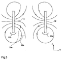
- Fig. 3 shows a plan view of the antenna arrangement according to the invention in their preferred shown in Fig. 1 Design with parallel partial loops 12, 14, which are also fed in opposite directions, what by the Crossover of the conductor pieces 18a, 18b (Fig. 2a) reached becomes.
- Fig. 3 further shows a first transponder 20a and a second transponder 20b parallel to the z-direction moved between the two sub-loops 12, 14 therethrough become.
- the two transponders 20a and 20b have one different orientation, d. H. the first transponder 20a is aligned parallel to the z-direction, while the second transponder 20b aligned parallel to the y-direction is.
- Fig. 3 shows a situation in which the transponder moved between the two sub-loops 12, 14 therethrough be
- the transponder 20a, 20b not to pass between the partial loops 12, 14, but by the sub-loops 12, 14 itself "dive through” to let, d. H. to move in the y-direction.
- the representation of Fig. 3 with respect to the identifiability of the transponder 20a, 20b, the different orientations with respect of the antenna arrangement is analogous to itself in the y-direction moving transponders that pass through the surfaces, which are enclosed by the partial loops 12, 14, applicable, since the field representation shown in FIG the z-axis and the y-axis double axisymmetric is.
- transponders should also be used in the Middle between the two sub-loops 12, 14 read, so the field can be varied by the individual sub loops for example, around the upper endpoint of the same to some extent be rotated as indicated by the two arrows 22a and 22b is shown.
- plan views as shown in Fig. 2b are generated.
- the zero point in the middle of the Reading area are moved out of the same or to a Edge of the same are brought, where they no longer matter plays.
- the antenna arrangement comprises the first sub-loop 12, the second sub-loop 14, in which shown in Fig. 4 preferred embodiment, first and second conductor pieces 18a, 18b, shown schematically as a dashed line are shown, the antenna sub-loops 12, 14th connects, as well as the only supply device 16.
- the transport device designed as an endless device, usually a drive roller 43, a follower roller 44 and a Conveyor belt 45 has.
- Figs. 5 and 6 show alternative Positioning of the antenna arrangement, or the partial loops 12, 14 with respect to the reading area 40, for example the zero point used in connection with FIG. 3 has been described to another part of the reading area, where it does not bother or from the reading area 40 to bring out.
- the partial loops not just rotate around the x-axis, but that they are rotated about all three axes can be used to bring field zeros out of the reading range or to change the field direction as needed to a to achieve secure transponder identification.
- the antenna form according to the invention leads in its all possible configurations, of which only a few are shown in Fig. 2b, to a reduction of the coil inductance.
- the coil inductance is mainly is determined by the clamped frame surface
- the resonant capacity is made up of the designated one concentrated circuit capacity and stray capacitance the environment together.
- the circuit capacity for a same resonant frequency, d. H. an operating frequency for the antenna arrangement which is between 12 and 14 MHz and preferably 13.56 MHz is chosen as large as possible become.
- the "parallel connection" (center point supply) of Both partial loops contribute to the smallest inductance a predetermined antenna size.
- connection of the two conductor strips leads to a formation of the magnetic Feldes, between the two conductor loops is directed in the same direction or in opposite directions. This will ensure that a transponder in all orientation directions is read.
- the preferred "dipping" of the transponder by the loops in a preferred embodiment of The invention are the same in the vicinity of the Antenna, d. H.
- the reading distances are lower than at one comparable gate antenna with two lateral loop antennas, as shown with respect to FIG. 7.
- the Preferably provided inclination of the two sub-loops can in a plane arbitrarily aligned transponder be read reliably. If in addition the opposing Field orientation is chosen, as is the case with the antenna arrangement 1, the third orientation direction may also be used of transponders, so an alignment perpendicular to the transport direction, reliably processed become.
- Another important advantage of the antenna arrangement according to the invention is that the geometry of the same to existing dimensions of objects to be identified, such as z. As standardized postal packages, can be adjusted.
- the distance the two sub-loops 12, 14 in the in Fig. 1st illustrated preferred embodiment is of the movement speed and the length of the transponder communication protocol dependent and can be within limits be set.
Landscapes
- Engineering & Computer Science (AREA)
- Physics & Mathematics (AREA)
- Health & Medical Sciences (AREA)
- Toxicology (AREA)
- General Health & Medical Sciences (AREA)
- Electromagnetism (AREA)
- Computer Networks & Wireless Communication (AREA)
- Artificial Intelligence (AREA)
- Computer Vision & Pattern Recognition (AREA)
- General Physics & Mathematics (AREA)
- Theoretical Computer Science (AREA)
- Radar Systems Or Details Thereof (AREA)
- Near-Field Transmission Systems (AREA)
- Variable-Direction Aerials And Aerial Arrays (AREA)
- Control Of Conveyors (AREA)
Description
- u
- Umfang der Antennenschleife [cm]
- D
- Leiterzugbreite oder Durchmesser [cm]
- Kq
- Korrekturfaktor, der die Antennenform berücksichtigt (für quadratische Antennen beträgt Kq 1,47, für kreisförmige Antennen beträgt Kq 1,07)
- N
- Windungszahl
- L
- Antenneninduktivität [nH]
- Fig. 1
- eine Antennenanordnung für eine Transponder-Leseeinrichtung gemäß einem bevorzugten Ausführungsbeispiel der vorliegenden Erfindung;
- Fig. 2a
- eine "aufgefaltete" Darstellung der Antennenanordnung von Fig. 1;
- Fig. 2b
- schematische Seitenansichten verschiedener Antennenanordnungen für eine erfindungsgemäße Transponder-Leseeinrichtung;
- Fig. 3
- ein schematisches Diagramm der Feldverteilung der in Fig. 1 dargestellten Antennenanordnung, um die Identifikation unterschiedlich ausgerichteter Transponder zu veranschaulichen;
- Fig. 4
- eine erfindungsgemäße Transponder-Leseeinrichtung mit einer erfindungsgemäßen Antennenanordnung in einer bestimmten Ausrichtung bezüglich des Lesebereichs;
- Fig. 5
- eine erfindungsgemäße Transponder-Leseeinrichtung mit einer anderen Ausrichtung der Antennenanordnung bezüglich des Lesebereichs;
- Fig. 6
- eine erfindungsgemäße Transponder-Leseeinrichtung mit einer alternativen Ausrichtung der Antennenanordnung bezüglich des Lesebereichs; und
- Fig. 7
- eine Ausgestaltung einer bekannten Transponder-Leseeinrichtung mit zwei voneinander getrennten Rahmenantennen und zwei Anpaßnetzwerken.
Claims (14)
- Transponder-Leseeinrichtung mit folgenden Merkmalen:wobei die Antennenanordnung ausgebildet ist, um in dem Lesebereich (40) ein inhomogenes Magnetfeld zu erzeugen, indemeiner Antennenanordnung, die folgende Merkmale aufweist:eine erste Teilschleife (12), die eine erste Fläche im wesentlichen umschließt und ein erstes und ein zweites Ende hat;eine zweite Teilschleife (14), die eine zweite Fläche im wesentlichen umschließt und ein erstes und ein zweites Ende hat,wobei die beiden ersten Enden der ersten und der zweiten Teilschleife (12, 14) miteinander verbunden sind, und wobei die zweiten Enden der ersten und der zweiten Teilschleife miteinander verbunden sind, derart, daß die beiden Teilschleifen zusammen eine einzige geschlossene Windung bilden; undeine einzige Speisungseinrichtung (16) zum Anlegen einer Spannung (+V, -V) zwischen den verbundenen ersten Enden und den verbundenen zweiten Enden,wobei die erste und die zweiten Teilschleife (12, 14) derart zueinander positioniert sind, daß eine durch die erste Fläche definierte erste Ebene und eine durch die zweite Fläche definierte von der ersten Ebene unterschiedliche zweite Ebene sich parallel oder in einem spitzen Winkel schneidend gegenüberliegen;einem Lesebereich (40), der in einem Nahbereich der ersten und der zweiten Teilschleife gebildet ist;einer Einrichtung (42) zum Transportieren eines Objektes (44), an dem ein Transponder (20) angebracht ist, durch den Lesebereich (40),a) die erste und die zweite Teilschleife der Antennenanordnung derart miteinander verbunden sind, daß die Stromflußrichtung in der ersten Teilschleife entgegengesetzt zu der Stromflußrichtung in der zweiten Teilschleife gerichtet ist, oderb) die erste und die zweite Teilschleife der Antennenanordnung derart miteinander verbunden positioniert sind, daß die Stromflußrichtung in der ersten Teilschleife gleichsinnig zu der Stromflußrichtung in der zweiten Teilschleife gerichtet ist, und die Antennenanordnung schräg bezüglich der Einrichtung (42) zum Transportieren eines Objekts angeordnet ist.
- Transponder-Leseeinrichtung nach Anspruch 1, bei der der Lesebereich (40) einen länglichen Raum aufweist, der sich entlang einer Lesebereichsachse erstreckt, wobei die erste und die zweite Teilschleife (12, 14) jeweils den länglichen Raum im wesentlichen umgeben und bezüglich der Lesebereichsachse voneinander beabstandet sind, derart, daß das Objekt (44), an dem der Transponder (20) angebracht ist, durch die erste und die zweite Teilschleife (12, 14) gebracht werden kann.
- Transponder-Leseeinrichtung nach Anspruch 1,
bei der die Antennenanordnung so in dem Lesebereich (40) angeordnet ist, daß die erste und die zweite Teilschleife (12, 14) links bzw. rechts bezüglich des Lesebereichs (40) angeordnet sind, derart, daß ein Objekt zwischen die Teilschleifen (12, 14) transportiert werden kann, das Objekt (44) jedoch nicht durch eine der Teilschleifen (12, 14) hindurch transportiert werden kann. - Transponder-Leseeinrichtung nach einem der Ansprüche 1 bis 3, bei der die Transporteinrichtung (42) ferner angeordnet ist, um das Objekt (44) durch den Lesebereich (40) kontinuierlich hindurchzubewegen.
- Transponder-Leseeinrichtung nach einem der Ansprüche 1 bis 4, bei der die erste und die zweite Fläche parallel zueinander sind, einen länglichen Lesebereich jedoch in einem spitzen Winkel schneiden.
- Transponder-Leseeinrichtung nach einem der Ansprüche 1 bis 4, bei der die erste und die zweite Fläche einen spitzen Winkel definieren und einen länglichen Lesebereich in unterschiedlichen Winkeln schneiden.
- Transponder-Leseeinrichtung nach einem der Ansprüche 1 bis 6, bei der die Transporteinrichtung (42) als flaches Förderband (42) ausgestattet ist, das metallische Bestandteile aufweist.
- Transponder-Leseeinrichtung nach einem der Ansprüche 1 bis 7, bei der die Antennenanordnung bezüglich der Transporteinrichtung (42) derart angeordnet ist, daß die ersten und die zweiten Enden, die mit der Speisungseinrichtung (16) verbunden sind, möglichst weit von der Transporteinrichtung (42) entfernt angeordnet sind, um Ableitströme über Streukapazitäten zu minimieren.
- Transponder-Leseeinrichtung nach einem der Ansprüche 1 bis 8, bei der die erste Fläche und die zweite Fläche der Antennenanordnung ebene Flächen sind, die in der ersten und zweiten Ebene liegen.
- Transponder-Leseeinrichtung nach Anspruch 1,
bei der die erste und die zweite Fläche der Antennenanordnung im wesentlichen parallel zueinander sind,
bei der die erste Teilschleife (12) und die zweite Teilschleife (14) der Antennenanordnung als nahezu vollständige Rahmen ausgebildet sind, die lediglich durch einen bestimmten Abstand zwischen den ersten und den zweiten Enden geöffnet sind,
bei der die ersten und die zweiten Enden der ersten und der zweiten Teilschleife jeweils durch einen ersten (18a) bzw. einen zweiten (18b) Leiter miteinander verbunden sind,
wobei der erste und der zweite Leiter (18a, 18b) der Antennenanordnung im wesentlichen senkrecht zu der ersten und der zweiten Fläche verlaufen und ferner gekreuzt sind, so daß sich die gegensinnigen Stromflußrichtungen in den beiden Teilschleifen ergeben. - Transponder-Leseeinrichtung nach einem der vorhergehenden Ansprüche, bei der die erste und die zweite Teilschleife (12, 14) der Antennenanordnung Flächen im wesentlichen umschließen, die rechteckförmig sind.
- Transponder-Leseeinrichtung nach einem der vorhergehenden Ansprüche, bei der die Speisungseinrichtung (16) der Antennenanordnung ein Balun aufweist, um die Antennenanordnung symmetrisch zu speisen.
- Transponder-Leseeinrichtung nach einem der vorhergehenden Ansprüche, die ferner eine Abstimmeinrichtung zum Abstimmen der Resonanzfrequenz der Antennenanordnung aufweist, wobei die Abstimmeinrichtung ein abstimmbares kapazitives Bauelement aufweist, das einen deutlich höheren Kapazitätswert hat, als Streukapazitäten zwischen der Antennenanordnung und einer Umgebung, in der die Antennenanordnung angeordnet ist.
- Transponder-Leseeinrichtung nach einem der vorhergehenden Ansprüche, bei der die Antennenanordnung in einem Frequenzbereich zwischen 12 und 14 MHz betreibbar ist, wobei die beiden Flächen, die durch die beiden Teilschleifen (12, 14) im wesentlichen umspannt werden, zwischen 0,8 und 1,2 m2 liegen, wobei die Induktivität der Antennenanordnung deutlich kleiner ist als die Induktivität einer Antennenanordnung mit zwei Windungen, die jeweils die gleiche Fläche umspannen.
Applications Claiming Priority (2)
| Application Number | Priority Date | Filing Date | Title |
|---|---|---|---|
| DE19904752 | 1999-02-05 | ||
| DE19904752A DE19904752C2 (de) | 1999-02-05 | 1999-02-05 | Transponder-Leseeinrichtung |
Publications (3)
| Publication Number | Publication Date |
|---|---|
| EP1026618A2 EP1026618A2 (de) | 2000-08-09 |
| EP1026618A3 EP1026618A3 (de) | 2003-08-13 |
| EP1026618B1 true EP1026618B1 (de) | 2005-11-09 |
Family
ID=7896572
Family Applications (1)
| Application Number | Title | Priority Date | Filing Date |
|---|---|---|---|
| EP00102402A Expired - Lifetime EP1026618B1 (de) | 1999-02-05 | 2000-02-03 | Transponder-Leseeinrichtung |
Country Status (5)
| Country | Link |
|---|---|
| US (1) | US6259413B1 (de) |
| EP (1) | EP1026618B1 (de) |
| AT (1) | ATE309579T1 (de) |
| DE (2) | DE19904752C2 (de) |
| ES (1) | ES2251897T3 (de) |
Families Citing this family (20)
| Publication number | Priority date | Publication date | Assignee | Title |
|---|---|---|---|---|
| US6570541B2 (en) * | 1998-05-18 | 2003-05-27 | Db Tag, Inc. | Systems and methods for wirelessly projecting power using multiple in-phase current loops |
| EP1176542A1 (de) * | 2000-07-27 | 2002-01-30 | Häni- Prolectron AG | Verfahren und System zur Erzeugung eines quasi-isotropen Magnetwechselfeldes |
| JP3797072B2 (ja) * | 2000-08-04 | 2006-07-12 | オムロン株式会社 | 非接触識別システム,非接触識別方法及びアンテナコイル |
| EP1217685B1 (de) * | 2000-12-12 | 2005-10-05 | Matsushita Electric Industrial Co., Ltd. | Ringresonator und Antenne |
| AUPR524801A0 (en) * | 2001-05-25 | 2001-06-21 | Aleis Trakit Pty Ltd | Livestock processing antenna |
| EP1499911A1 (de) * | 2002-04-26 | 2005-01-26 | Bibliotheca RFID Library Systems AG | Sicherungs- und identifikationsetikett sowie seine herstellung und verwendung |
| DE10257757A1 (de) * | 2002-12-10 | 2004-09-09 | Ewald Assion | Antennenanordnung, Verfahren und System zur Lokalisierung von Ausstellungsgegenständen |
| DE10300168A1 (de) * | 2003-01-07 | 2004-07-22 | Thomas Kopp | Integrierte multiple mehrdimensionale geophysikalische Sende- und Empfangsantennenspule |
| US6958735B2 (en) * | 2003-07-08 | 2005-10-25 | Handelsman Dan G | Compact and efficient three dimensional antennas |
| US20050007293A1 (en) * | 2003-07-08 | 2005-01-13 | Handelsman Dan G. | High gain planar compact loop antenna with high radiation resistance |
| US20060244599A1 (en) * | 2003-10-22 | 2006-11-02 | Mobile Aspects, Inc. | Identification apparatus |
| US7268742B2 (en) * | 2005-03-22 | 2007-09-11 | Mobile Aspects, Inc. | Antenna arrangement |
| US7576655B2 (en) * | 2005-03-29 | 2009-08-18 | Accu-Sort Systems, Inc. | RFID conveyor system and method |
| DE102006028827A1 (de) * | 2006-06-21 | 2008-01-10 | Dynamic Systems Gmbh | Transponder mit elektronischem Speicherchip und magnetischer Ringantenne |
| US20090121959A1 (en) * | 2007-11-09 | 2009-05-14 | Kuen-Hua Li | Impedance Matching Circuit and antenna Assembly using the same |
| US8854212B2 (en) | 2009-03-30 | 2014-10-07 | Datalogic Automation, Inc. | Radio frequency identification tag identification system |
| CN101930042B (zh) * | 2009-06-25 | 2012-07-04 | 北京亚仕同方科技有限公司 | 一种用于高频射频标签的检测装置 |
| WO2011118379A1 (ja) * | 2010-03-24 | 2011-09-29 | 株式会社村田製作所 | Rfidシステム |
| US8981907B1 (en) * | 2012-07-19 | 2015-03-17 | Disney Enterprises, Inc. | RFID antenna multiplexing |
| US9575156B2 (en) | 2013-01-15 | 2017-02-21 | Disney Enterprises, Inc. | Spatial recognition of RFID tag placement using antenna multiplexing |
Family Cites Families (14)
| Publication number | Priority date | Publication date | Assignee | Title |
|---|---|---|---|---|
| US2235163A (en) * | 1938-12-15 | 1941-03-18 | Rca Corp | Broad band antenna |
| FR893577A (fr) * | 1943-04-15 | 1944-08-04 | Cadre récepteur pour télégraphie sans fil | |
| US3082421A (en) * | 1960-01-26 | 1963-03-19 | Shyhalla Nicholas | Compensated antenna |
| CH384644A (de) * | 1960-12-26 | 1964-11-30 | Baumgartner Rudolf | Vollgespeiste Richtantenne für Kurz- und Ultrakurzwellen |
| DE3324639C2 (de) * | 1983-07-08 | 1987-01-15 | Institut für Rundfunktechnik GmbH, 8000 München | Anordnung zum Erzeugen eines homogenen magnetischen Feldes |
| US4866455A (en) * | 1985-01-10 | 1989-09-12 | Lichtblau G J | Antenna system for magnetic and resonant circuit detection |
| US5373301A (en) * | 1993-01-04 | 1994-12-13 | Checkpoint Systems, Inc. | Transmit and receive antenna having angled crossover elements |
| DE19542441C2 (de) * | 1995-11-14 | 1998-04-09 | Siemens Ag | Antennenvorrichtung für ein Diebstahlschutzsystem |
| FR2745928B1 (fr) * | 1996-03-11 | 2001-01-12 | Gemplus Card Int | Dispositif d'echange d'informations sans contact avec un ticket electronique |
| CA2251326C (en) * | 1996-04-10 | 2003-06-17 | Sentry Technology Corporation | Electronic article surveillance system |
| CA2175095C (en) * | 1996-04-26 | 1999-02-09 | James Stanley Podger | Quadruple-delta antenna structure |
| DE19632798C2 (de) * | 1996-08-14 | 2000-01-27 | Hermos Ges Fuer Tech Informati | Transponder-Lesevorrichtung sowie Steuersystem für die Steuerung des Transportes von Transponder tragenden Objekten mittels Transponder-Lesevorrichtung |
| US5914692A (en) * | 1997-01-14 | 1999-06-22 | Checkpoint Systems, Inc. | Multiple loop antenna with crossover element having a pair of spaced, parallel conductors for electrically connecting the multiple loops |
| DE19717505C2 (de) * | 1997-04-25 | 1999-02-18 | Diehl Ident Gmbh | Transponder-Kommunikationseinrichtung |
-
1999
- 1999-02-05 DE DE19904752A patent/DE19904752C2/de not_active Expired - Fee Related
- 1999-10-26 US US09/428,138 patent/US6259413B1/en not_active Expired - Lifetime
-
2000
- 2000-02-03 ES ES00102402T patent/ES2251897T3/es not_active Expired - Lifetime
- 2000-02-03 AT AT00102402T patent/ATE309579T1/de not_active IP Right Cessation
- 2000-02-03 EP EP00102402A patent/EP1026618B1/de not_active Expired - Lifetime
- 2000-02-03 DE DE50011530T patent/DE50011530D1/de not_active Expired - Fee Related
Also Published As
| Publication number | Publication date |
|---|---|
| ATE309579T1 (de) | 2005-11-15 |
| US6259413B1 (en) | 2001-07-10 |
| ES2251897T3 (es) | 2006-05-16 |
| EP1026618A2 (de) | 2000-08-09 |
| DE19904752C2 (de) | 2001-11-29 |
| DE50011530D1 (de) | 2005-12-15 |
| DE19904752A1 (de) | 2000-08-31 |
| EP1026618A3 (de) | 2003-08-13 |
Similar Documents
| Publication | Publication Date | Title |
|---|---|---|
| DE19904752C2 (de) | Transponder-Leseeinrichtung | |
| EP1076876B1 (de) | Vorrichtung zur kontaktlosen übertragung von daten | |
| EP0826190B1 (de) | Kontaktlose chipkarte | |
| EP1336158B1 (de) | Kontaktloser datenträger | |
| DE19924022B4 (de) | Schleifenantennenvorrichtung | |
| DE602004004689T2 (de) | Schleifenantennenanordnung | |
| DE10258670A1 (de) | Transponder zur berührungslosen Übertragung von Daten | |
| EP1619750B1 (de) | Antennenanordnung für ein RFID-System | |
| DE112010001202T5 (de) | Hochfrequenzkoppler | |
| EP1939793A1 (de) | Passives RF-Detektierplättchen | |
| EP1357503B1 (de) | Transponder mit abgestimmtem Resonanzkreis | |
| WO2018007014A1 (de) | Datenträger mit zwei schwingkreisen | |
| EP3217472B1 (de) | Antenne für eine rfid-lesevorrichtung und verfahren zum senden und/oder empfangen von rfid-signalen | |
| EP3669300B1 (de) | Vorrichtung und verfahren zum senden und empfangen von daten eines passiven rfid-tags | |
| DE102007008575B4 (de) | Antennenvorrichtung mit ionenimplantierter Resonanzstruktur | |
| DE102007019672B4 (de) | Sende- und Empfangsvorrichtung für ein Funkerkennungssystem | |
| EP1862953A2 (de) | Verfahren zur kontaktlosen Übertragung von Daten und / oder Energie zwischen einem Endgerät und wenigstens einem Transponder | |
| DE2948033A1 (de) | Ferritantenne | |
| DE69933996T2 (de) | Transponder-kommunikationseinrichtung mit einer sendespulenanordnung mit drei sendespulen | |
| DE102007007703A1 (de) | Antenne für Nahfeldreader und/oder Nahfeldtransponder | |
| DE102015102288B4 (de) | Chipkarten-Leseanordnung | |
| CH676903A5 (en) | Information transmission system for train - uses coded microwave signals fed between successive train sections | |
| DE10160452C2 (de) | Codeträgervorrichtung | |
| WO2001017061A1 (de) | Multiband-antenne | |
| WO2011103983A1 (de) | Modular aufgebaute magnetisch koppelnde rfid-antenne |
Legal Events
| Date | Code | Title | Description |
|---|---|---|---|
| PUAI | Public reference made under article 153(3) epc to a published international application that has entered the european phase |
Free format text: ORIGINAL CODE: 0009012 |
|
| AK | Designated contracting states |
Kind code of ref document: A2 Designated state(s): AT BE CH CY DE DK ES FI FR GB GR IE IT LI LU MC NL PT SE |
|
| AX | Request for extension of the european patent |
Free format text: AL;LT;LV;MK;RO;SI |
|
| PUAL | Search report despatched |
Free format text: ORIGINAL CODE: 0009013 |
|
| AK | Designated contracting states |
Designated state(s): AT BE CH CY DE DK ES FI FR GB GR IE IT LI LU MC NL PT SE |
|
| AX | Request for extension of the european patent |
Extension state: AL LT LV MK RO SI |
|
| RIC1 | Information provided on ipc code assigned before grant |
Ipc: 7G 06K 7/10 B Ipc: 7G 06K 7/08 A |
|
| 17P | Request for examination filed |
Effective date: 20040205 |
|
| AKX | Designation fees paid |
Designated state(s): AT BE CH CY DE DK ES FI FR GB GR IE IT LI LU MC NL PT SE |
|
| 17Q | First examination report despatched |
Effective date: 20040705 |
|
| GRAP | Despatch of communication of intention to grant a patent |
Free format text: ORIGINAL CODE: EPIDOSNIGR1 |
|
| GRAS | Grant fee paid |
Free format text: ORIGINAL CODE: EPIDOSNIGR3 |
|
| GRAA | (expected) grant |
Free format text: ORIGINAL CODE: 0009210 |
|
| AK | Designated contracting states |
Kind code of ref document: B1 Designated state(s): AT BE CH CY DE DK ES FI FR GB GR IE IT LI LU MC NL PT SE |
|
| PG25 | Lapsed in a contracting state [announced via postgrant information from national office to epo] |
Ref country code: IE Free format text: LAPSE BECAUSE OF FAILURE TO SUBMIT A TRANSLATION OF THE DESCRIPTION OR TO PAY THE FEE WITHIN THE PRESCRIBED TIME-LIMIT Effective date: 20051109 Ref country code: NL Free format text: LAPSE BECAUSE OF FAILURE TO SUBMIT A TRANSLATION OF THE DESCRIPTION OR TO PAY THE FEE WITHIN THE PRESCRIBED TIME-LIMIT Effective date: 20051109 Ref country code: FI Free format text: LAPSE BECAUSE OF FAILURE TO SUBMIT A TRANSLATION OF THE DESCRIPTION OR TO PAY THE FEE WITHIN THE PRESCRIBED TIME-LIMIT Effective date: 20051109 Ref country code: GB Free format text: LAPSE BECAUSE OF FAILURE TO SUBMIT A TRANSLATION OF THE DESCRIPTION OR TO PAY THE FEE WITHIN THE PRESCRIBED TIME-LIMIT Effective date: 20051109 |
|
| REG | Reference to a national code |
Ref country code: GB Ref legal event code: FG4D Free format text: NOT ENGLISH |
|
| REG | Reference to a national code |
Ref country code: CH Ref legal event code: EP |
|
| REG | Reference to a national code |
Ref country code: IE Ref legal event code: FG4D Free format text: LANGUAGE OF EP DOCUMENT: GERMAN |
|
| REF | Corresponds to: |
Ref document number: 50011530 Country of ref document: DE Date of ref document: 20051215 Kind code of ref document: P |
|
| PG25 | Lapsed in a contracting state [announced via postgrant information from national office to epo] |
Ref country code: AT Free format text: LAPSE BECAUSE OF NON-PAYMENT OF DUE FEES Effective date: 20060203 |
|
| PG25 | Lapsed in a contracting state [announced via postgrant information from national office to epo] |
Ref country code: SE Free format text: LAPSE BECAUSE OF FAILURE TO SUBMIT A TRANSLATION OF THE DESCRIPTION OR TO PAY THE FEE WITHIN THE PRESCRIBED TIME-LIMIT Effective date: 20060209 Ref country code: DK Free format text: LAPSE BECAUSE OF FAILURE TO SUBMIT A TRANSLATION OF THE DESCRIPTION OR TO PAY THE FEE WITHIN THE PRESCRIBED TIME-LIMIT Effective date: 20060209 Ref country code: GR Free format text: LAPSE BECAUSE OF FAILURE TO SUBMIT A TRANSLATION OF THE DESCRIPTION OR TO PAY THE FEE WITHIN THE PRESCRIBED TIME-LIMIT Effective date: 20060209 |
|
| PGFP | Annual fee paid to national office [announced via postgrant information from national office to epo] |
Ref country code: FR Payment date: 20060217 Year of fee payment: 7 |
|
| PG25 | Lapsed in a contracting state [announced via postgrant information from national office to epo] |
Ref country code: CH Free format text: LAPSE BECAUSE OF NON-PAYMENT OF DUE FEES Effective date: 20060228 Ref country code: LI Free format text: LAPSE BECAUSE OF NON-PAYMENT OF DUE FEES Effective date: 20060228 Ref country code: MC Free format text: LAPSE BECAUSE OF NON-PAYMENT OF DUE FEES Effective date: 20060228 Ref country code: BE Free format text: LAPSE BECAUSE OF NON-PAYMENT OF DUE FEES Effective date: 20060228 Ref country code: LU Free format text: LAPSE BECAUSE OF NON-PAYMENT OF DUE FEES Effective date: 20060228 |
|
| PGFP | Annual fee paid to national office [announced via postgrant information from national office to epo] |
Ref country code: IT Payment date: 20060228 Year of fee payment: 7 |
|
| PG25 | Lapsed in a contracting state [announced via postgrant information from national office to epo] |
Ref country code: PT Free format text: LAPSE BECAUSE OF FAILURE TO SUBMIT A TRANSLATION OF THE DESCRIPTION OR TO PAY THE FEE WITHIN THE PRESCRIBED TIME-LIMIT Effective date: 20060410 |
|
| NLV1 | Nl: lapsed or annulled due to failure to fulfill the requirements of art. 29p and 29m of the patents act | ||
| REG | Reference to a national code |
Ref country code: ES Ref legal event code: FG2A Ref document number: 2251897 Country of ref document: ES Kind code of ref document: T3 |
|
| GBV | Gb: ep patent (uk) treated as always having been void in accordance with gb section 77(7)/1977 [no translation filed] |
Effective date: 20051109 |
|
| REG | Reference to a national code |
Ref country code: IE Ref legal event code: FD4D |
|
| ET | Fr: translation filed | ||
| PG25 | Lapsed in a contracting state [announced via postgrant information from national office to epo] |
Ref country code: DE Free format text: LAPSE BECAUSE OF NON-PAYMENT OF DUE FEES Effective date: 20060901 |
|
| PLBE | No opposition filed within time limit |
Free format text: ORIGINAL CODE: 0009261 |
|
| STAA | Information on the status of an ep patent application or granted ep patent |
Free format text: STATUS: NO OPPOSITION FILED WITHIN TIME LIMIT |
|
| REG | Reference to a national code |
Ref country code: CH Ref legal event code: PL |
|
| 26N | No opposition filed |
Effective date: 20060810 |
|
| REG | Reference to a national code |
Ref country code: FR Ref legal event code: ST Effective date: 20071030 |
|
| BERE | Be: lapsed |
Owner name: MOBA-MOBILE AUTOMATION G.M.B.H. Effective date: 20060228 |
|
| PG25 | Lapsed in a contracting state [announced via postgrant information from national office to epo] |
Ref country code: FR Free format text: LAPSE BECAUSE OF NON-PAYMENT OF DUE FEES Effective date: 20070228 |
|
| REG | Reference to a national code |
Ref country code: ES Ref legal event code: FD2A Effective date: 20070205 |
|
| PG25 | Lapsed in a contracting state [announced via postgrant information from national office to epo] |
Ref country code: ES Free format text: LAPSE BECAUSE OF NON-PAYMENT OF DUE FEES Effective date: 20070205 |
|
| PG25 | Lapsed in a contracting state [announced via postgrant information from national office to epo] |
Ref country code: CY Free format text: LAPSE BECAUSE OF FAILURE TO SUBMIT A TRANSLATION OF THE DESCRIPTION OR TO PAY THE FEE WITHIN THE PRESCRIBED TIME-LIMIT Effective date: 20051109 |
|
| PG25 | Lapsed in a contracting state [announced via postgrant information from national office to epo] |
Ref country code: IT Free format text: LAPSE BECAUSE OF NON-PAYMENT OF DUE FEES Effective date: 20070203 |