EP1076876B1 - Vorrichtung zur kontaktlosen übertragung von daten - Google Patents
Vorrichtung zur kontaktlosen übertragung von daten Download PDFInfo
- Publication number
- EP1076876B1 EP1076876B1 EP99934466A EP99934466A EP1076876B1 EP 1076876 B1 EP1076876 B1 EP 1076876B1 EP 99934466 A EP99934466 A EP 99934466A EP 99934466 A EP99934466 A EP 99934466A EP 1076876 B1 EP1076876 B1 EP 1076876B1
- Authority
- EP
- European Patent Office
- Prior art keywords
- antenna
- data
- data carrier
- circuit
- transceiver
- Prior art date
- Legal status (The legal status is an assumption and is not a legal conclusion. Google has not performed a legal analysis and makes no representation as to the accuracy of the status listed.)
- Expired - Lifetime
Links
- 230000005540 biological transmission Effects 0.000 title claims description 46
- 239000000969 carrier Substances 0.000 description 35
- 230000001939 inductive effect Effects 0.000 description 27
- 230000008878 coupling Effects 0.000 description 22
- 238000010168 coupling process Methods 0.000 description 22
- 238000005859 coupling reaction Methods 0.000 description 22
- 230000000694 effects Effects 0.000 description 16
- 230000007423 decrease Effects 0.000 description 11
- 230000009467 reduction Effects 0.000 description 11
- 238000010586 diagram Methods 0.000 description 9
- 238000005457 optimization Methods 0.000 description 8
- 230000004044 response Effects 0.000 description 8
- 239000003990 capacitor Substances 0.000 description 7
- 230000008901 benefit Effects 0.000 description 5
- 230000006978 adaptation Effects 0.000 description 4
- 238000004364 calculation method Methods 0.000 description 4
- 230000001965 increasing effect Effects 0.000 description 4
- 238000004088 simulation Methods 0.000 description 4
- 230000009471 action Effects 0.000 description 3
- 238000006243 chemical reaction Methods 0.000 description 3
- 238000001914 filtration Methods 0.000 description 3
- 238000000034 method Methods 0.000 description 3
- 239000004065 semiconductor Substances 0.000 description 3
- 239000004020 conductor Substances 0.000 description 2
- 230000005611 electricity Effects 0.000 description 2
- 238000005516 engineering process Methods 0.000 description 2
- 230000005855 radiation Effects 0.000 description 2
- 238000001816 cooling Methods 0.000 description 1
- 230000003247 decreasing effect Effects 0.000 description 1
- 230000006698 induction Effects 0.000 description 1
- 230000000737 periodic effect Effects 0.000 description 1
- 230000008569 process Effects 0.000 description 1
- 239000010453 quartz Substances 0.000 description 1
- VYPSYNLAJGMNEJ-UHFFFAOYSA-N silicon dioxide Inorganic materials O=[Si]=O VYPSYNLAJGMNEJ-UHFFFAOYSA-N 0.000 description 1
- 230000009466 transformation Effects 0.000 description 1
Images


Classifications
-
- G—PHYSICS
- G06—COMPUTING; CALCULATING OR COUNTING
- G06K—GRAPHICAL DATA READING; PRESENTATION OF DATA; RECORD CARRIERS; HANDLING RECORD CARRIERS
- G06K7/00—Methods or arrangements for sensing record carriers, e.g. for reading patterns
-
- G—PHYSICS
- G06—COMPUTING; CALCULATING OR COUNTING
- G06K—GRAPHICAL DATA READING; PRESENTATION OF DATA; RECORD CARRIERS; HANDLING RECORD CARRIERS
- G06K7/00—Methods or arrangements for sensing record carriers, e.g. for reading patterns
- G06K7/0008—General problems related to the reading of electronic memory record carriers, independent of its reading method, e.g. power transfer
-
- G—PHYSICS
- G06—COMPUTING; CALCULATING OR COUNTING
- G06K—GRAPHICAL DATA READING; PRESENTATION OF DATA; RECORD CARRIERS; HANDLING RECORD CARRIERS
- G06K19/00—Record carriers for use with machines and with at least a part designed to carry digital markings
- G06K19/06—Record carriers for use with machines and with at least a part designed to carry digital markings characterised by the kind of the digital marking, e.g. shape, nature, code
- G06K19/067—Record carriers with conductive marks, printed circuits or semiconductor circuit elements, e.g. credit or identity cards also with resonating or responding marks without active components
- G06K19/07—Record carriers with conductive marks, printed circuits or semiconductor circuit elements, e.g. credit or identity cards also with resonating or responding marks without active components with integrated circuit chips
- G06K19/0723—Record carriers with conductive marks, printed circuits or semiconductor circuit elements, e.g. credit or identity cards also with resonating or responding marks without active components with integrated circuit chips the record carrier comprising an arrangement for non-contact communication, e.g. wireless communication circuits on transponder cards, non-contact smart cards or RFIDs
-
- G—PHYSICS
- G06—COMPUTING; CALCULATING OR COUNTING
- G06K—GRAPHICAL DATA READING; PRESENTATION OF DATA; RECORD CARRIERS; HANDLING RECORD CARRIERS
- G06K7/00—Methods or arrangements for sensing record carriers, e.g. for reading patterns
- G06K7/10—Methods or arrangements for sensing record carriers, e.g. for reading patterns by electromagnetic radiation, e.g. optical sensing; by corpuscular radiation
- G06K7/10009—Methods or arrangements for sensing record carriers, e.g. for reading patterns by electromagnetic radiation, e.g. optical sensing; by corpuscular radiation sensing by radiation using wavelengths larger than 0.1 mm, e.g. radio-waves or microwaves
- G06K7/10198—Methods or arrangements for sensing record carriers, e.g. for reading patterns by electromagnetic radiation, e.g. optical sensing; by corpuscular radiation sensing by radiation using wavelengths larger than 0.1 mm, e.g. radio-waves or microwaves setting parameters for the interrogator, e.g. programming parameters and operating modes
- G06K7/10207—Methods or arrangements for sensing record carriers, e.g. for reading patterns by electromagnetic radiation, e.g. optical sensing; by corpuscular radiation sensing by radiation using wavelengths larger than 0.1 mm, e.g. radio-waves or microwaves setting parameters for the interrogator, e.g. programming parameters and operating modes parameter settings related to power consumption of the interrogator
Definitions
- the invention relates to a device for contactless Transmission of data between a data transceiver and at least one portable disk.
- the antenna for generating the alternating magnetic field is generally a (any) shaped conductor loop. This has an inductive one under normal operating conditions Reactance. This inductive reactance is in Normally through a matching circuit made up of resistors, capacitors and coils compensated, and thus the antenna on Tunes resonance frequency. Under tuning to resonance frequency it is understood that the inductive reactance has a value equal to 0 and essentially as an impedance only the loss resistances remain.
- An adaptation of the antenna to resonance is necessary if in the data transceiver the antenna and Energy source connected via a cable of unknown length are. In order to remain independent of the cable length, the Antenna and the energy source to the wave resistance of the Line to be adjusted.
- the adaptation of the antenna to the Wave resistance is e.g. B. described in US 5,241,160.
- Operation in resonance is usually also used if the antenna is connected directly to the energy source. This is e.g. B. the case when the antenna and the energy source are applied to the same circuit board.
- This maximum current has one maximum magnetic field.
- tuning to resonance also results in high Idle losses.
- the effective range of the data transceiver is that Distance of the data carrier to the antenna in which the magnetic Alternating field is just enough to to be able to exchange data with the portable data carrier.
- the alternating magnetic field generated by the antenna Electricity is generated particularly in data transmission / reception devices with short ranges (so-called Closed coupling systems) usually much larger when idling than actually needed.
- the described mode of operation when designing the antenna resonance is even more disadvantageous, if the system is designed for multiple data carriers.
- the effect of multiple data carriers on the antenna circuit is multiplied then according to the number of in the active field disk.
- the one providing the service Power source for the data transceiver must therefore be dimensioned even larger. This is reflected in a high space consumption and noticeable in high costs.
- the object of the present invention is therefore to to provide a device for contactless transmission of data, to generate an alternating magnetic field the smallest possible for a given effective range Has power consumption.
- the antenna of the invention Data transceiver in total impedance, i.e. H. in a circuit that has an impedance transformation makes so that the reactance is not equal to 0 is when no portable data carrier is inductive with the antenna connected is. In other words, the antenna is not tuned to resonance unless a portable carrier located in the effective range of the data transceiver is.
- the reactance can be either inductive or capacitive Be kind. There is even the possibility of retroactive effects to adjust the cards on the antenna so that there is a given design case, e.g. B. three disks still have to work in a range of x cm, a defined one Increasing the antenna current results. To this end the reactance must be dimensioned accordingly.
- the Reactive resistance can only be achieved through a complex simulation calculation be determined. The from the data transceiver to generate the alternating magnetic field or Power required to supply energy to the data carrier through the proposed measure of targeted contribution a reactive resistor in the antenna circuit is significantly reduced become.
- the antenna the data transceiver both a reactance may have d. H. so not tuned to resonance is, as well as an additional loss resistance. Due to this additional loss resistance, which z. B. is located between the antenna and the matching circuit in turn achieves that the current is idle of the data transceiver is reduced and thus the idle losses be reduced.
- the additional Loss resistance in turn reduces the retroactive effect which is in the magnetic field of the data transceiver disk on the antenna.
- the reaction caused by the occurrence of an impedance in the antenna circuit of the data transceiver goes through a decrease in current the antenna noticeable with a reduction in magnetic Field strength goes hand in hand.
- the drop in power is significant less pronounced than in a data transmission / reception device According to the state of the art.
- the required strength of the magnetic remains in the active field Alternating field large enough, although the energy supply the data transmission / reception device is smaller can be and thus a lower one Provides power through the antenna.
- the data transmission / reception device has whose antenna has an inductive reactance and one between the antenna and the transmitter or the receiving device an additional resistance has a matching circuit device between the Antenna and the transmitting device or the receiving device on.
- the solution variants have where the derating of energy supply the data transmission / reception device by means of a Reactive resistance in the antenna causes a connection known length, which is the antenna and the transmitter or connect the receiving device to one another. at using a connection e.g. B. a cable, known Length it is not necessary to provide a matching circuit.
- a preferred solution is to introduce a reactance into the antenna of the data transceiver. With this solution principle the lowest can be Achieve currents at idle. It became a matter of course assumed that the framework for all variants are the same. This means the data transceiver is designed for a certain number of data carriers, and the effective range in which data exchange between the at least one data carrier and the data transmission / reception device is possible a predetermined distance from the antenna.
- the energy transfer via an inductive coupling only uses the magnetic near field of the antenna. It is inevitable but also a radiation of electromagnetic waves connected.
- the radiated power is directly proportional the square of the antenna current. This means that the reduction of the antenna current at the same time the effectively radiated Performance decreased. This will ensure compliance relieved by norms that limit radiation. This problem will be explained later.
- the resonance frequencies of the portable data carriers can either equal to the predetermined operating frequency of the data transmission / reception device be dimensioned, but also greater or less than the specified operating frequency.
- the resonance frequency the portable data carrier over the specified frequency designed.
- the one on the portable disk Circuitry is induced by the signal that when the data carrier is brought into the active field of the data transmission / reception device arises in the data carrier antenna, powered. This is the resonance exaggeration through a series resonant circuit from a capacitance and exploited the inductance of the data carrier antenna. The mode of action will be more specific later in connection with the figures explained.
- the circuit arrangement on the portable data carrier can as an integrated semiconductor chip or as a discrete circuit be executed. Chip cards, Security labels for various items or Identification devices can be understood. However, it is also conceivable that the portable disk z. B in cars be installed so that a payment for the use of certain Road sections can be made.
- the data transmission / reception device according to the invention and the Disk antennas are able to range between 0 and 1 m to couple with each other.
- the data transceiver is designed so that the Antennas coupled in a range between 0 and 1 cm.
- Data carriers in so-called CD-1 format check cards, in ISO fixed
- This data transceiver is under the The name known as closed coupling systems.
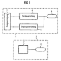
- FIG. 1 are a data transceiver 1 and a portable data carrier 2 is shown in a schematic representation.
- the data transceiver 1 has one Power supply 3 and a receiving device 5 and one Transmitter 4 on. Both the transmitter 4 and the receiving device 5 are also connected to one another by an antenna 6 connected. In the simplest case, the antenna 6 is one arbitrarily shaped conductor loop. Both the sending device 4 and the receiving device 5 are connected to the power supply 3 connected.
- the transmitter device 4 including a quartz, an oscillator, a Modulator and a power amplifier.
- the receiving device 5 consists z. B. from a bandpass filter, an amplifier and a demodulator. Because the exact structure of both from the transmitting device 4 as well as from the receiving device 5 are not essential to the inventive concept not discussed in more detail.
- the portable data carrier 2 has a data carrier antenna 8 and a circuit arrangement 7.
- the circuit arrangement 7 can, for example, as an integrated semiconductor chip or but can also be designed in the form of a discrete circuit.
- the circuit arrangement 7 can, for. B. a matching circuit, the connects the circuit arrangement 7 to the data carrier antenna 8, exhibit.
- the circuit arrangement 7 a modulator, a demodulator, a microprocessor or but also include a memory. Because the exact design the circuit arrangement 7 is not essential for the invention is not discussed in more detail here.
- the mode of operation of the data transceiver is as follows:
- the transmitter 4 generates a signal with a predetermined frequency, which will be referred to as the operating frequency f o in the future.
- This signal is passed on from the transmitting device 4 to the antenna 6 of the data transmitting / receiving device. If the portable data carrier 2 is in the effective range of the data transceiver 1, the signal generated by the antenna 6 is transmitted to the portable data carrier 2, where it is converted into an induced voltage by the data carrier antenna 8.
- This induced voltage ensures both the operating voltage of the circuit arrangement 7 and likewise contains the information to be transported, which is processed by the circuit arrangement 7.
- FIG. 2a shows an equivalent circuit diagram of a data transmission / reception device 1.
- the antenna itself has an inductive reactance.
- a simple linear equivalent circuit diagram of a portable data carrier 2 is shown in FIG. 2b.
- the energy supply 3 and the entire circuitry between the energy supply and the antenna 6 of the data transceiver 1 can be connected to an equivalent voltage source U F 0 (source voltage, in the time domain ⁇ F 0 * sin (2 ⁇ ft )) and an internal impedance Z FA can be reduced.
- the internal impedance can consist of any interconnection of resistors R, inductors L and capacitors C.
- the antenna 6 is modeled as an inductor L F and a loss resistance R LF .
- the equivalent voltage source U F0 and the internal impedance Z FA as well as the inductance L F and the loss resistance R LF of the antenna 6 are interconnected in the form of a series connection.
- the equivalent circuit diagram in FIG. 2a shows the data transceiver 1 in a state in which there is no portable data carrier within the effective range. This means that there is no coupling between the antenna of the data transceiver and an antenna of a portable data carrier.
- the data carrier antenna 8 is modeled from a loss resistance R LT and an inductance L T.
- the resistor R LT and the coil L T are connected together in series.
- the circuit arrangement 7, the z. B. can be designed as an integrated semiconductor chip, can be simplified from a loss resistance R T and a capacitance C T connected in parallel.
- the circuit arrangement 7 is connected in parallel with the data carrier antenna 8.
- the portable data carrier 2 is in a state in which there is no coupling between the antennas of the data transceiver or another portable data carrier.
- the portable data carrier 2 exhibits predominantly capacitive behavior due to the size of the capacitance C T.
- the reactive component is this impedance 0.
- the coupling factor can become a maximum of 1. With infinite Distance becomes the coupling factor 0.
- the first embodiment of the invention is a free one Choice of the impedance of the antenna circuit 6 provided, one Adaptation to the characteristic impedance of a line between the Antenna 6 and the power supply 3 is not necessary. Specifically, this means that the antenna 6 and the power supply 3 are connected to each other and therefore the Total impedance of the antenna circuit have a reactive component may. Under a defined connection of the antenna 6 with the power supply 3 can be a cable of known length can be understood or one next to each other arranged connection between antenna and transmission or Receiving device so that the line between the antenna 6 and the power supply 3 is minimal.
- the predominantly capacitive impedance Z T of the series resonant circuit of the data carrier appears in the antenna circuit of the data transceiver as inductive impedance Z FT . Since the magnitude of the transformed impedance Z FT is very much smaller than the impedance Z F of the antenna circuit, the reaction to the antenna current is only very small. The antenna current with a data carrier in the active field therefore only decreases slightly compared to the antenna current when there is no data carrier in the active field.
- the impedances couple the data carriers to one another. Coupling the impedances of the data carriers changes their impedance Z T , which, when the data carriers are strongly coupled to one another, has predominantly inductive behavior. This predominantly inductive impedance appears in the antenna circuit as capacitive impedance Z FT . In the inductive tuning of the total impedance of the antenna circuit, the capacitive impedance Z FT partially compensates for the inductive impedance Z F , so that in the worst case a strong coupling of the data carriers to one another and a maximum distance of the
- Data carrier to the reader is a current increase in the antenna circuit results.
- the total impedance Z F of the antenna circuit of the data transceiver is capacitively matched, a current increase can be set when the data carrier is inserted.
- the predominantly capacitive impedance Z T of the data carrier again appears in the antenna circuit as a predominantly inductive impedance.
- the capacitive impedance of the antenna circuit can be set so that the greatest current increase results for a maximum distance of the data carrier.
- the system properties are determined from the number of data carriers in the active field, in which a data exchange between the data carrier and the data transceiver without any problems should work, as well as the maximum distance to Antenna of the data transceiver up to one Coupling between data carriers and the data transceiver should be possible.
- the optimization potential is the largest with the so-called closed coupling systems.
- the circuit arrangement 7 of the portable data carrier 2 does not have its own energy supply, the operating voltage U T necessary for the circuit arrangement 7 must be utilized by the signal in the data carrier antenna induced by the data transceiver.
- the so-called resonance exaggeration by the series resonant circuit of the capacitance C T and the inductance L T of the portable data carrier 2 is used.
- the data carriers 2 couple not only to the antenna 6, but also to one another.
- This coupling causes the resonance frequency of each data carrier oscillating circuit to drop.
- the lower the resonance frequency the greater the more the data carriers couple to each other, ie the closer the distance between the two data carriers and the more data carriers are in the effective field.
- the resonance frequency of a data carrier can vary by a factor of 1 / due to the coupling of the data carriers to one another. N decrease, where N is the number of disks.
- the worst case would occur if the data carrier antennas were 0 cm apart and the coils were congruent. This can not occur in practice, since the antennas are usually in a housing z. B. are surrounded by a plastic card in a chip card.
- the voltage U T which is present at the input of the circuit arrangement 7 of the data carrier 2, is standardized to the voltage U TF induced in the data carrier antenna 8 by the antenna 6 of the data transceiver 1. It is advantageous for the operation of a data carrier that the ratio between U T and U TF is greater than 1. In this case, an adequate voltage supply to the circuit arrangement 7 is ensured even with correspondingly larger distances. If the data transmission / reception device is designed for exactly one data carrier, the resonance frequency of the data carrier is ideally matched to the intended frequency f 0 of the data transmission / reception device. In this case, the ratio between U T and U TF is greatest. If the data transmission / reception device is designed for a number of cards, the excessive resonance is only partially used.
- the resonance frequency of each data carrier is designed above the intended frequency f 0 . If there is a data carrier in the active field of the data transmission / reception device, the relationship between U T and U TF is at point 1 in FIG Disks are sinking. In this case, e.g. B. point 2 in the figure is reached. This is already below the predetermined frequency f 0 . The position of point 2 depends on how strong the coupling between the two data carriers is. This essentially depends on the distance between the two data carriers. Point 2 can therefore move further to the left or right on the drawn line. If a further, third data carrier is introduced into the active field, the resonance frequency of all data carriers drops further below the predetermined frequency f 0 and point 3 in the figure is reached. This point can also move along the line drawn in, depending on how the three data carriers are coupled to one another.
- the resonance frequency of the data carriers is therefore advantageously tuned above the predetermined frequency f 0 . This is equivalent to the fact that the reactive component of the impedance of a data carrier is capacitive. Each data carrier receives only a part of the possible voltage surge. In the example shown in FIG. 4, the voltage increase is then also present when two data carriers are coupled.
- FIG. 5 shows the equivalent circuit diagram of the data transceiver 1 according to the invention in accordance with the second solution.
- the data transmission / reception device in turn has an antenna 6, which is modeled from an effective resistor R F and an inductance L F.
- the active resistance R F and the inductance L F are connected in series.
- a matching circuit 10 is connected in parallel with the antenna 6, which can consist of any interconnection of capacitors C and inductors L.
- the matching circuit C consists of two capacitors C 1 and C 2 .
- the matching circuit 10 also has a resistor R, which is connected to the resistor R F of the antenna 6.
- the resistance R serves to limit the quality.
- the capacitor C 2 of the adapter circuit 10 is connected on the one hand to the resistor R of the adapter circuit 10 and to the inductance L F of the antenna 6.
- the capacitance C 1 is connected at the connection point between the resistor R and the capacitance C 2 .
- the other connection of the capacitance C 1 is connected to a line 9 and to the inductance L F of the antenna 6.
- the line 9 can, for. B. be a cable of unknown length, which connects the adapter circuit 10 with a power supply 3 and an internal impedance R W.
- the line of unknown length has a certain wave resistance, the z. B. is 50 ohms.
- the internal impedance R W is a purely ohmic resistance and is matched to the characteristic impedance of line 9.
- the adapter circuit 10 takes on the task of adapting the antenna 6 to the characteristic impedance of the line 9, ie the antenna 6 with the adapter circuit 10 is tuned to resonance.
- the inductive reactance of the antenna 6 is compensated for by the capacitors C 1 and C 2 of the adapter circuit 10.
- the internal resistance R W simulates the circuit arrangements of the transmitting device or the receiving device in a simplified manner.
- the resistor R of the matching circuit 10 is inserted to limit the quality so that the bandwidth required for modulating the intended frequency is achieved.
- an additional loss resistance is inserted between the resistance R and the resistance R F of the antenna 6 depending on the system requirements (number of data carriers, distance of the effective range). This means nothing other than that the resistance R of the matching circuit 10 u. U. is significantly increased. This increase in resistance R then leads to a reduction in the power requirement.
- R ⁇ k min k Max (2 ⁇ f 0 ) 2 L F L T 2 ⁇ B T - R F k min and k max are the functional limits (ie range) defined by the system requirements.
- the magnetic field generated by the data transceiver or by the antenna has so-called field gaps, which are caused by a periodic short-circuiting of the energy supply. These field gaps are used to transmit data to the portable data carrier.
- the antenna 6, the matching circuit 10 and the line 9 and the internal resistance R w form an oscillating circuit.
- the current through the antenna 6 or the alternating magnetic field therefore decay within this field gap.
- the rate of decay is determined by quality. If the quality of this resonant circuit is high, the antenna current or the magnetic field decays only slowly.
- a small quality therefore has the advantage that the data transfer to the disk 2 and the Data transmission / reception device 1 can run quickly.
- FIG. 6 shows the effect of an additional resistance on the frequency response.
- the amplitude of the antenna current or the magnetic field H is plotted on the y-axis, while the frequency f is shown on the x-axis.
- FIG. 6 shows the course of the frequency response in a data transceiver according to the prior art with a quality between 10 and 30.
- the frequency response shows the envelope of the amplitude of the antenna current or the magnetic field over the frequency.
- the frequency response according to the prior art has a high amplitude at the intended frequency f 0 and decreases symmetrically on both sides.
- a low quality has a flat frequency response, which means poor filtering of frequency sidebands.
- the actual information that is exchanged between the data carrier and the data transceiver is transmitted in a sideband symmetrically about the intended frequency f 0 . If the intended frequency f 0 is, for example, 13.56 MHz, the information is, for. B. transmitted in the sidebands ⁇ 100 kHz.
- the amplitude of these sidebands is limited by the quality. Compliance with the standard is made possible in part by the filtering effect of the quality, but in part by reducing the antenna current. In an arrangement according to the prior art, however, a reduction in the current means that the magnetic field is only sufficient within a short range to enable data transmission between the data carrier and the data transceiver.
- the filter effect is deteriorated. This means nothing other than that the frequency response has a flatter course to the side of the predetermined frequency f 0 . This poorer filter effect is more than compensated for by limiting the antenna current through the additional resistor R. At the same time, however, the range of the active field of the data transmission / reception device is not reduced by the reduced antenna current. This results from the fact that when a data carrier is inserted, the magnetic field declines significantly less than with an arrangement according to the prior art.
- the magnetic field is the distance of a Data carrier shown for data transmission / reception device.
- Figure 7 shows a comparison of the magnetic Field between an arrangement according to the prior art and the data transmission / reception device according to the invention.
- Curves 1 and 2 show the strength of the magnetic field, if there is no data carrier in the effective field of the data transmission / reception device located. Because of the larger current through the antenna of the data transceiver the magnetic field of a data transceiver according to the prior art much stronger than that device according to the invention.
- Curve 1 shows the field course an arrangement according to the prior art
- curve 2 shows a course according to the invention.
- the magnetic field must exceed a value H min so that data can be exchanged between the data carrier and the data transceiver. Up to a point X design, the magnetic field must be greater than or equal to the minimum required magnetic H min .
- the current through the data transceiver according to the invention is dimensioned so that the magnetic field slightly exceeds the minimum field strength H min at the required maximum range X design .
- the magnetic field in a data transceiver according to the prior art is significantly higher due to the high current through the antenna in idle. If a data carrier is introduced into the active field of the data transceiver, the antenna current drops very sharply due to the coupling, in an arrangement according to the prior art, which results in a strong reduction in the magnetic source field (curve 1').
- the antenna current can therefore be cut off, ie data exchange between the data transceiver and the data carrier is no longer possible.
- the magnetic Field is therefore when inserting a data carrier in the effective range of the data transmission / reception device only a little compared to the field course with no data carrier reduced.
- the curve 2 ' the field course with a disk reproduces in the effective range, is therefore mainly small x higher than the magnetic field profile for a device according to the prior art (curve 1 ').
- Chip cards are used as portable data carriers which, for example, have the following parameters.
- the antenna of the data transceiver has dimensions similar to that of the chip cards.
- the inductance of the antenna of the data transceiver is L F ⁇ 2.3 ⁇ H, the chip cards have to work in a range up to 1 cm.
- the maximum power consumption of the antenna circuit from 80 mW to 30 mW. hereby the necessary current through the antenna of the data transmission / reception device decreases from 80 mA to 25 mA.
- the optimal value of the additional loss resistance or the additional inductive reactance in the antenna can only be done through a complex optimization calculation can be found, the boundary conditions being determined by the system requirements (minimum and maximum range, number of the maps, map properties, possibly given Antenna, operating frequency, etc.) are specified.
- tuning the antenna to resonance proves according to the prior art as the most unfavorable solution.
- tuning the antenna to resonance proves according to the prior art as the most unfavorable solution.
- For systems with large required ranges and associated great performance of the antenna coil is one Optimization is difficult because the inevitable loss resistances that occur can be greater than the optimally calculated.
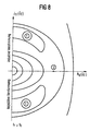
- FIG. 1 The result of a simulation calculation is shown in FIG. Lines of the same power consumption of the energy supply are shown in idle mode, ie with different designs of the active resistance and / or the inductive reactance of the antenna of the data transmission / reception device.
- the real part of the antenna impedance is plotted on the x-axis, while the imaginary part of the antenna impedance is shown on the y-axis.
- the results shown apply to a resonance frequency of the data carrier which is above the predetermined frequency f 0 of the data transceiver.
- the antenna tuned to resonance.
- the impedance the antenna only has an active component.
- active components in an antenna according to the state of the Technology implemented with low loss resistances This The point of high power consumption is on the x-axis close to the origin. If you continue walking on the x-axis right, d. H. you increase the loss resistance of the antenna, so less and less power is needed.
- the minimal Power consumption is reached at a point 2 that one Has resistance, according to the formula described above is calculated. If you continue over point 2 on the x-axis to the right, d. H. the loss resistance becomes even further increases, the power consumption increases again when idling on.
- a point on the x-axis corresponds to one on resonance tuned antenna.
- the invention makes it possible, with minimal circuit complexity, an inexpensive performance reduction when generating a magnetic alternating field of a data transceiver for the operation of at least one data carrier perform.
- the optimum can only be achieved in both proposed variants through optimization based on the upcoming system properties being found.
- the optimization potential is largest for so-called closed coupled systems.
Description
- Figur 1
- den schematischen Aufbau einer Daten-Sende/Empfangsvorrichtung sowie eines tragbaren Daten-trägers
- Figur 2a und 2b
- die vereinfachten linearen Ersatzschaltbilder einer Daten-Sende-/ Empfangsvorrichtung sowie eines tragbaren Datenträgers,
- Figur 3a
- das Ersatzschaltbild der Daten-Sende/Empfangs-vorrichtung, wenn sich ein tragbarer Datenträger im Wirkbereich befindet,
- Figur 3b
- ein Ersatzschaltbild eines tragbaren Datenträgers,der sich im Wirkbereich der Daten-Sende/Empfangsvorrichtung befindet,
- Figur 4
- den normierten Verlauf der Betriebsspannung eines oder mehrerer tragbarer Datenträger über der Resonanzfrequenz,
- Figur 5
- ein Ersatzschaltbild der erfindungsgemäßen Daten-Sende-/Empfangsvorrichtung, bei der ein zusätzlicher Widerstand zwischen die Antenne und die Anpaßschaltung eingebracht ist,
- Figur 6
- die Auswirkung auf den Frequenzgang bei verschiedenen Widerständen zwischen der Antenne und der Anpaßschaltung,
- Figur 7
- die Darstellung des magnetischen Feldverlaufs über dem Abstand der Datenträger zu der Daten-Sende/Empfangsvorrichtung und
- Figur 8
- die Darstellung der Leistungsaufnahme der Energieversorgung bei unterschiedlicher Auslegung von Wirkwiderstand und/oder Blindwiderstand der Antenne.
ÛF 0*sin(2πft)) und eine Innenimpedanz ZFA reduziert werden. Die Innenimpedanz kann aus einer beliebigen Zusammenschaltung von Widerstanden R, Induktivitäten L und Kapazitäten C bestehen. Die Antenne 6 wird als eine Induktivität LF und einem Verlustwiderstand RLF modelliert. Die Ersatzspannungsquelle UF0 und die Innenimpedanz ZFA sowie die Induktivität LF und der Verlustwiderstand RLF der Antenne 6 sind in Form einer Reihenschaltung miteinander verschaltet. Das Ersatzschaltbild in Figur 2a gibt die Daten-Sende-/Empfangsvorrichtung 1 in einem Zustand wieder, in der kein tragbarer Datenträger innerhalb des Wirkbereichs ist. Dies bedeutet es ist keine Verkopplung zwischen der Antenne der Daten-Sende-/Empfangsvorrichtung und einer Antenne eines tragbaren Datenträgers vorhanden.
- ω:
- Kreisfrequenz (=2πf),
- j:
- imaginäre Einheit und
- M:
- Gegeninduktivität.
- generelle Reduzierung des Antennenstromes
- spezielle Modulationsverfahren
- Filterwirkung (hohes Q).
Die Begrenzung der Seitenbänder durch Filterwirkung ist nur begrenzt möglich, da sonst Information weggefiltert wird.
Claims (4)
- Vorrichtung mit einer Daten-Sende-/Empfangsvorrichtung (1) und mindestens einem tragbaren Datenträger (2) zum kontaktlosen Übertragen von Daten zwischen der Daten-Sende/Empfangsvorrichtung (1) und dem mindestens einen tragbaren Datenträger (2),
wobei die Daten-Sende-/Empfangsvorrichtung (1)und wobei der tragbare Datenträger (2)eine Sendevorrichtung (4) zum Erzeugen eines ersten Signals mit einer vorgegebenen Frequenz,eine Empfangsvorrichtung (5) zum Empfangen eines Signals mit einer vorgegebenen Frequenz,eine impedanztransformierte Antenne (6), die mit der Sendevorrichtung (4) und der Empfangsvorrichtung (5) verbunden ist undeine Energieversorgung (3) aufweist,wobei die Antenne (6) der Daten-Sende-/Empfangsvorrichtung (1) eine Gesamtimpedanz aus einem Blindwiderstand BF ungleich 0 und einem ohmschen Verlustwiderstand RF aufweist, wenn kein tragbarer Datenträger (2) induktiv mit der Antenne (6) verbunden ist.eine Datenträger-Antenne (8) zum Empfangen oder Senden eines induzierten Signals undeine mit der Datenträger-Antenne (8) verbundene Schaltungsanordnung (7) zum Verarbeiten des induzierten Signals und Erzeugen eines Signals aufweist, welches zur Antenne (6) der Daten-Sende-/Empfangsvorrichtung (1) gesendet wird, - Vorrichtung zum kontaktlosen Übertragen von Daten nach Patentanspruch 1,
wobei zwischen der Antenne (6) und der Sendevorrichtung 4 bzw. der Empfangsvorrichtung (5) ein zusätzlicher Widerstand vorgesehen ist. - Vorrichtung zum kontaktlosen Übertragen von Daten nach Patentanspruch 2,
wobei die Daten-Sende-/Empfangsvorrichtung (1) eine Anpaßschaltungsanordnung (10) zwischen der Antenne (6) und der Sendevorrichtung (4) bzw. der Empfangsvorrichtung (5) aufweist. - Vorrichtung zum kontaktlosen Übertragen von Daten nach Patentanspruch 1, 2 oder 3,
wobei die Antenne (6) und die Sendevorrichtung (4) bzw. die Empfangsvorrichtung (5) über eine Verbindung bekannter Länge verbunden sind.
Priority Applications (1)
| Application Number | Priority Date | Filing Date | Title |
|---|---|---|---|
| EP01121395A EP1164532B1 (de) | 1998-05-15 | 1999-05-11 | Vorrichtung zur kontaktlosen Übertragung von Daten |
Applications Claiming Priority (5)
| Application Number | Priority Date | Filing Date | Title |
|---|---|---|---|
| DE19821909 | 1998-05-15 | ||
| DE19821909 | 1998-05-15 | ||
| DE19845065A DE19845065A1 (de) | 1998-05-15 | 1998-09-30 | Vorrichtung zur kontaktlosen Übertragung von Daten |
| DE19845065 | 1998-09-30 | ||
| PCT/DE1999/001412 WO1999060509A1 (de) | 1998-05-15 | 1999-05-11 | Vorrichtung zur kontaktlosen übertragung von daten |
Related Child Applications (1)
| Application Number | Title | Priority Date | Filing Date |
|---|---|---|---|
| EP01121395A Division EP1164532B1 (de) | 1998-05-15 | 1999-05-11 | Vorrichtung zur kontaktlosen Übertragung von Daten |
Publications (2)
| Publication Number | Publication Date |
|---|---|
| EP1076876A1 EP1076876A1 (de) | 2001-02-21 |
| EP1076876B1 true EP1076876B1 (de) | 2003-04-16 |
Family
ID=26046221
Family Applications (2)
| Application Number | Title | Priority Date | Filing Date |
|---|---|---|---|
| EP01121395A Expired - Lifetime EP1164532B1 (de) | 1998-05-15 | 1999-05-11 | Vorrichtung zur kontaktlosen Übertragung von Daten |
| EP99934466A Expired - Lifetime EP1076876B1 (de) | 1998-05-15 | 1999-05-11 | Vorrichtung zur kontaktlosen übertragung von daten |
Family Applications Before (1)
| Application Number | Title | Priority Date | Filing Date |
|---|---|---|---|
| EP01121395A Expired - Lifetime EP1164532B1 (de) | 1998-05-15 | 1999-05-11 | Vorrichtung zur kontaktlosen Übertragung von Daten |
Country Status (13)
| Country | Link |
|---|---|
| US (1) | US6533178B1 (de) |
| EP (2) | EP1164532B1 (de) |
| JP (1) | JP2002516438A (de) |
| KR (1) | KR100634631B1 (de) |
| CN (1) | CN1255754C (de) |
| AT (2) | ATE237845T1 (de) |
| BR (1) | BR9911055A (de) |
| DE (3) | DE19845065A1 (de) |
| ES (1) | ES2197657T3 (de) |
| MX (1) | MXPA00011254A (de) |
| RU (1) | RU2213370C2 (de) |
| UA (1) | UA57139C2 (de) |
| WO (1) | WO1999060509A1 (de) |
Families Citing this family (43)
| Publication number | Priority date | Publication date | Assignee | Title |
|---|---|---|---|---|
| JP2001168618A (ja) * | 1999-12-08 | 2001-06-22 | Smart Card Technologies:Kk | 無接触形icカードシステムにおけるリードライタ用のアンテナ装置 |
| DE60208047T2 (de) * | 2001-08-03 | 2006-08-24 | Koninklijke Philips Electronics N.V. | Transponder mit energiesparmodus während belastungsmodulation |
| WO2004023652A1 (en) * | 2002-09-05 | 2004-03-18 | Koninklijke Philips Electronics N.V. | Device comprising two mutually adapted impedances for the purpose of power transmission |
| TWI226588B (en) * | 2003-04-23 | 2005-01-11 | Winbond Electronics Corp | Contactless radio frequency magnetic field data transmission card and associated application system |
| US7825543B2 (en) | 2005-07-12 | 2010-11-02 | Massachusetts Institute Of Technology | Wireless energy transfer |
| JP4921466B2 (ja) | 2005-07-12 | 2012-04-25 | マサチューセッツ インスティテュート オブ テクノロジー | 無線非放射型エネルギー転送 |
| DE102005057546B4 (de) * | 2005-12-01 | 2007-08-16 | Kathrein-Austria Ges.M.B.H. | Verfahren und Vorrichtung zur kontaktlosen Übertragung von Daten von einer Vielzahl von Datenträgern, vorzugsweise in Form von RFID-Tags |
| GB2446622A (en) | 2007-02-14 | 2008-08-20 | Sharp Kk | Wireless interface |
| KR101159565B1 (ko) * | 2007-08-13 | 2012-06-26 | 퀄컴 인코포레이티드 | 장거리 저주파 공진기 및 재료 |
| US20090070691A1 (en) | 2007-09-12 | 2009-03-12 | Devicefidelity, Inc. | Presenting web pages through mobile host devices |
| US9311766B2 (en) | 2007-09-12 | 2016-04-12 | Devicefidelity, Inc. | Wireless communicating radio frequency signals |
| US9304555B2 (en) * | 2007-09-12 | 2016-04-05 | Devicefidelity, Inc. | Magnetically coupling radio frequency antennas |
| US8070057B2 (en) | 2007-09-12 | 2011-12-06 | Devicefidelity, Inc. | Switching between internal and external antennas |
| US8915447B2 (en) * | 2007-09-12 | 2014-12-23 | Devicefidelity, Inc. | Amplifying radio frequency signals |
| US20100182207A1 (en) * | 2007-09-27 | 2010-07-22 | Kazuhiko Miyata | Antenna device, display device substrate, liquid crystal display unit, display system, method for manufacturing antenna device and method for manufacturing display device substrate |
| JP2009176027A (ja) * | 2008-01-24 | 2009-08-06 | Toshiba Corp | 無線通信装置及び無線通信システム |
| US8855554B2 (en) * | 2008-03-05 | 2014-10-07 | Qualcomm Incorporated | Packaging and details of a wireless power device |
| CN102099958B (zh) * | 2008-05-14 | 2013-12-25 | 麻省理工学院 | 包括干涉增强的无线能量传输 |
| JP4671001B2 (ja) * | 2008-07-04 | 2011-04-13 | 株式会社村田製作所 | 無線icデバイス |
| ES2353569T3 (es) * | 2008-07-29 | 2011-03-03 | ODU- STECKVERBINDUNGSSYSTEME GMBH & CO. KG | Método y sistema para transmitir inductivamente energía e información. |
| EP2345100B1 (de) | 2008-10-01 | 2018-12-05 | Massachusetts Institute of Technology | Effiziente nahfeld-drahtlosenergieübertragung anhand adiabatischer systemveränderungen |
| JP2010130311A (ja) * | 2008-11-27 | 2010-06-10 | Sony Corp | 通信装置、通信方法、プログラム、および通信システム |
| US8497658B2 (en) | 2009-01-22 | 2013-07-30 | Qualcomm Incorporated | Adaptive power control for wireless charging of devices |
| TWM383785U (en) * | 2010-01-15 | 2010-07-01 | Gershin Electronics Co Ltd | Keychain drive retractable apparatus |
| US8313028B2 (en) * | 2010-02-17 | 2012-11-20 | On Track Innovations Ltd. | Multiple antenna reading system suitable for use with contactless transaction devices |
| US8195236B2 (en) | 2010-06-16 | 2012-06-05 | On Track Innovations Ltd. | Retrofit contactless smart SIM functionality in mobile communicators |
| US8424757B2 (en) | 2010-12-06 | 2013-04-23 | On Track Innovations Ltd. | Contactless smart SIM functionality retrofit for mobile communication device |
| KR101055448B1 (ko) | 2011-03-04 | 2011-08-08 | 삼성전기주식회사 | 통신 기능이 구비된 무선전력 송수신 장치 및 그 무선전력 송수신 방법 |
| JP5950549B2 (ja) * | 2011-03-30 | 2016-07-13 | デクセリアルズ株式会社 | アンテナ装置、通信装置 |
| CN103178328A (zh) * | 2011-12-23 | 2013-06-26 | 北京交大思诺科技有限公司 | 缩小型车载天线及其设计方法 |
| JP5997456B2 (ja) * | 2012-02-17 | 2016-09-28 | 学校法人慶應義塾 | 無線給電装置 |
| US9217323B2 (en) | 2012-09-24 | 2015-12-22 | Schlumberger Technology Corporation | Mechanical caliper system for a logging while drilling (LWD) borehole caliper |
| US20140083770A1 (en) * | 2012-09-24 | 2014-03-27 | Schlumberger Technology Corporation | System And Method For Wireless Drilling And Non-Rotating Mining Extenders In A Drilling Operation |
| US9206644B2 (en) * | 2012-09-24 | 2015-12-08 | Schlumberger Technology Corporation | Positive displacement motor (PDM) rotary steerable system (RSS) and apparatus |
| US20140083769A1 (en) * | 2012-09-24 | 2014-03-27 | Schlumberger Technology Corporation | Coiled Tube Drilling Bottom Hole Assembly Having Wireless Power And Data Connection |
| US9217289B2 (en) | 2012-09-24 | 2015-12-22 | Schlumberger Technology Corporation | Casing drilling bottom hole assembly having wireless power and data connection |
| US9217299B2 (en) * | 2012-09-24 | 2015-12-22 | Schlumberger Technology Corporation | Drilling bottom hole assembly having wireless power and data connection |
| US20140084696A1 (en) * | 2012-09-24 | 2014-03-27 | Schlumberger Technology Corporation | System And Method For Power Transmission In A Bottom Hole Assembly |
| US20140084946A1 (en) * | 2012-09-24 | 2014-03-27 | Schlumberger Technology Corporation | System And Method For Wireless Power And Data Transmission In A Rotary Steerable System |
| AT515401B1 (de) * | 2014-02-03 | 2016-04-15 | Seibersdorf Labor Gmbh | Abschirmelement zum Anbringen auf einem Gegenstand |
| RU2748174C2 (ru) * | 2019-07-16 | 2021-05-20 | Дмитрий Александрович Полетаев | Способ бесконтактной передачи данных |
| CN115204204B (zh) * | 2022-09-19 | 2022-12-02 | 江苏省质量和标准化研究院 | 基于mt-bp电磁感知的uhf多标签自适应识读方法及系统 |
| CN115865225B (zh) * | 2023-02-28 | 2024-02-20 | 北京紫光青藤微系统有限公司 | 用于确定射频设备异常的方法、装置、电子装置及设备 |
Family Cites Families (13)
| Publication number | Priority date | Publication date | Assignee | Title |
|---|---|---|---|---|
| US4480154A (en) * | 1980-12-15 | 1984-10-30 | Klee Maurice M | Automatic telephone silencer |
| GB2208025B (en) * | 1985-04-10 | 1989-06-21 | Gen Electric Co Plc | Transaction system |
| NL8803170A (nl) * | 1988-12-27 | 1990-07-16 | Nedap Nv | Identificatiesysteem. |
| US5047007A (en) * | 1989-12-22 | 1991-09-10 | Medtronic, Inc. | Method and apparatus for pulsed iontophoretic drug delivery |
| US5241160A (en) * | 1990-12-28 | 1993-08-31 | On Track Innovations Ltd. | System and method for the non-contact transmission of data |
| US5418353A (en) * | 1991-07-23 | 1995-05-23 | Hitachi Maxell, Ltd. | Non-contact, electromagnetically coupled transmission and receiving system for IC cards |
| US5287112A (en) * | 1993-04-14 | 1994-02-15 | Texas Instruments Incorporated | High speed read/write AVI system |
| NL9301169A (nl) * | 1993-07-05 | 1995-02-01 | Nedap Nv | Snelle communicatie naar een programmeerbaar identificatielabel. |
| US5461215A (en) * | 1994-03-17 | 1995-10-24 | Massachusetts Institute Of Technology | Fluid cooled litz coil inductive heater and connector therefor |
| JP2698766B2 (ja) * | 1995-01-11 | 1998-01-19 | ソニーケミカル株式会社 | 非接触式icカードシステム用送受信装置 |
| WO1998011504A1 (de) * | 1996-09-12 | 1998-03-19 | Fraunhofer-Gesellschaft zur Förderung der angewandten Forschung e.V. | Passiver transponder |
| JPH10203066A (ja) * | 1997-01-28 | 1998-08-04 | Hitachi Ltd | 非接触icカード |
| IL123949A (en) * | 1998-04-03 | 2001-07-24 | On Track Innovations Ltd | Data transaction card having extended range |
-
1998
- 1998-09-30 DE DE19845065A patent/DE19845065A1/de not_active Withdrawn
-
1999
- 1999-05-11 WO PCT/DE1999/001412 patent/WO1999060509A1/de active IP Right Grant
- 1999-05-11 KR KR1020007012823A patent/KR100634631B1/ko not_active IP Right Cessation
- 1999-05-11 ES ES99934466T patent/ES2197657T3/es not_active Expired - Lifetime
- 1999-05-11 MX MXPA00011254A patent/MXPA00011254A/es active IP Right Grant
- 1999-05-11 DE DE59905080T patent/DE59905080D1/de not_active Expired - Lifetime
- 1999-05-11 AT AT99934466T patent/ATE237845T1/de active
- 1999-05-11 EP EP01121395A patent/EP1164532B1/de not_active Expired - Lifetime
- 1999-05-11 BR BR9911055-5A patent/BR9911055A/pt not_active IP Right Cessation
- 1999-05-11 JP JP2000550050A patent/JP2002516438A/ja active Pending
- 1999-05-11 EP EP99934466A patent/EP1076876B1/de not_active Expired - Lifetime
- 1999-05-11 RU RU2000131621/09A patent/RU2213370C2/ru not_active IP Right Cessation
- 1999-05-11 DE DE59911459T patent/DE59911459D1/de not_active Expired - Lifetime
- 1999-05-11 CN CNB998086177A patent/CN1255754C/zh not_active Expired - Fee Related
- 1999-05-11 AT AT01121395T patent/ATE287109T1/de active
- 1999-11-05 UA UA2000116455A patent/UA57139C2/uk unknown
-
2000
- 2000-11-15 US US09/713,485 patent/US6533178B1/en not_active Expired - Lifetime
Also Published As
| Publication number | Publication date |
|---|---|
| CN1255754C (zh) | 2006-05-10 |
| EP1164532A3 (de) | 2002-01-02 |
| JP2002516438A (ja) | 2002-06-04 |
| MXPA00011254A (es) | 2003-05-19 |
| ATE237845T1 (de) | 2003-05-15 |
| RU2213370C2 (ru) | 2003-09-27 |
| EP1076876A1 (de) | 2001-02-21 |
| DE59905080D1 (de) | 2003-05-22 |
| KR20010043643A (ko) | 2001-05-25 |
| EP1164532B1 (de) | 2005-01-12 |
| CN1309793A (zh) | 2001-08-22 |
| DE19845065A1 (de) | 1999-11-25 |
| ATE287109T1 (de) | 2005-01-15 |
| UA57139C2 (uk) | 2003-06-16 |
| ES2197657T3 (es) | 2004-01-01 |
| BR9911055A (pt) | 2001-02-06 |
| KR100634631B1 (ko) | 2006-10-16 |
| EP1164532A2 (de) | 2001-12-19 |
| DE59911459D1 (de) | 2005-02-17 |
| WO1999060509A1 (de) | 1999-11-25 |
| US6533178B1 (en) | 2003-03-18 |
Similar Documents
| Publication | Publication Date | Title |
|---|---|---|
| EP1076876B1 (de) | Vorrichtung zur kontaktlosen übertragung von daten | |
| DE60306073T2 (de) | Verfahren zur Anpassung der elektromagnetischen Kopplungscharakteristik in einem kontaktlosen Energieversorgungssystem, sowie ein kontaktloses Energieversorgungssystem | |
| EP1437816B1 (de) | Schaltungsanordnung zur Bereitstellung elektrischer Leistung aus einem elektromagnetischen Feld | |
| DE69630843T2 (de) | Anlage zum Fernaustausch von Informationen zwischen einem tragbaren passiven Objekt und einer Station, entsprechendes Objekt und Station | |
| EP1336158A1 (de) | Kontaktloser datenträger | |
| EP1224607B1 (de) | Verfahren zum auslesen und beschreiben von rfid-transpondern | |
| EP1026618B1 (de) | Transponder-Leseeinrichtung | |
| DE69936439T2 (de) | Kapazitive Modulation in einem elektromagnetischen Transponder | |
| DE10158442B4 (de) | Sende- und Empfangseinrichtung für eine kontaktlose Datenübertragung | |
| DE19923634A1 (de) | Sende- und Empfangseinrichtung | |
| DE60007291T2 (de) | Schaltungsanordnung zum empfangen und senden von daten mit induktiver kopplung | |
| EP1344178B1 (de) | Vorrichtung und verfahren zum gleichzeitigen auslesen von passiven induktiven transpondern | |
| DE69630558T2 (de) | Elektronisches Bauelement für eine kontaktlose passive Karte | |
| EP3001561A1 (de) | Antennenschaltung für nahfeld-antennen | |
| EP2141637B1 (de) | Tragbarer Datenträger mit aktiver Kontaktlosschnittstelle und Verfahren zum Betreiben | |
| WO2018007014A1 (de) | Datenträger mit zwei schwingkreisen | |
| WO2009135722A1 (de) | Rfid- transponder mit dualer schnittstelle | |
| DE60106938T2 (de) | Antenne zum erzeugen eines elektromagnetfeldes für transponder | |
| DE10357665A1 (de) | Schaltungsanordnung zur Bereitstellung elektrischer Leistung aus einem elektromagnetischen Feld | |
| DE102015102288B4 (de) | Chipkarten-Leseanordnung | |
| EP1190369B1 (de) | Kommunikationsendgerät | |
| WO2008000325A1 (de) | Chipkarte und verfahren zur herstellung einer chipkarte | |
| DE102018211016A1 (de) | Schaltung zur signaltechnischen Verbindung, Vorrichtung zur induktiven Übertragung von Energie sowie zur Signalübertragung sowie Verfahren zur Herstellung | |
| WO2002019250A1 (de) | Kommunikationsendgerät | |
| EP1480156A2 (de) | Vorrichtung zur Ausstrahlung von HF-Signalen, insbesondere in einem Identifikationssystem |
Legal Events
| Date | Code | Title | Description |
|---|---|---|---|
| PUAI | Public reference made under article 153(3) epc to a published international application that has entered the european phase |
Free format text: ORIGINAL CODE: 0009012 |
|
| 17P | Request for examination filed |
Effective date: 20001106 |
|
| AK | Designated contracting states |
Kind code of ref document: A1 Designated state(s): AT CH DE ES FR GB IT LI |
|
| 17Q | First examination report despatched |
Effective date: 20010306 |
|
| GRAG | Despatch of communication of intention to grant |
Free format text: ORIGINAL CODE: EPIDOS AGRA |
|
| GRAG | Despatch of communication of intention to grant |
Free format text: ORIGINAL CODE: EPIDOS AGRA |
|
| GRAH | Despatch of communication of intention to grant a patent |
Free format text: ORIGINAL CODE: EPIDOS IGRA |
|
| GRAH | Despatch of communication of intention to grant a patent |
Free format text: ORIGINAL CODE: EPIDOS IGRA |
|
| GRAA | (expected) grant |
Free format text: ORIGINAL CODE: 0009210 |
|
| AK | Designated contracting states |
Designated state(s): AT CH DE ES FR GB IT LI |
|
| REG | Reference to a national code |
Ref country code: GB Ref legal event code: FG4D Free format text: NOT ENGLISH |
|
| REG | Reference to a national code |
Ref country code: CH Ref legal event code: EP |
|
| REF | Corresponds to: |
Ref document number: 59905080 Country of ref document: DE Date of ref document: 20030522 Kind code of ref document: P |
|
| REG | Reference to a national code |
Ref country code: CH Ref legal event code: NV Representative=s name: INFINEON TECHNOLOGIES SCHWEIZ AG |
|
| GBT | Gb: translation of ep patent filed (gb section 77(6)(a)/1977) |
Effective date: 20030806 |
|
| REG | Reference to a national code |
Ref country code: ES Ref legal event code: FG2A Ref document number: 2197657 Country of ref document: ES Kind code of ref document: T3 |
|
| ET | Fr: translation filed | ||
| PLBE | No opposition filed within time limit |
Free format text: ORIGINAL CODE: 0009261 |
|
| STAA | Information on the status of an ep patent application or granted ep patent |
Free format text: STATUS: NO OPPOSITION FILED WITHIN TIME LIMIT |
|
| 26N | No opposition filed |
Effective date: 20040119 |
|
| PGFP | Annual fee paid to national office [announced via postgrant information from national office to epo] |
Ref country code: CH Payment date: 20040429 Year of fee payment: 6 |
|
| PGFP | Annual fee paid to national office [announced via postgrant information from national office to epo] |
Ref country code: ES Payment date: 20040519 Year of fee payment: 6 |
|
| PG25 | Lapsed in a contracting state [announced via postgrant information from national office to epo] |
Ref country code: IT Free format text: LAPSE BECAUSE OF NON-PAYMENT OF DUE FEES Effective date: 20050511 |
|
| PG25 | Lapsed in a contracting state [announced via postgrant information from national office to epo] |
Ref country code: ES Free format text: LAPSE BECAUSE OF NON-PAYMENT OF DUE FEES Effective date: 20050512 |
|
| PG25 | Lapsed in a contracting state [announced via postgrant information from national office to epo] |
Ref country code: LI Free format text: LAPSE BECAUSE OF NON-PAYMENT OF DUE FEES Effective date: 20050531 Ref country code: CH Free format text: LAPSE BECAUSE OF NON-PAYMENT OF DUE FEES Effective date: 20050531 |
|
| REG | Reference to a national code |
Ref country code: CH Ref legal event code: PL |
|
| REG | Reference to a national code |
Ref country code: ES Ref legal event code: FD2A Effective date: 20050512 |
|
| PGFP | Annual fee paid to national office [announced via postgrant information from national office to epo] |
Ref country code: DE Payment date: 20140715 Year of fee payment: 16 |
|
| REG | Reference to a national code |
Ref country code: FR Ref legal event code: PLFP Year of fee payment: 17 |
|
| PGFP | Annual fee paid to national office [announced via postgrant information from national office to epo] |
Ref country code: GB Payment date: 20150521 Year of fee payment: 17 |
|
| PGFP | Annual fee paid to national office [announced via postgrant information from national office to epo] |
Ref country code: FR Payment date: 20150521 Year of fee payment: 17 Ref country code: AT Payment date: 20150521 Year of fee payment: 17 |
|
| REG | Reference to a national code |
Ref country code: DE Ref legal event code: R119 Ref document number: 59905080 Country of ref document: DE |
|
| PG25 | Lapsed in a contracting state [announced via postgrant information from national office to epo] |
Ref country code: DE Free format text: LAPSE BECAUSE OF NON-PAYMENT OF DUE FEES Effective date: 20151201 |
|
| REG | Reference to a national code |
Ref country code: AT Ref legal event code: MM01 Ref document number: 237845 Country of ref document: AT Kind code of ref document: T Effective date: 20160511 |
|
| GBPC | Gb: european patent ceased through non-payment of renewal fee |
Effective date: 20160511 |
|
| PG25 | Lapsed in a contracting state [announced via postgrant information from national office to epo] |
Ref country code: AT Free format text: LAPSE BECAUSE OF NON-PAYMENT OF DUE FEES Effective date: 20160511 |
|
| REG | Reference to a national code |
Ref country code: FR Ref legal event code: ST Effective date: 20170131 |
|
| PG25 | Lapsed in a contracting state [announced via postgrant information from national office to epo] |
Ref country code: FR Free format text: LAPSE BECAUSE OF NON-PAYMENT OF DUE FEES Effective date: 20160531 |
|
| PG25 | Lapsed in a contracting state [announced via postgrant information from national office to epo] |
Ref country code: GB Free format text: LAPSE BECAUSE OF NON-PAYMENT OF DUE FEES Effective date: 20160511 |