EP1026439B1 - Kraftfahrzeugscheinwerfer - Google Patents
Kraftfahrzeugscheinwerfer Download PDFInfo
- Publication number
- EP1026439B1 EP1026439B1 EP00102585A EP00102585A EP1026439B1 EP 1026439 B1 EP1026439 B1 EP 1026439B1 EP 00102585 A EP00102585 A EP 00102585A EP 00102585 A EP00102585 A EP 00102585A EP 1026439 B1 EP1026439 B1 EP 1026439B1
- Authority
- EP
- European Patent Office
- Prior art keywords
- screen
- mobile
- headlamp
- optical axis
- dipped
- Prior art date
- Legal status (The legal status is an assumption and is not a legal conclusion. Google has not performed a legal analysis and makes no representation as to the accuracy of the status listed.)
- Expired - Lifetime
Links
- 230000003287 optical effect Effects 0.000 claims description 16
- 229910052736 halogen Inorganic materials 0.000 description 1
- 150000002367 halogens Chemical class 0.000 description 1
- 230000035899 viability Effects 0.000 description 1
Images


Classifications
-
- F—MECHANICAL ENGINEERING; LIGHTING; HEATING; WEAPONS; BLASTING
- F21—LIGHTING
- F21S—NON-PORTABLE LIGHTING DEVICES; SYSTEMS THEREOF; VEHICLE LIGHTING DEVICES SPECIALLY ADAPTED FOR VEHICLE EXTERIORS
- F21S41/00—Illuminating devices specially adapted for vehicle exteriors, e.g. headlamps
- F21S41/60—Illuminating devices specially adapted for vehicle exteriors, e.g. headlamps characterised by a variable light distribution
- F21S41/68—Illuminating devices specially adapted for vehicle exteriors, e.g. headlamps characterised by a variable light distribution by acting on screens
- F21S41/683—Illuminating devices specially adapted for vehicle exteriors, e.g. headlamps characterised by a variable light distribution by acting on screens by moving screens
- F21S41/689—Flaps, i.e. screens pivoting around one of their edges
-
- F—MECHANICAL ENGINEERING; LIGHTING; HEATING; WEAPONS; BLASTING
- F21—LIGHTING
- F21S—NON-PORTABLE LIGHTING DEVICES; SYSTEMS THEREOF; VEHICLE LIGHTING DEVICES SPECIALLY ADAPTED FOR VEHICLE EXTERIORS
- F21S41/00—Illuminating devices specially adapted for vehicle exteriors, e.g. headlamps
- F21S41/40—Illuminating devices specially adapted for vehicle exteriors, e.g. headlamps characterised by screens, non-reflecting members, light-shielding members or fixed shades
- F21S41/47—Attachment thereof
Definitions
- the present invention relates to a headlamp for motor vehicles, which can generate selectively a full light beam and a dipped/fog light beam.
- the headlamps which are fitted at present onto motor vehicles perform the full- and dipped-beam functions by means of a two-filament halogen lamp and substantially bifocal optics, or by means of two single-filament lamps, and separate optics.
- the headlamp comprises a bifocal reflector, along the optical axis of which, and more specifically at the focal point of which, there are disposed the two filaments of the lamp, which can be actuated alternately; an intermediate screen which is disposed facing one of the two filaments, and can intercept part of the light emitted by this filament, in order to obtain as output from the headlamp a dipped light beam which is provided with the corresponding cut-off (i.e.
- the light emitted by the second filament is used entirely for generation of the full light.
- two separate reflectors are provided, each for a single filament lamp, and are designed in order to obtain respectively a full light beam and a dipped light beam.
- the object of the present invention is to provide a headlamp which can be fitted to motor vehicles, which is at the same time simple, economical, and has a reduced size.
- a headlamp for motor vehicles which can generate selectively a full light beam and a dipped/fog light beam, As defined in Claim 1
- the intermediate screens comprise a fixed intermediate screen, which can define a light/dark demarcation line of the dipped/fog beam, and a mobile intermediate screen; the said intermediate screens are held together by means of a hinge which can permit rotation of the mobile intermediate screen.
- the mobile intermediate screen When the intermediate screens are in the first operating position, in order to permit passage of a light beam obtained from the lower reflecting part, the mobile intermediate screen is disposed substantially parallel to the optical axis, and substantially at right angles to the fixed intermediate screen, and when the intermediate screens are in the second operating position, in order to intercept a light beam from the lower reflecting part, the mobile intermediate screen is disposed substantially at right angles to the optical axis, and substantially aligned with the fixed intermediate screen.
- the solutions proposed are simple and economical, and provide the structure with a minimum size, and which can be adapted to different models of motor vehicles.
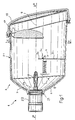
- 1 indicates as a whole a headlamp for motor vehicles, the substantial parts of which comprise: a reflector 2, which is subdivided into an upper reflecting area 3, and a lower reflecting area 4, and has an optical axis 5; a lamp/lamp-holder unit 19, which is disposed along the optical axis 5; a lens 7, which can converge a dipped/fog light beam; intermediate screens 9; and movement means 8, which are disposed on the exterior of a casing 24 which contains the reflector 2, the light source, the intermediate screens 9 and the lens 7.
- the movement means can move the intermediate screens 9 between a first operating position, in which the headlamp 1 can generate a full light beam ( figure 2 ), and a second operating position, in which the headlamp 1 can generate a dipped/fog light beam ( figure 1 ).
- the casing 24 is integral with the reflector 2, and defines a front aperture 17, which is closed by a transparent component 18, which can guarantee water-tightness of the reflector itself.
- the upper reflecting area 3 is of the mono-focal type, and the lower reflecting area 4 is of the complex type.
- the lamp/lamp-holder unit 19 extends through a circular cavity 20 which is provided in the rear part of the reflector 2 and comprises: a lamp 6 with a single filament, which can be of the incandescent or gas discharge type, and is disposed at least partially inside the concavity defined by the reflector 2; a lampholder tube 21, which has a substantially annular shape, is disposed co-axially relative to the axis 5, and can be fitted in a manner which is known, and is not illustrated for the sake of simplicity, in the circular cavity 20; and a support body 22, which has a substantially cylindrical shape.
- the lamp/lamp-holder unit 19 also comprises an electrical connection body (not shown) which is fitted to the rear of the support body 21.
- the lens 7 which can converge the dipped/fog light beam is disposed in a front position at the front reflecting area 3, and at right angles relative to the optical axis 5.
- the intermediate screens 9 are disposed at the lower reflecting area 4, and comprise a fixed intermediate screen 9a, which can define a light/dark demarcation line 25 (known as the cut-off), and has a shape pre-determined by the dipped/fog beam, and a mobile intermediate screen 9b.
- a fixed intermediate screen 9a which can define a light/dark demarcation line 25 (known as the cut-off), and has a shape pre-determined by the dipped/fog beam, and a mobile intermediate screen 9b.
- the mobile intermediate screen 9b In a first operating position, in order to permit passage of the light beam obtained from the lower reflecting part 4, the mobile intermediate screen 9b is disposed substantially parallel relative to the said optical axis 5, and substantially at right angles to the fixed intermediate screen 9a; in a second operating position, in order to intercept the light beam obtained from the lower reflecting part 4, the mobile intermediate screen 9b is disposed substantially at right angles to the optical axis 5, and substantially aligned with the fixed intermediate screen 9a.
- intermediate screens 9a and 9b are held together by means of a hinge 9c, which can permit rotation of the mobile intermediate screen 9b.
- the mobile intermediate screen 9b is integral with a lever 10.
- the movement means 8 comprise: an electro-magnet 11, which supports a mobile core 12, which defines a rod, the free end of which has a sphere 13; an arm 14, which on its first end defines a spherical cavity 13a, which can retain the sphere 13, whereas its second end defines a seat 15 which can accommodate the lever 10; and a helical spring 16 which is wound around the mobile core 12, one end 16a of which is secured to the arm 14, at a seat 14a, and the other end 16b of which is secured to the electro-magnet 11 at a seat 11a.
- the movement means 8 are secured to the exterior of the casing 24 which contains the reflector 2, the light source, the intermediate screens 9 and the lens 7, by means of a support frame 23.
- the headlamp 1 functions as follows.
- the movement means 8 are in the above-described dipped/fog condition ( figure 1 ; figure 5 ) and that consequently, the intermediate screens 9 are in the said second operating position, such that the mobile intermediate screen 9b can intercept the flow of light reflected by the lower reflecting part 4, thus providing a dipped or fog beam, according to the profile of the light/dark demarcation line 25.
- the movement means 8 are actuated such as to change to the full-beam condition ( figure 2; figure 5 ).
- the supply to the electro-magnet 11 is switched on, and makes the mobile core 12 contract.
- the mobile core 12 transmits the motion to the arm 14, which then exerts thrust on the lever 10 ( figure 5 ).
- the lever 10 gives rise to rotation of the mobile intermediate screen 9b, making it assume at its end of travel a position which is substantially parallel to the optical axis 5, and substantially at right-angles to the fixed intermediate screen 9a ( figure 2 ).
- the supply to the electro-magnet 11 is interrupted, such that the arm 14 is subjected to the return force of the spring 16, and returns to the initial position ( figure 5 ). Consequently, the arm 14 returns the lever 10 to the initial position ( figure 5 ).
- the mobile intermediate screen 9b is returned substantially at right-angles to the optical axis 5, and substantially aligned with the fixed intermediate screen 9a, in which position the headlamp generates a dipped/fog light beam ( figure 1 ).
Landscapes
- Engineering & Computer Science (AREA)
- General Engineering & Computer Science (AREA)
- Non-Portable Lighting Devices Or Systems Thereof (AREA)
Claims (6)
- Kraftfahrzeugscheinwerfer (1), der selektiv einen Fernlichtstrahl und einen Abblendlichtstrahl/Nebelscheinwerfer-Lichtstrahl erzeugen kann, und folgendes aufweist: eine einzelne Lichtquelle (6); einen Reflektor (2), der in einen oberen reflektierenden Bereich (3) und in einen unteren reflektierenden Bereich (4) unterteilt ist, und eine optische Achse (5) besitzt, entlang der die einzelne Lichtquelle angeordnet ist, welche aus folgendem besteht: einer Einfadenlampe (6); einer Linse (7), die in einer Position im rechten Winkel zu der optischen Achse (5) angeordnet ist, und die einen Abblendlichtstrahl/Nebelscheinwerfer-Lichtstrahl bündeln kann; und Zwischenabschirmungen (9a, 9b), um einen Teil des Lichts, das von der Lichtquelle abgegeben wird, abzufangen, wobei die Zwischenabschirmungen (9a, 9b) eine feste Zwischenabschirmung (9a) und eine bewegliche Zwischenabschirmung (9b) aufweisen, wobei die feste Zwischenabschirmung (9a) und die bewegliche Zwischenabschirmung (9b) mittels eines Scharniers (9c) zusammengehalten werden, das ein Drehen der beweglichen Zwischenabschirmung (9b) ermöglicht, und der Scheinwerfer auch Bewegungseinrichtungen (8) besitzt, die die bewegliche Zwischenabschirmung (9b) selektiv zwischen mindestens zwei verschiedenen Positionen bewegen können, wobei in der ersten Position ein Teil des Lichts nicht abgefangen wird, und in einer zweiten Position das Licht abgefangen werden kann, und wobei in Kombination:i)- die Zwischenabschirmungen (9a, 9b) beide vor dem unteren reflektierenden Bereich (4) des Reflektors (2) und unter der optischen Achse (5) in der ersten und zweiten Position der beweglichen Zwischenabschirmung (9b) angeordnet sind;ii)-die feste Zwischenabschirmung (9a) eine helle/dunkle Abgrenzungslinie (25) des Abblendlichtstrahls/Nebelscheinwerfer-Lichtstrahls definiert; undiii)-die Linse (7) vor dem oberen reflektierenden Bereich (3) angeordnet ist; wobei der Scheinwerfer
dadurch gekennzeichnet ist, dass:iv)-sich die feste Abschirmung (9a) auf der beweglichen Abschirmung (9b) befindet und letztere in der ersten Betriebsposition im wesentlichen parallel zu der optischen Achse (5) und im wesentlichen im rechten Winkel zu der festen Abschirmung (9a) angeordnet ist, während die bewegliche Abschirmung (9b) in der zweiten Betriebsposition im wesentlichen im rechten Winkel zu der optischen Achse (5) angeordnet ist und im wesentlichen mit der festen Abschirmung (9a) fluchtet;v)- der obere reflektierende Bereich (3) monofokal und der untere reflektierende Bereich (4) komplex ist;vi)-ein wesentlicher Teil der Linse (7) sich im wesentlichen über der optischen Achse (5) befindet;vii)-die feste Abschirmung (9a) die helle/dunkle Abgrenzungslinie (25) des Abblendlichtstrahls/Nebelscheinwerfer-Lichtstrahls definiert, wenn sich die bewegliche Abschirmung (9b) in ihrer zweiten Betriebsposition befindet. - Scheinwerfer nach Anspruch 1, dadurch gekennzeichnet, dass die bewegliche Zwischenabschirmung (9b) einen Hebel (10) besitzt, mit dem die bewegliche Zwischenabschirmung (9b) gedreht werden kann.
- Scheinwerfer nach Anspruch 2, dadurch gekennzeichnet, dass die Bewegungseinrichtungen (8) folgendes aufweisen:einen Elektromagneten (11) mit einem beweglichen Kern (12), der einen Stab definiert, dessen freies Ende eine Kugel (13) aufweist; einen Arm (14), der an seinem ersten Ende einen sphärischen Hohlraum (13a) bildet, der die Kugel (13) aufnehmen kann, während er an seinem zweiten Ende einen Sitz (15) bildet, der den Hebel (10) aufnehmen kann; und eine Schraubenfeder (16), die um den beweglichen Kern (12) herum gewickelt ist, wobei ein Ende (16a) an dem Arm (14) an einem Sitz (14a) und das andere Ende (16b) an dem Elektromagneten (11) an einem Sitz (11a) befestigt ist; wenn Strom zugeführt wird, kann der Elektromagnet (11) den Hebel (10) in einer Position halten, so dass sich die bewegliche Zwischenabschirmung (9b) in der ersten Position befindet, und die Feder (16) kann eine Rückholkraft erzeugen, um den Hebel (10) in eine Position zurückzuholen, so dass sich die bewegliche Zwischenabschirmung (9b) in der zweiten Position befindet.
- Scheinwerfer nach Anspruch 3, dadurch gekennzeichnet, dass die Bewegungseinrichtungen (8) außen an einem Gehäuse (24) befestigt sind, das den Reflektor (2), die Lichtquelle, die Zwischenabschirmungen (9) und die Linse (7) mittels eines Halterahmens (23) enthält.
- Scheinwerfer nach einem der vorhergehenden Ansprüche, dadurch gekennzeichnet, dass sich der Reflektor (2) an dem Gehäuse (24) befindet, und eine vordere Öffnung (17) bildet, die durch eine transparente Komponente (18) geschlossen wird, welche die Wasserdichtheit des Reflektors (2) garantieren kann.
- Scheinwerfer nach einem der vorhergehenden Ansprüche, dadurch gekennzeichnet, dass es sich bei der Einfadenlampe (6) um eine Glühlampe oder eine Gasentladungs-Lampe handeln kann.
Applications Claiming Priority (2)
| Application Number | Priority Date | Filing Date | Title |
|---|---|---|---|
| ITMI990239 | 1999-02-08 | ||
| IT1999MI000239A IT1307677B1 (it) | 1999-02-08 | 1999-02-08 | Proiettore per autoveicoli |
Publications (2)
| Publication Number | Publication Date |
|---|---|
| EP1026439A1 EP1026439A1 (de) | 2000-08-09 |
| EP1026439B1 true EP1026439B1 (de) | 2009-04-08 |
Family
ID=11381794
Family Applications (1)
| Application Number | Title | Priority Date | Filing Date |
|---|---|---|---|
| EP00102585A Expired - Lifetime EP1026439B1 (de) | 1999-02-08 | 2000-02-07 | Kraftfahrzeugscheinwerfer |
Country Status (4)
| Country | Link |
|---|---|
| US (1) | US6354721B1 (de) |
| EP (1) | EP1026439B1 (de) |
| DE (1) | DE60041942D1 (de) |
| IT (1) | IT1307677B1 (de) |
Families Citing this family (19)
| Publication number | Priority date | Publication date | Assignee | Title |
|---|---|---|---|---|
| FR2815310B1 (fr) * | 2000-10-12 | 2003-02-21 | Valeo Vision | Projecteur pour vehicule automobile a ecran d'occultation mobile |
| JP4008261B2 (ja) * | 2001-06-15 | 2007-11-14 | 株式会社小糸製作所 | 車両用前照灯 |
| DE10225566A1 (de) * | 2002-06-10 | 2004-03-04 | Hella Kg Hueck & Co. | Scheinwerfer für Fahrzeuge |
| FR2847657B1 (fr) * | 2002-11-21 | 2005-03-04 | Valeo Vision | Projecteur elliptique pour vehicule automobile emettant des faisceaux d'eclairage differents |
| DE10305624A1 (de) * | 2003-02-11 | 2004-08-19 | Volkswagen Ag | Scheinwerferanordnung für ein Fahrzeug zur Projektion variabler Lichtgeometrien |
| US7083304B2 (en) * | 2003-08-01 | 2006-08-01 | Illumination Management Solutions, Inc. | Apparatus and method of using light sources of differing wavelengths in an unitized beam |
| US7246917B2 (en) * | 2003-08-12 | 2007-07-24 | Illumination Management Solutions, Inc. | Apparatus and method for using emitting diodes (LED) in a side-emitting device |
| US7018078B2 (en) * | 2003-08-29 | 2006-03-28 | Guide Corporation | Light assembly with bending light |
| AU2004284713B2 (en) * | 2003-10-06 | 2007-11-15 | Signify Holding B.V. | Method and apparatus for light collection, distribution and zoom |
| US7036969B2 (en) * | 2003-12-04 | 2006-05-02 | Guide Corporation | Adverse weather headlamp system |
| FR2866413B1 (fr) * | 2004-02-13 | 2006-06-30 | Valeo Vision | Projecteur elliptique equipe d'un ecran d'occultation en matiere transparente. |
| CN1977127B (zh) * | 2004-03-30 | 2010-08-04 | 照明管理解决方案公司 | 用于改进的照明区域填充的设备和方法 |
| FR2883066B1 (fr) * | 2005-03-08 | 2007-05-11 | Valeo Vision Sa | Projecteur lumineux a plusieurs fonctions pour vehicule automobile |
| FR2884898B1 (fr) * | 2005-04-22 | 2007-08-31 | Valeo Vision Sa | Projecteur de vehicule automobile. |
| DE102005021706A1 (de) * | 2005-05-11 | 2006-11-16 | Hella Kgaa Hueck & Co. | Projektionsscheinwerfer für Fahrzeuge |
| US7357545B2 (en) | 2005-08-10 | 2008-04-15 | Visteon Global Technologies, Inc. | Multi-focal lens for bi-functional headlamp |
| US7950821B1 (en) | 2007-10-26 | 2011-05-31 | Georgitsis Anthony C | Auxiliary lighting systems |
| CN101639609B (zh) * | 2008-08-01 | 2012-03-14 | 鸿富锦精密工业(深圳)有限公司 | 便携式电子装置 |
| KR20120061682A (ko) * | 2010-12-03 | 2012-06-13 | 현대자동차주식회사 | 헤드램프 빔패턴 변환 구조 |
Family Cites Families (6)
| Publication number | Priority date | Publication date | Assignee | Title |
|---|---|---|---|---|
| DE3806658A1 (de) | 1988-03-02 | 1989-09-14 | Huppertz & Schneider Gmbh & Co | Scheinwerfer, insbesondere zum einsatz bei fahrzeugen unter tage |
| DE4002576C5 (de) | 1990-01-30 | 2005-06-02 | Automotive Lighting Reutlingen Gmbh | Scheinwerfer mit Abblend- und Fernlicht für Kraftfahrzeuge |
| DE19501173A1 (de) * | 1995-01-17 | 1996-07-18 | Bosch Gmbh Robert | Scheinwerfer für Fahrzeuge |
| DE19537838A1 (de) * | 1995-10-11 | 1997-04-17 | Bosch Gmbh Robert | Scheinwerfer für Fahrzeuge |
| DE19708109A1 (de) * | 1997-02-28 | 1998-09-03 | Hella Kg Hueck & Co | Scheinwerfer für Fahrzeuge |
| DE19708111A1 (de) | 1997-02-28 | 1998-09-03 | Hella Kg Hueck & Co | Fernbetätigbares Einstellsystem |
-
1999
- 1999-02-08 IT IT1999MI000239A patent/IT1307677B1/it active
-
2000
- 2000-02-07 EP EP00102585A patent/EP1026439B1/de not_active Expired - Lifetime
- 2000-02-07 DE DE60041942T patent/DE60041942D1/de not_active Expired - Fee Related
- 2000-02-07 US US09/499,306 patent/US6354721B1/en not_active Expired - Fee Related
Also Published As
| Publication number | Publication date |
|---|---|
| EP1026439A1 (de) | 2000-08-09 |
| ITMI990239A1 (it) | 2000-08-08 |
| DE60041942D1 (de) | 2009-05-20 |
| IT1307677B1 (it) | 2001-11-14 |
| US6354721B1 (en) | 2002-03-12 |
Similar Documents
| Publication | Publication Date | Title |
|---|---|---|
| US6354721B1 (en) | Headlamp for motor vehicles | |
| US6425683B1 (en) | Vehicle headlamp | |
| US6007223A (en) | Projector type lamp | |
| US6848814B2 (en) | Vehicle headlamp | |
| EP0979526B1 (de) | Fahrzeuglampe mit reduzierter blendung | |
| JP4983278B2 (ja) | 車両用灯具 | |
| JPS63158702A (ja) | 車輌用前照灯 | |
| JP2001236802A (ja) | 車両用前照灯 | |
| JPH052901A (ja) | 自動車のための前照灯 | |
| JP4422005B2 (ja) | 車両用前照灯 | |
| EP0579184B1 (de) | Scheinwerfer für Kraftfahrzeuge | |
| US4480296A (en) | Two-filament lamp for automobile headlight | |
| US7021804B2 (en) | Lamp assembly with multi-stage reflector | |
| US6742919B2 (en) | Discharge lamp and headlight for a motor vehicle | |
| US7033054B2 (en) | Lamp assembly with peripheral auxiliary function | |
| EP1003205B1 (de) | Lichtquelle mit Kolben und zwei Fäden | |
| JP2004006098A (ja) | 車両用前照灯 | |
| CA2235912C (en) | Vehicle lamp with light-trapping dome | |
| US20030090907A1 (en) | Switching device for selection of high/low beam | |
| GB2342150A (en) | Headlight for vehicles with a multi-faceted reflector for producing an asymmetric dipped beam. | |
| EP1054210B1 (de) | Scheinwerfer nach dem Projektionstyp für Kraftfahrzeuge | |
| JP2000251520A (ja) | 自動車用ランプ | |
| KR0170619B1 (ko) | 유압식 전조등 | |
| RU10238U1 (ru) | Световой прибор | |
| JP2004158231A (ja) | 車両用前照灯 |
Legal Events
| Date | Code | Title | Description |
|---|---|---|---|
| PUAI | Public reference made under article 153(3) epc to a published international application that has entered the european phase |
Free format text: ORIGINAL CODE: 0009012 |
|
| AK | Designated contracting states |
Kind code of ref document: A1 Designated state(s): DE ES FR GB |
|
| AX | Request for extension of the european patent |
Free format text: AL;LT;LV;MK;RO;SI |
|
| 17P | Request for examination filed |
Effective date: 20000912 |
|
| AKX | Designation fees paid |
Free format text: DE ES FR GB |
|
| 17Q | First examination report despatched |
Effective date: 20051205 |
|
| GRAP | Despatch of communication of intention to grant a patent |
Free format text: ORIGINAL CODE: EPIDOSNIGR1 |
|
| GRAS | Grant fee paid |
Free format text: ORIGINAL CODE: EPIDOSNIGR3 |
|
| GRAA | (expected) grant |
Free format text: ORIGINAL CODE: 0009210 |
|
| AK | Designated contracting states |
Kind code of ref document: B1 Designated state(s): DE ES FR GB |
|
| REG | Reference to a national code |
Ref country code: GB Ref legal event code: FG4D |
|
| REF | Corresponds to: |
Ref document number: 60041942 Country of ref document: DE Date of ref document: 20090520 Kind code of ref document: P |
|
| PG25 | Lapsed in a contracting state [announced via postgrant information from national office to epo] |
Ref country code: ES Free format text: LAPSE BECAUSE OF FAILURE TO SUBMIT A TRANSLATION OF THE DESCRIPTION OR TO PAY THE FEE WITHIN THE PRESCRIBED TIME-LIMIT Effective date: 20090719 |
|
| PLBE | No opposition filed within time limit |
Free format text: ORIGINAL CODE: 0009261 |
|
| STAA | Information on the status of an ep patent application or granted ep patent |
Free format text: STATUS: NO OPPOSITION FILED WITHIN TIME LIMIT |
|
| 26N | No opposition filed |
Effective date: 20100111 |
|
| GBPC | Gb: european patent ceased through non-payment of renewal fee |
Effective date: 20100207 |
|
| PG25 | Lapsed in a contracting state [announced via postgrant information from national office to epo] |
Ref country code: DE Free format text: LAPSE BECAUSE OF NON-PAYMENT OF DUE FEES Effective date: 20100901 |
|
| PG25 | Lapsed in a contracting state [announced via postgrant information from national office to epo] |
Ref country code: GB Free format text: LAPSE BECAUSE OF NON-PAYMENT OF DUE FEES Effective date: 20100207 |
|
| REG | Reference to a national code |
Ref country code: FR Ref legal event code: PLFP Year of fee payment: 17 |
|
| REG | Reference to a national code |
Ref country code: FR Ref legal event code: PLFP Year of fee payment: 18 |
|
| REG | Reference to a national code |
Ref country code: FR Ref legal event code: PLFP Year of fee payment: 19 |
|
| PGFP | Annual fee paid to national office [announced via postgrant information from national office to epo] |
Ref country code: FR Payment date: 20190123 Year of fee payment: 20 |