EP1025882A1 - Sicherheitsskibindung-Schuh-Kombination - Google Patents
Sicherheitsskibindung-Schuh-Kombination Download PDFInfo
- Publication number
- EP1025882A1 EP1025882A1 EP00810076A EP00810076A EP1025882A1 EP 1025882 A1 EP1025882 A1 EP 1025882A1 EP 00810076 A EP00810076 A EP 00810076A EP 00810076 A EP00810076 A EP 00810076A EP 1025882 A1 EP1025882 A1 EP 1025882A1
- Authority
- EP
- European Patent Office
- Prior art keywords
- cam
- bar
- assembly according
- parts
- shoe
- Prior art date
- Legal status (The legal status is an assumption and is not a legal conclusion. Google has not performed a legal analysis and makes no representation as to the accuracy of the status listed.)
- Granted
Links
Images


Classifications
-
- A—HUMAN NECESSITIES
- A63—SPORTS; GAMES; AMUSEMENTS
- A63C—SKATES; SKIS; ROLLER SKATES; DESIGN OR LAYOUT OF COURTS, RINKS OR THE LIKE
- A63C9/00—Ski bindings
- A63C9/08—Ski bindings yieldable or self-releasing in the event of an accident, i.e. safety bindings
- A63C9/086—Ski bindings yieldable or self-releasing in the event of an accident, i.e. safety bindings using parts which are fixed on the shoe of the user and are releasable from the ski binding
Definitions
- the present invention relates to a shoe-binding assembly triggerable ski in the event of a fall, too well in front or rear fall than in torsion, constituted a shoe, the sole of which is provided with a cross bar and a fixing having a longitudinal direction and a transverse direction and comprising means for retaining the boot by his bar.
- US Patent 4,177,584 shows a shoe provided with two transverse bars projecting laterally from the sole on each side of the shoe so that form two pairs of studs intended to be retained by two pairs of arms of a ski binding. This fixation is not described in this document, but it it appears from the drawings that a torsional release not possible.
- the above-mentioned safety fixings are also susceptible to snow accumulation which can easily prevent the fitting from fitting.
- the object of the invention is to produce an assembly ski boot-binding simpler than sets known from the prior art, not very sensitive to snow buildup in the binding and asking less effort for heaving.
- the ski boot-binding assembly is characterized in that the means for retaining the shoe located on the binding consist of, a part, of a transverse housing having a profile in notch-shaped and formed between two parts, one of which at least can be moved longitudinally against the action of at least one spring and, on the other hand, of a self-locking cam articulated around an axis transverse to the attachment to one of said parts and rotated by a spring tending to keep engaged in said housing, the shape of the surface of the cam intended to come into contact with the bar being such that the bar, once engaged in the housing, after removing the cam, has tendency to drag the cam by friction when a upward force is exerted on the bar, such so that the bar remains locked in the housing by jamming between the cam and the retaining part does not carrying the cam.
- the shoe is fitted with a single bar not protruding laterally from the sole and working in its middle area.
- the effort exerted on the bar has the effect of pushing back the moving parts based on the cam, as well in the case where the bar is stressed by a force directed upward only by a twisting force.
- a only relatively simple system therefore allows control both the triggering before falling or back than the torsional trigger.
- the shoe-binding assembly according to the invention is practically insensitive to snow accumulation in and on the fixing. A quick shoe is always possible.
- the shoe is effortless because it does not not accompanied by compression of the spring or trigger springs.
- the bar When putting on, the bar must simply spread the cam, possibly against the action of a weak spring of recall whose resistance is not always felt by the user.
- heaving is done by acting on the cam, that is to say by rotating it in the opposite direction to its blocking direction. In that case also, it is not necessary to compress the trigger spring.
- the two parts retaining means are movable longitudinally against the action of at least one spring common working in compression between two parts respectively secured to each of the two parts.
- the shoe release means are advantageously made up of a lever and an element connecting, such as a bent zipper at its end, allowing the cam to rotate in the direction opposite to its blocking direction.
- This lever can be hinged at the back or at the front of the binding for its actuation by hand or by means of a stick.
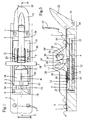
- the body of the fixing consists of a plate 1 having a thickness of about 2 cm, but in any case sufficient for it to be formed there two housings 2 and 3 of parallelepiped shape rectangular extending longitudinally one to the following each other over most of the length of plate 1 and separated by a wall 4 cut out.
- a thin plate 5 having a rectangular cutout 6 whose width is slightly less than the width of the housings 2 and 3 so as to form a T-profile slide.
- Such a slide would of course have been machined in plate 1, but in this case, it should have lead to at least one of the ends of the plate 1.
- the plate 1 is provided with four holes 7 for its fixation on a ski.
- the plate 1 also has, at one of its ends, a cylindrical axial hole 8 opening into part 2 of the slide (figure 2).
- part 2 of the slide two sliding pieces of rectangular shape 9 and 10.
- the part 10 constitutes a first retaining part provided a jaw 11 rising above the plate 1.
- the part 10 is hollowed out in its horizontal part of so as to form a recess 12 in which is sliding mounted piston 13 having two parallel cylindrical recesses such as the recess 14 ( Figure 3), recesses in which are housed respectively two identical parallel springs 15 and 16 working in compression between the bottom of the recess of part 12 and piston 13.
- Part 9 has a threaded axial hole 17 whose axis is located in the vertical plane of symmetry of the plate 1. This hole 17 is engaged on a screw 18 accessible by the hole 8 in the plate and which rests on the piston 13.
- a second part 19 also sliding in the slide and rectangular shape, of which rises a pair of parallel supports 20 to 21 located opposite the jaw 11.
- the part 19 presents further two threaded holes parallel to the axis of the slide such as hole 22 ( Figure 3). In these holes are screwed respectively the ends threaded with two tie rods 23 and 24 fitted with a head 25 by which these tie rods are supported on the part 9.
- the jaw 11 and the supports 20 and 21 define between them a transverse housing 26 having a notched profile ( Figures 2 and 3) running flaring in its upper part. On the side of the jaw 11, this profile has an oblique side 27 inclined towards the supports 20 and 21, while the opposite side 28 of the notch is rounded.
- a cam 29 in the form of heart suspended in its upper part around an axis transverse 30 carried by the supports 20 and 21 when the notch 26 is free, the cam 29 occupies, under the effect of its own weight and possibly a spring auxiliary, position 29 'shown in lines mixed, i.e. it enters the notch 26.
- the cam 29 enters the notch 26 from one side convex cylindrical 31.
- the plate 1 is also provided with one of its ends of a lever 32 articulated by means of a pin 33 transverse to the plate, in a notch 34 of the plate.
- a lever 32 articulated by means of a pin 33 transverse to the plate, in a notch 34 of the plate.
- a pull tab 36 whose bent end 37 is located, at rest, slightly in front of cam 29, at the limit of notch 26.
- the lever 32 is held in abutment against the top of the plate 1 by a spring not shown, for example a spring in hunting horn mounted around axis 33.
- This binding is intended to receive a shoe whose sole 42 is provided with a metal bar transverse cylindrical 38 in a central recess 39 of the sole by means of a metal stirrup.
- the bar diameter 38 is such that the part bottom of the profile of the housing 26 has a width substantially equal to the diameter of the bar 38. This width is substantially constant in the lower part of the notch 26 and increasing at the top.
- the cam 29 occupies the position 29 '.
- the bar 38 comes meet cam 29 and spread it effortlessly. Drug 29 then comes back to lean against the bar 38 as shown.
- a force upward pulling force exerted on the bar 38 tends to cause the cam 29 by friction and therefore reduce the width of notch 26 taking into account the eccentricity of the face 31 working the cam.
- Bar 38 is located by therefore retained in notch 26.
- the slope at point contact between cam 29 and bar 38 is strong enough to block the cam, but not strong enough for this blockage prevents easily separating the cam 29 from the bar 38 by the pull tab 36 by means of an action on the lever 32 as indicated by the arrow, figure 2. This action heaving takes place without stressing the springs 15 and 16.
- the precompression of springs 15 and 16, i.e. the hardness at the start of the fixation, can be adjusted using screw 18.
- the setting is displayed by an index 40 constituted, in the example shown, by a notch in the piston 13, this notch being visible through a slot 41 in part 10.
- parts 9 and 19 could be attached to plate 1, jaw 11 being only mobile in this case.
- the release lever 32 is located behind the plate, i.e. behind the shoe heel. However, everything could well heard to be inverted, the release lever being located in front of the plate, the position of the jaw 11 and the cam 29 being adapted accordingly.
- the second embodiment represented in FIG. 5, can be considered a variant of the first mode of execution.
- the transverse housing is here constituted two notches 50 and 51 formed by parts angled sides 52, 53 and 54, 55 of two plates 56 and 57 equivalent to parts 10 and 19 of the first mode of execution.
- On the bent parts 52 and 53 are mounted two cams 58 and 59 similar to cam 29 of the first mode of execution.
- the cams are articulated around an axis a and they are linked together by a bar 60 passing through the bent parts 52 and 53 by holes located at the bottom of the bent portions 52 and 53.
- This bar 60 also serves as an axis of rotation a release lever 61 biased by a spring in hunting horn tending to maintain the lever heaving in the lowered position as shown.
- the bar 60 On the side of the bent part 53, the bar 60 is bent twice and its end is engaged in a light 62 of cam 59.
- the spring of the release lever 61 therefore tends to keep the cam 59 lowered, as shown.
- the other cam 58 has a light similar to light 62 and in this light is engaged a finger secured to the lever 61 and playing the same rail as the angled end of bar 60. The cams are thus mechanically linked.
Applications Claiming Priority (2)
| Application Number | Priority Date | Filing Date | Title |
|---|---|---|---|
| FR9901328 | 1999-02-02 | ||
| FR9901328A FR2788992B1 (fr) | 1999-02-02 | 1999-02-02 | Ensemble chaussure-fixation de ski de securite |
Publications (2)
| Publication Number | Publication Date |
|---|---|
| EP1025882A1 true EP1025882A1 (de) | 2000-08-09 |
| EP1025882B1 EP1025882B1 (de) | 2004-09-01 |
Family
ID=9541626
Family Applications (1)
| Application Number | Title | Priority Date | Filing Date |
|---|---|---|---|
| EP00810076A Expired - Lifetime EP1025882B1 (de) | 1999-02-02 | 2000-01-27 | Sicherheitsskibindung-Schuh-Kombination |
Country Status (5)
| Country | Link |
|---|---|
| US (1) | US6412808B1 (de) |
| EP (1) | EP1025882B1 (de) |
| AT (1) | ATE274985T1 (de) |
| DE (1) | DE60013335T2 (de) |
| FR (1) | FR2788992B1 (de) |
Families Citing this family (4)
| Publication number | Priority date | Publication date | Assignee | Title |
|---|---|---|---|---|
| BRPI0518573A2 (pt) * | 2004-11-24 | 2008-11-25 | Dana Corp | mÉtodo para executar operaÇço de soldagem de pulso magnÉtico |
| FR2918573A1 (fr) * | 2007-07-10 | 2009-01-16 | Skis Rossignol Soc Par Actions | Arceau arrriere pour un dispositif de fixation de snowboard. |
| NO20101289A1 (no) * | 2010-09-15 | 2012-03-16 | Rottefella As | Langrennsbinding, samt fremgangsmate for sammenstilling av nevnte langrennsbinding |
| NO336669B1 (no) | 2012-11-19 | 2015-10-19 | Rottefella As | Skibinding |
Citations (5)
| Publication number | Priority date | Publication date | Assignee | Title |
|---|---|---|---|---|
| US4177584A (en) | 1977-03-28 | 1979-12-11 | Beyl Jean Joseph Alfred | Ski boot and binding assembly |
| US4182524A (en) | 1977-08-26 | 1980-01-08 | Look S.A. | Safety ski binding |
| EP0408824A2 (de) | 1989-07-21 | 1991-01-23 | Look S.A. | Skistiefel-Sicherheitsskibindungsanordnung |
| DE29608660U1 (de) * | 1995-05-16 | 1996-08-14 | Tyrolia Freizeitgeraete | Bindung und bzw. oder Schuh für Gleitbretter |
| WO1997022390A1 (fr) * | 1995-12-19 | 1997-06-26 | Societe Emery | Fixation de surf a neige a chaussage automatique et chaussure pour cette derniere |
Family Cites Families (12)
| Publication number | Priority date | Publication date | Assignee | Title |
|---|---|---|---|---|
| FR2332773A1 (fr) * | 1975-11-26 | 1977-06-24 | Salomon & Fils F | Fixation de securite pour chaussure de ski a rechaussage automatique |
| AT377185B (de) * | 1982-11-24 | 1985-02-25 | Tyrolia Freizeitgeraete | Sicherheitsskibindung |
| AT377705B (de) * | 1983-04-15 | 1985-04-25 | Tyrolia Freizeitgeraete | Sicherheitsskibindung, insbesondere fersenhalter |
| DE3405861C2 (de) * | 1983-12-16 | 1990-05-31 | Geze Gmbh, 7250 Leonberg | Langlauf- bzw. Wanderbindung |
| DE3437143C1 (de) * | 1984-10-10 | 1986-04-24 | Heinz 8391 Tiefenbach Beck | Auslöse- bzw. Sicherheitsabsatzhalterung für einen Skischuh |
| US4875724A (en) * | 1986-10-29 | 1989-10-24 | Magna International Inc. | Hood latch mechanism |
| DE3711284A1 (de) * | 1987-04-03 | 1988-10-13 | Heko Kunststofftechnik Gmbh | Schuhhalterung an einem alpin-surf-geraet |
| US5209530A (en) * | 1992-09-02 | 1993-05-11 | A. L. Hansen Mfg. Co. | Latch |
| US5505477A (en) * | 1993-07-19 | 1996-04-09 | K-2 Corporation | Snowboard binding |
| US5553697A (en) | 1995-06-15 | 1996-09-10 | Otis Elevator Company | Overlay for a passenger conveyor roller track |
| US6105996A (en) * | 1995-12-19 | 2000-08-22 | Emery S.A. | Shoe and binding of snowboard assembly |
| US5941553A (en) * | 1997-09-15 | 1999-08-24 | Korman; Nathan M. | Boot binding apparatus for a snowboard |
-
1999
- 1999-02-02 FR FR9901328A patent/FR2788992B1/fr not_active Expired - Fee Related
-
2000
- 2000-01-27 AT AT00810076T patent/ATE274985T1/de not_active IP Right Cessation
- 2000-01-27 EP EP00810076A patent/EP1025882B1/de not_active Expired - Lifetime
- 2000-01-27 DE DE60013335T patent/DE60013335T2/de not_active Expired - Fee Related
- 2000-01-31 US US09/495,287 patent/US6412808B1/en not_active Expired - Fee Related
Patent Citations (5)
| Publication number | Priority date | Publication date | Assignee | Title |
|---|---|---|---|---|
| US4177584A (en) | 1977-03-28 | 1979-12-11 | Beyl Jean Joseph Alfred | Ski boot and binding assembly |
| US4182524A (en) | 1977-08-26 | 1980-01-08 | Look S.A. | Safety ski binding |
| EP0408824A2 (de) | 1989-07-21 | 1991-01-23 | Look S.A. | Skistiefel-Sicherheitsskibindungsanordnung |
| DE29608660U1 (de) * | 1995-05-16 | 1996-08-14 | Tyrolia Freizeitgeraete | Bindung und bzw. oder Schuh für Gleitbretter |
| WO1997022390A1 (fr) * | 1995-12-19 | 1997-06-26 | Societe Emery | Fixation de surf a neige a chaussage automatique et chaussure pour cette derniere |
Also Published As
| Publication number | Publication date |
|---|---|
| FR2788992B1 (fr) | 2001-04-06 |
| FR2788992A1 (fr) | 2000-08-04 |
| DE60013335D1 (de) | 2004-10-07 |
| EP1025882B1 (de) | 2004-09-01 |
| DE60013335T2 (de) | 2005-09-01 |
| US6412808B1 (en) | 2002-07-02 |
| ATE274985T1 (de) | 2004-09-15 |
Similar Documents
| Publication | Publication Date | Title |
|---|---|---|
| EP0146454B1 (de) | Vorrichtung zum Festklemmen eines Schuhes an einem Fahrradpedal | |
| FR2750878A1 (fr) | Patin a roulettes en ligne | |
| EP1563876A1 (de) | Langlaufski | |
| EP0085313B1 (de) | Sicherheitsskibindung | |
| EP0771228B1 (de) | Bindung für einen schuh auf einem snowboard | |
| CH629107A5 (fr) | Fixation de securite pour ski comprenant un element de support d'une chaussure rotatif. | |
| EP2769755B1 (de) | Vordere Halteeinrichtung mit automatischer Auslösung bei Verdrehung | |
| EP0134595A1 (de) | Skischuh | |
| FR2646095A1 (fr) | Dispositif de fixation d'une paire de chaussures d'un skieur sur une planche de glisse sur neige | |
| WO2000029078A1 (fr) | Fixation de securite pour chaussure de ski | |
| EP0139815B1 (de) | Sicherheitsskibindung | |
| FR2788444A1 (fr) | Fixation declenchable pour planche de glisse | |
| EP0084813B1 (de) | Sicherheitsskibindung | |
| EP1025882B1 (de) | Sicherheitsskibindung-Schuh-Kombination | |
| EP1050326B1 (de) | Auslösbare Bindung für Gleitbrett | |
| EP0956886A1 (de) | Trägerplatte zwischen Schuh und Snowboard | |
| CH670203A5 (de) | ||
| EP0778056B1 (de) | Schuhrückhaltevorrichtung auf einem Snowboard bzw. Ski oder ähnlichem | |
| EP1027908A1 (de) | Rückhaltesystem für Schuhe auf Skier | |
| FR3098412A3 (fr) | Butée avant pour une fixation de ski de randonnée | |
| EP0332546A1 (de) | Bindung eines Schuhs auf einen Langlaufski | |
| FR2613949A1 (fr) | Dispositif de fixation de ski a chaussage automatique | |
| CH619144A5 (de) | ||
| FR2645036A1 (fr) | Dispositif de fixation d'une chaussure sur une planche de surf sur neige | |
| CH656542A5 (fr) | Fixation de securite pour ski. |
Legal Events
| Date | Code | Title | Description |
|---|---|---|---|
| PUAI | Public reference made under article 153(3) epc to a published international application that has entered the european phase |
Free format text: ORIGINAL CODE: 0009012 |
|
| AK | Designated contracting states |
Kind code of ref document: A1 Designated state(s): AT DE FR |
|
| AX | Request for extension of the european patent |
Free format text: AL;LT;LV;MK;RO;SI |
|
| 17P | Request for examination filed |
Effective date: 20000617 |
|
| AKX | Designation fees paid |
Free format text: AT DE FR |
|
| GRAP | Despatch of communication of intention to grant a patent |
Free format text: ORIGINAL CODE: EPIDOSNIGR1 |
|
| GRAS | Grant fee paid |
Free format text: ORIGINAL CODE: EPIDOSNIGR3 |
|
| GRAA | (expected) grant |
Free format text: ORIGINAL CODE: 0009210 |
|
| AK | Designated contracting states |
Kind code of ref document: B1 Designated state(s): AT DE FR |
|
| REF | Corresponds to: |
Ref document number: 60013335 Country of ref document: DE Date of ref document: 20041007 Kind code of ref document: P |
|
| PG25 | Lapsed in a contracting state [announced via postgrant information from national office to epo] |
Ref country code: AT Free format text: LAPSE BECAUSE OF NON-PAYMENT OF DUE FEES Effective date: 20050127 |
|
| PGFP | Annual fee paid to national office [announced via postgrant information from national office to epo] |
Ref country code: DE Payment date: 20050224 Year of fee payment: 6 |
|
| PLBE | No opposition filed within time limit |
Free format text: ORIGINAL CODE: 0009261 |
|
| STAA | Information on the status of an ep patent application or granted ep patent |
Free format text: STATUS: NO OPPOSITION FILED WITHIN TIME LIMIT |
|
| 26N | No opposition filed |
Effective date: 20050602 |
|
| PG25 | Lapsed in a contracting state [announced via postgrant information from national office to epo] |
Ref country code: DE Free format text: LAPSE BECAUSE OF NON-PAYMENT OF DUE FEES Effective date: 20060801 |
|
| PGFP | Annual fee paid to national office [announced via postgrant information from national office to epo] |
Ref country code: FR Payment date: 20061221 Year of fee payment: 8 |
|
| REG | Reference to a national code |
Ref country code: FR Ref legal event code: ST Effective date: 20081029 |
|
| PG25 | Lapsed in a contracting state [announced via postgrant information from national office to epo] |
Ref country code: FR Free format text: LAPSE BECAUSE OF NON-PAYMENT OF DUE FEES Effective date: 20080131 |