EP1025882A1 - Combined safety-ski-binding and boot - Google Patents
Combined safety-ski-binding and boot Download PDFInfo
- Publication number
- EP1025882A1 EP1025882A1 EP00810076A EP00810076A EP1025882A1 EP 1025882 A1 EP1025882 A1 EP 1025882A1 EP 00810076 A EP00810076 A EP 00810076A EP 00810076 A EP00810076 A EP 00810076A EP 1025882 A1 EP1025882 A1 EP 1025882A1
- Authority
- EP
- European Patent Office
- Prior art keywords
- cam
- bar
- assembly according
- parts
- shoe
- Prior art date
- Legal status (The legal status is an assumption and is not a legal conclusion. Google has not performed a legal analysis and makes no representation as to the accuracy of the status listed.)
- Granted
Links
Images


Classifications
-
- A—HUMAN NECESSITIES
- A63—SPORTS; GAMES; AMUSEMENTS
- A63C—SKATES; SKIS; ROLLER SKATES; DESIGN OR LAYOUT OF COURTS, RINKS OR THE LIKE
- A63C9/00—Ski bindings
- A63C9/08—Ski bindings yieldable or self-releasing in the event of an accident, i.e. safety bindings
- A63C9/086—Ski bindings yieldable or self-releasing in the event of an accident, i.e. safety bindings using parts which are fixed on the shoe of the user and are releasable from the ski binding
Definitions
- the present invention relates to a shoe-binding assembly triggerable ski in the event of a fall, too well in front or rear fall than in torsion, constituted a shoe, the sole of which is provided with a cross bar and a fixing having a longitudinal direction and a transverse direction and comprising means for retaining the boot by his bar.
- US Patent 4,177,584 shows a shoe provided with two transverse bars projecting laterally from the sole on each side of the shoe so that form two pairs of studs intended to be retained by two pairs of arms of a ski binding. This fixation is not described in this document, but it it appears from the drawings that a torsional release not possible.
- the above-mentioned safety fixings are also susceptible to snow accumulation which can easily prevent the fitting from fitting.
- the object of the invention is to produce an assembly ski boot-binding simpler than sets known from the prior art, not very sensitive to snow buildup in the binding and asking less effort for heaving.
- the ski boot-binding assembly is characterized in that the means for retaining the shoe located on the binding consist of, a part, of a transverse housing having a profile in notch-shaped and formed between two parts, one of which at least can be moved longitudinally against the action of at least one spring and, on the other hand, of a self-locking cam articulated around an axis transverse to the attachment to one of said parts and rotated by a spring tending to keep engaged in said housing, the shape of the surface of the cam intended to come into contact with the bar being such that the bar, once engaged in the housing, after removing the cam, has tendency to drag the cam by friction when a upward force is exerted on the bar, such so that the bar remains locked in the housing by jamming between the cam and the retaining part does not carrying the cam.
- the shoe is fitted with a single bar not protruding laterally from the sole and working in its middle area.
- the effort exerted on the bar has the effect of pushing back the moving parts based on the cam, as well in the case where the bar is stressed by a force directed upward only by a twisting force.
- a only relatively simple system therefore allows control both the triggering before falling or back than the torsional trigger.
- the shoe-binding assembly according to the invention is practically insensitive to snow accumulation in and on the fixing. A quick shoe is always possible.
- the shoe is effortless because it does not not accompanied by compression of the spring or trigger springs.
- the bar When putting on, the bar must simply spread the cam, possibly against the action of a weak spring of recall whose resistance is not always felt by the user.
- heaving is done by acting on the cam, that is to say by rotating it in the opposite direction to its blocking direction. In that case also, it is not necessary to compress the trigger spring.
- the two parts retaining means are movable longitudinally against the action of at least one spring common working in compression between two parts respectively secured to each of the two parts.
- the shoe release means are advantageously made up of a lever and an element connecting, such as a bent zipper at its end, allowing the cam to rotate in the direction opposite to its blocking direction.
- This lever can be hinged at the back or at the front of the binding for its actuation by hand or by means of a stick.
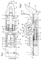
- the body of the fixing consists of a plate 1 having a thickness of about 2 cm, but in any case sufficient for it to be formed there two housings 2 and 3 of parallelepiped shape rectangular extending longitudinally one to the following each other over most of the length of plate 1 and separated by a wall 4 cut out.
- a thin plate 5 having a rectangular cutout 6 whose width is slightly less than the width of the housings 2 and 3 so as to form a T-profile slide.
- Such a slide would of course have been machined in plate 1, but in this case, it should have lead to at least one of the ends of the plate 1.
- the plate 1 is provided with four holes 7 for its fixation on a ski.
- the plate 1 also has, at one of its ends, a cylindrical axial hole 8 opening into part 2 of the slide (figure 2).
- part 2 of the slide two sliding pieces of rectangular shape 9 and 10.
- the part 10 constitutes a first retaining part provided a jaw 11 rising above the plate 1.
- the part 10 is hollowed out in its horizontal part of so as to form a recess 12 in which is sliding mounted piston 13 having two parallel cylindrical recesses such as the recess 14 ( Figure 3), recesses in which are housed respectively two identical parallel springs 15 and 16 working in compression between the bottom of the recess of part 12 and piston 13.
- Part 9 has a threaded axial hole 17 whose axis is located in the vertical plane of symmetry of the plate 1. This hole 17 is engaged on a screw 18 accessible by the hole 8 in the plate and which rests on the piston 13.
- a second part 19 also sliding in the slide and rectangular shape, of which rises a pair of parallel supports 20 to 21 located opposite the jaw 11.
- the part 19 presents further two threaded holes parallel to the axis of the slide such as hole 22 ( Figure 3). In these holes are screwed respectively the ends threaded with two tie rods 23 and 24 fitted with a head 25 by which these tie rods are supported on the part 9.
- the jaw 11 and the supports 20 and 21 define between them a transverse housing 26 having a notched profile ( Figures 2 and 3) running flaring in its upper part. On the side of the jaw 11, this profile has an oblique side 27 inclined towards the supports 20 and 21, while the opposite side 28 of the notch is rounded.
- a cam 29 in the form of heart suspended in its upper part around an axis transverse 30 carried by the supports 20 and 21 when the notch 26 is free, the cam 29 occupies, under the effect of its own weight and possibly a spring auxiliary, position 29 'shown in lines mixed, i.e. it enters the notch 26.
- the cam 29 enters the notch 26 from one side convex cylindrical 31.
- the plate 1 is also provided with one of its ends of a lever 32 articulated by means of a pin 33 transverse to the plate, in a notch 34 of the plate.
- a lever 32 articulated by means of a pin 33 transverse to the plate, in a notch 34 of the plate.
- a pull tab 36 whose bent end 37 is located, at rest, slightly in front of cam 29, at the limit of notch 26.
- the lever 32 is held in abutment against the top of the plate 1 by a spring not shown, for example a spring in hunting horn mounted around axis 33.
- This binding is intended to receive a shoe whose sole 42 is provided with a metal bar transverse cylindrical 38 in a central recess 39 of the sole by means of a metal stirrup.
- the bar diameter 38 is such that the part bottom of the profile of the housing 26 has a width substantially equal to the diameter of the bar 38. This width is substantially constant in the lower part of the notch 26 and increasing at the top.
- the cam 29 occupies the position 29 '.
- the bar 38 comes meet cam 29 and spread it effortlessly. Drug 29 then comes back to lean against the bar 38 as shown.
- a force upward pulling force exerted on the bar 38 tends to cause the cam 29 by friction and therefore reduce the width of notch 26 taking into account the eccentricity of the face 31 working the cam.
- Bar 38 is located by therefore retained in notch 26.
- the slope at point contact between cam 29 and bar 38 is strong enough to block the cam, but not strong enough for this blockage prevents easily separating the cam 29 from the bar 38 by the pull tab 36 by means of an action on the lever 32 as indicated by the arrow, figure 2. This action heaving takes place without stressing the springs 15 and 16.
- the precompression of springs 15 and 16, i.e. the hardness at the start of the fixation, can be adjusted using screw 18.
- the setting is displayed by an index 40 constituted, in the example shown, by a notch in the piston 13, this notch being visible through a slot 41 in part 10.
- parts 9 and 19 could be attached to plate 1, jaw 11 being only mobile in this case.
- the release lever 32 is located behind the plate, i.e. behind the shoe heel. However, everything could well heard to be inverted, the release lever being located in front of the plate, the position of the jaw 11 and the cam 29 being adapted accordingly.
- the second embodiment represented in FIG. 5, can be considered a variant of the first mode of execution.
- the transverse housing is here constituted two notches 50 and 51 formed by parts angled sides 52, 53 and 54, 55 of two plates 56 and 57 equivalent to parts 10 and 19 of the first mode of execution.
- On the bent parts 52 and 53 are mounted two cams 58 and 59 similar to cam 29 of the first mode of execution.
- the cams are articulated around an axis a and they are linked together by a bar 60 passing through the bent parts 52 and 53 by holes located at the bottom of the bent portions 52 and 53.
- This bar 60 also serves as an axis of rotation a release lever 61 biased by a spring in hunting horn tending to maintain the lever heaving in the lowered position as shown.
- the bar 60 On the side of the bent part 53, the bar 60 is bent twice and its end is engaged in a light 62 of cam 59.
- the spring of the release lever 61 therefore tends to keep the cam 59 lowered, as shown.
- the other cam 58 has a light similar to light 62 and in this light is engaged a finger secured to the lever 61 and playing the same rail as the angled end of bar 60. The cams are thus mechanically linked.
Abstract
Description
La présente invention concerne un ensemble chaussure-fixation de ski déclenchable en cas de chute, aussi bien en chute avant ou arrière qu'en torsion, constitué d'une chaussure dont la semelle est munie d'une barrette transversale et d'une fixation présentant une direction longitudinale et une direction transversale et comprenant des moyens de retenue de la chaussure par sa barrette.The present invention relates to a shoe-binding assembly triggerable ski in the event of a fall, too well in front or rear fall than in torsion, constituted a shoe, the sole of which is provided with a cross bar and a fixing having a longitudinal direction and a transverse direction and comprising means for retaining the boot by his bar.
Du brevet US 4 182 524, on connaít un ensemble chaussure-fixation dans lequel la chaussure est munie de deux barrettes faisant saillie de chaque côté de la chaussure de manière à former deux paires de tenons servant à la solidarisation de la chaussure à une plaque de la fixation, cette plaque étant elle-même montée sur un plot central sur lequel elle est retenue élastiquement en rotation par deux cadres rectangulaires prenant appui sur deux méplats opposés du plot central. Dans cet ensemble, les moyens de déclenchement, d'une part, en chute avant ou arrière et, d'autre part, en torsion, sont distincts l'un de l'autre et contrôlés chacun par leur propre dispositif élastique d'échappement. Cette fixation est relativement compliquée et les tenons forment des saillies peut judicieuses de chaque côté de la chaussure. En outre, le déchaussage nécessite la compression des ressorts de déclenchement retenant la chaussure sur la plaque, donc un effort considérable.From US patent 4,182,524, we know a set shoe-binding in which the shoe is provided two bars projecting from each side of the shoe so as to form two pairs of studs used to secure the shoe to a fixing plate, this plate itself mounted on a central stud on which it is retained elastically rotated by two frames rectangular supported on two opposite flats of the central stud. In this set, the means of triggering, on the one hand, falling forward or backward and, on the other hand, in torsion, are distinct one of each other and each controlled by their own device exhaust elastic. This fixation is relatively complicated and the studs form protrusions can make sense on either side of the shoe. In addition, heaving requires the compression of the trigger springs retaining the shoe on the plate, so a considerable effort.
De la demande de brevet EP 0 408 824, on connaít par ailleurs un ensemble chaussure-fixation dans lequel la chaussure est munie de deux plaques sensiblement verticales articulées autour de deux axes parallèles à la direction longitudinale de la chaussure, ces plaques coopérant avec des galets de retenue susceptibles de s'écarter l'un de l'autre lors du chaussage et en cas de chute avant ou arrière. Ces galets de retenue sont montés sur une plaque elle-même montée sur un plot central autour duquel la plaque peut pivoter en cas d'efforts de torsion, contre l'action de deux ressorts. Dans ce cas également, les moyens de déclenchement en chute avant ou arrière et en torsion sont des moyens distincts contrôlés par leur propre ressort et mécanisme associé. Pour déchausser volontairement, il est nécessaire d'écarter les plaques montées sur la chaussure, de telle sorte que les moyens d'actionnement de ces plaques sont également situés sur la chaussure, ce qui alourdit et complique la chaussure.From patent application EP 0 408 824, we know by elsewhere a shoe-binding assembly in which the shoe is provided with two substantially plates vertical articulated around two axes parallel to the longitudinal direction of the shoe, these plates cooperating with retaining rollers capable of move away from each other when putting on and in case front or rear fall. These retaining rollers are mounted on a plate itself mounted on a stud central around which the plate can pivot in case torsional forces, against the action of two springs. In this case also, the triggering means in fall forward or backward and twist are ways separate controlled by their own spring and associated mechanism. To remove shoes voluntarily, it it is necessary to separate the plates mounted on the shoe, so that the actuating means of these plates are also located on the shoe, which weighs down and complicates the shoe.
Le brevet US 4 177 584 montre une chaussure munie de deux barrettes transversales dépassant latéralement la semelle de chaque côté de la chaussure de manière à former deux paires de tenons destinés à être retenus par deux paires de bras d'une fixation de ski. Cette fixation n'est pas décrite dans ce document, mais il ressort des dessins qu'un déclenchement en torsion n'est pas possible.US Patent 4,177,584 shows a shoe provided with two transverse bars projecting laterally from the sole on each side of the shoe so that form two pairs of studs intended to be retained by two pairs of arms of a ski binding. This fixation is not described in this document, but it it appears from the drawings that a torsional release not possible.
De la demande de brevet internationale WO 97/223, on connaít par ailleurs une fixation de surf constituée d'un étrier muni de deux encoches dans lesquelles la barrette transversale équipant la chaussure vient se loger en écartant une paire de cames assurant un coincement automatique de la barrette dans les encoches. Cette fixation ne présente toutefois aucun moyen de libération de la chaussure en cas de chute et ce n'est donc pas une fixation de sécurité.From international patent application WO 97/223, it is also knows a surf binding made up a stirrup fitted with two notches in which the transverse bar fitted to the shoe comes accommodate by spreading a pair of cams ensuring a automatic clamping of the bar in the notches. However, this fixation has no means of release of the shoe in the event of a fall and it is therefore not a safety binding.
Les fixations de sécurité susmentionnées sont en outre sensibles à l'accumulation de neige qui peut facilement empêcher le chaussage de la fixation.The above-mentioned safety fixings are also susceptible to snow accumulation which can easily prevent the fitting from fitting.
L'invention a pour but de réaliser un ensemble chaussure-fixation de ski plus simple que les ensembles connus de l'art antérieur, peu sensible à l'accumulation de neige dans la fixation et demandant un effort moindre pour le déchaussage.The object of the invention is to produce an assembly ski boot-binding simpler than sets known from the prior art, not very sensitive to snow buildup in the binding and asking less effort for heaving.
L'ensemble chaussure-fixation de ski selon l'invention est caractérisé en ce que les moyens de retenue de la chaussure situés sur la fixation sont constitués, d'une part, d'un logement transversal présentant un profil en forme d'encoche et formé entre deux pièces dont l'une au moins est déplaçable longitudinalement contre l'action d'au moins un ressort et, d'autre part, d'une came auto-bloquante articulée autour d'un axe transversal à la fixation sur l'une desdites pièces et sollicitée en rotation par un ressort tendant à la maintenir engagée dans ledit logement, la forme de la surface de la came destinée à venir en contact avec la barrette étant telle que la barrette, une fois engagée dans le logement, après avoir écartée la came, a tendance à entraíner la came par frottement lorsqu'une force ascendante est exercée sur la barrette, de telle sorte que la barrette reste bloquée dans le logement par coincement entre la came et la pièce de retenue ne portant pas la came.The ski boot-binding assembly according to the invention is characterized in that the means for retaining the shoe located on the binding consist of, a part, of a transverse housing having a profile in notch-shaped and formed between two parts, one of which at least can be moved longitudinally against the action of at least one spring and, on the other hand, of a self-locking cam articulated around an axis transverse to the attachment to one of said parts and rotated by a spring tending to keep engaged in said housing, the shape of the surface of the cam intended to come into contact with the bar being such that the bar, once engaged in the housing, after removing the cam, has tendency to drag the cam by friction when a upward force is exerted on the bar, such so that the bar remains locked in the housing by jamming between the cam and the retaining part does not carrying the cam.
La chaussure est munie d'une seule barrette ne dépassant pas latéralement de la semelle et travaillant dans sa zone médiane. En cas de chute, l'effort exercé sur la barrette a pour effet de repousser la ou les pièces mobiles en s'appuyant sur la came, aussi bien dans le cas où la barrette est sollicitée par une force dirigée vers le haut que par une force de torsion. Un seul système, relativement très simple permet donc de contrôler aussi bien le déclenchement en chute avant ou arrière que le déclenchement en torsion.The shoe is fitted with a single bar not protruding laterally from the sole and working in its middle area. In the event of a fall, the effort exerted on the bar has the effect of pushing back the moving parts based on the cam, as well in the case where the bar is stressed by a force directed upward only by a twisting force. A only relatively simple system therefore allows control both the triggering before falling or back than the torsional trigger.
Etant donné que la came travaille en élément rattrapage de jeu et permet à la barrette d'être coincée à n'importe quelle hauteur sur une certaine plage, l'ensemble chaussure-fixation selon l'invention est pratiquement insensible à l'accumulation de neige dans et sur la fixation. Un chaussage rapide est toujours possible.Since the cam works as a take-up element and allows the bar to be stuck any height on a certain range, the shoe-binding assembly according to the invention is practically insensitive to snow accumulation in and on the fixing. A quick shoe is always possible.
Le chaussage se fait sans effort, car il ne s'accompagne pas d'une compression du ressort ou des ressorts de déclenchement. Lors du chaussage, la barrette doit simplement écarter la came, éventuellement contre l'action d'un faible ressort de rappel dont la résistance n'est dans tous les cas pas ressentie par l'utilisateur.The shoe is effortless because it does not not accompanied by compression of the spring or trigger springs. When putting on, the bar must simply spread the cam, possibly against the action of a weak spring of recall whose resistance is not always felt by the user.
De même, le déchaussage s'effectue en agissant sur la came, c'est-à-dire en faisant pivoter celle-ci dans le sens opposé à son sens de blocage. Dans ce cas également, il n'est pas nécessaire de comprimer le ressort de déclenchement.Similarly, heaving is done by acting on the cam, that is to say by rotating it in the opposite direction to its blocking direction. In that case also, it is not necessary to compress the trigger spring.
Selon un mode préféré de l'invention, les deux pièces des moyens de retenue sont déplaçables longitudinalement contre l'action d'au moins un ressort commun travaillant en compression entre deux parties respectivement solidaires de chacune des deux pièces.According to a preferred embodiment of the invention, the two parts retaining means are movable longitudinally against the action of at least one spring common working in compression between two parts respectively secured to each of the two parts.
Les moyens de libération de la chaussure sont avantageusement constitués d'un levier et d'un élément de liaison, tel qu'une tirette coudée à son extrémité, permettant d'entraíner la came en rotation dans le sens opposé à son sens de blocage. Ce levier peut être articulé à l'arrière ou à l'avant de la fixation pour son actionnement à la main ou au moyen d'un bâton.The shoe release means are advantageously made up of a lever and an element connecting, such as a bent zipper at its end, allowing the cam to rotate in the direction opposite to its blocking direction. This lever can be hinged at the back or at the front of the binding for its actuation by hand or by means of a stick.
Le dessin annexé représente, à titre d'exemple, deux
modes d'exécution de l'invention.
Dans le premier mode d'exécution le corps de la
fixation est constitué d'une plaque 1 présentant une
épaisseur d'environ 2 cm, mais dans tous les cas
suffisante pour qu'il puisse y être formé deux
logements 2 et 3 de forme parallélépipédique
rectangulaire s'étendant longitudinalement l'un à la
suite de l'autre sur la plus grande partie de la
longueur de la plaque 1 et séparés par une paroi 4
découpée. Sur la plaque 1 est fixée une mince plaque 5
présentant une découpe 6 rectangulaire dont la largeur
est légèrement inférieure à la largeur des logements 2
et 3 de manière à former une glissière à profil en T.
Un telle glissière aurait bien entendu peut être usinée
dans la plaque 1, mais dans ce cas, elle aurait dû
déboucher à l'une au moins des extrémités de la plaque
1. La plaque 1 est munie de quatre trous 7 pour sa
fixation sur un ski.In the first embodiment, the body of the
fixing consists of a plate 1 having a
thickness of about 2 cm, but in any case
sufficient for it to be formed there two
La plaque 1 présente en outre, à l'une de ses
extrémités, un trou axial cylindrique 8 débouchant dans
la partie 2 de la glissière (figure 2). The plate 1 also has, at one of its
ends, a cylindrical
Dans la partie 2 de la glissière, sont montées deux
pièces coulissantes de forme rectangulaires 9 et 10. La
pièce 10 constitue une première pièce de retenue munie
d'une mâchoire 11 s'élevant au dessus de la plaque 1.
La pièce 10 est évidée dans sa partie horizontale de
manière à former une creusure 12 dans laquelle est
monté coulissant un piston 13 présentant deux
évidements cylindriques parallèles tels que l'évidement
14 (figure 3), évidements dans lesquels sont logés
respectivement deux ressorts parallèles identiques 15
et 16 travaillant en compression entre le fond de la
creusure de la pièce 12 et le piston 13. La pièce 9
présente un trou axial fileté 17 dont l'axe est situé
dans le plan vertical de symétrie de la plaque 1. Ce
trou 17 est en prise sur une vis 18 accessible par le
trou 8 de la plaque et qui s'appuie sur le piston 13.In
Dans l'autre partie 3 de la glissière, est montée une
seconde pièce 19 également coulissante dans la
glissière et de forme rectangulaire, de laquelle
s'élève une paire de supports parallèles 20 à 21
situées en face de la mâchoire 11. La pièce 19 présente
en outre deux trous filetés parallèles à l'axe de la
glissière tels que le trou 22 (figure 3). Dans ces
trous sont vissées respectivement les extrémités
filetées de deux tirants 23 et 24 munis d'une tête 25
par laquelle ces tirants prennent appui sur la pièce 9.In the
On peut constater que la pièce coulissante 9 qui a
tendance à être repoussée par le piston 13 sous la
poussée des ressorts 15 et 16 est en fait retenue par
les tirants 23 et 24, lesquels sont eux-mêmes retenus
par la pièce coulissante 19 en butée contre la paroi
intermédiaire 4 de la glissière. Pour la même raison,
la pièce coulissante 10 est maintenue en appui contre
l'autre côté de cette paroi 4.We can see that the
La mâchoire 11 et les supports 20 et 21 définissent
entre eux un logement transversal 26 présentant un
profil en forme d'encoche (figures 2 et 3) allant en
s'évasant dans sa partie supérieure. Du côté de la
mâchoire 11, ce profil présente un côté oblique 27
incliné en direction des supports 20 et 21, tandis que
le côté opposé 28 de l'encoche est arrondi. Entre les
supports 20 et 21 est montée une came 29 en forme de
coeur suspendue en sa partie supérieure autour d'un axe
transversal 30 porté par les supports 20 et 21 lorsque
l'encoche 26 est libre, la came 29 occupe, sous l'effet
de son propre poids et éventuellement d'un ressort
auxiliaire, la position 29' représentée en traits
mixtes, c'est-à-dire qu'elle pénètre dans l'encoche 26.
La came 29 pénètre dans l'encoche 26 par une face
convexe cylindrique 31.The
La plaque 1 est en outre munie à l'une de ses
extrémités d'un levier 32 articulé au moyen d'un axe 33
transversal à la plaque, dans une encoche 34 de la
plaque. A ce levier 32 est attachée, en un point 35,
une tirette 36 dont l'extrémité coudée 37 est située,
au repos, légèrement en avant de la came 29, à la
limite de l'encoche 26. Dans cette position, le levier
32 est maintenu en butée contre le haut de la plaque 1
par un ressort non représenté, par exemple un ressort
en cor de chasse monté autour de l'axe 33. The plate 1 is also provided with one of its
ends of a
Cette fixation est destinée à recevoir une chaussure
dont la semelle 42 est munie d'une barrette métallique
transversale cylindrique 38 dans une creusure centrale
39 de la semelle au moyen d'un étrier métallique. Le
diamètre de la barrette 38 est tel que la partie
inférieure du profil du logement 26 présente une
largeur sensiblement égale au diamètre de la barrette
38. Cette largeur est sensiblement constante dans la
partie inférieure de l'encoche 26 et va en croissant
dans la partie supérieure.This binding is intended to receive a shoe
whose sole 42 is provided with a metal bar
transverse cylindrical 38 in a central recess
39 of the sole by means of a metal stirrup. The
Avant chaussage de la fixation, la came 29 occupe la
position 29'. Lors du chaussage, la barrette 38 vient
rencontrer la came 29 et l'écarte sans effort. La came
29 revient ensuite s'appuyer contre la barrette 38
comme représenté. Dans cette position, une force
d'arrachement dirigée vers le haut exercée sur la
barrette 38 a tendance à entraíner la came 29 par
frottement et par conséquent à réduire la largeur de
l'encoche 26 compte tenu de l'excentricité de la face
31 de travail de la came. La barrette 38 se trouve par
conséquent retenue dans l'encoche 26. La pente au point
de contact entre la came 29 et la barrette 38 est
suffisamment forte pour assurer un blocage de la came,
mais cependant pas assez forte pour que ce blocage
empêche d'écarter aisément la came 29 de la barrette 38
par la tirette 36 au moyen d'une action sur le levier
32 comme indiqué par la flèche, figure 2. Cette action
de déchaussage s'effectue sans solliciter les ressorts
15 et 16. Before fitting the binding, the
En cas de chute, c'est-à-dire d'effort sur la barrette
38 dépassant une certaine valeur, la barrette écarte la
mâchoire 11 et la came 29 l'une de l'autre en
comprimant les ressorts 15 et 16 et s'échappe de
l'encoche 26. Ceci peut se produire aussi bien en
raison d'efforts de traction situés dans un plan
passant par l'axe de la barrette que par un couple
ayant tendance à faire tourner la barrette dans un plan
horizontal. Le système étant en principe équilibré, les
deux pièces coulissantes 10 et 19 s'écartent toutes
deux de la nervure 4 et la pièce 9 est entraínée par la
pièce 19.In the event of a fall, i.e. effort on the
La précompression des ressorts 15 et 16, c'est-à-dire
la dureté au déclenchement de la fixation, peut être
réglée au moyen de la vis 18. Le réglage est affiché
par un index 40 constitué, dans l'exemple représenté,
par une encoche dans le piston 13, cette encoche étant
visible à travers une fente 41 de la pièce 10.The precompression of
Selon une variante d'exécution, les pièces 9 et 19
pourraient être fixées à la plaque 1, la mâchoire 11
étant seule mobile dans ce cas.According to an alternative embodiment,
Tel que représenté, le levier de déchaussage 32 est
situé en arrière de la plaque, c'est-à-dire derrière le
talon de la chaussure. Le tout pourrait toutefois bien
entendu être inversé, le levier de déchaussage étant
situé en avant de la plaque, la position de la mâchoire
11 et de la came 29 étant adaptée en conséquence. As shown, the
Le second mode d'exécution représenté à la figure 5,
peut être considéré comme une variante du premier mode
d'exécution. Le logement transversal est ici constitué
de deux encoches 50 et 51 formées par des parties
latérales coudées 52, 53 et 54, 55 de deux plaques 56
et 57 équivalentes aux pièces 10 et 19 du premier mode
d'exécution. Sur les parties coudées 52 et 53 sont
montées deux cames 58 et 59 analogues à la came 29 du
premier mode d'exécution. Les cames sont articulées
autour d'un axe a et elles sont liées entre elles par
une barre 60 traversant les parties coudées 52 et 53
par des trous situés au bas des parties coudées 52 et
53. Cette barre 60 sert également d'axe de rotation
d'un levier de déchaussage 61 sollicité par un ressort
en cor de chasse tendant à maintenir le levier de
déchaussage en position abaissée telle que représentée.
Du côté de la partie coudée 53, la barre 60 est coudée
deux fois et son extrémité est engagée dans une lumière
62 de la came 59. Le ressort du levier de déchaussage
61 a donc tendance à maintenir la came 59 abaissée,
comme représenté. L'autre came 58 présente une lumière
semblable à la lumière 62 et dans cette lumière est
engagé un doigt solidaire du levier 61 et jouant le
même râle que l'extrémité coudée de la barre 60. Les
cames sont ainsi mécaniquement liées.The second embodiment represented in FIG. 5,
can be considered a variant of the first mode
of execution. The transverse housing is here constituted
two
Pour déchausser, on soulève le levier 61 ce qui a pour
effet de faire pivoter les cames vers le bas et
d'ouvrir les encoches 50 et 51, libérant la barrette 38
retenue dans ce cas en deux endroits proches de ses
extrémités.To take off, the
Claims (14)
Applications Claiming Priority (2)
| Application Number | Priority Date | Filing Date | Title |
|---|---|---|---|
| FR9901328A FR2788992B1 (en) | 1999-02-02 | 1999-02-02 | SAFETY SKI SHOE-BINDING ASSEMBLY |
| FR9901328 | 1999-02-02 |
Publications (2)
| Publication Number | Publication Date |
|---|---|
| EP1025882A1 true EP1025882A1 (en) | 2000-08-09 |
| EP1025882B1 EP1025882B1 (en) | 2004-09-01 |
Family
ID=9541626
Family Applications (1)
| Application Number | Title | Priority Date | Filing Date |
|---|---|---|---|
| EP00810076A Expired - Lifetime EP1025882B1 (en) | 1999-02-02 | 2000-01-27 | Combined safety-ski-binding and boot |
Country Status (5)
| Country | Link |
|---|---|
| US (1) | US6412808B1 (en) |
| EP (1) | EP1025882B1 (en) |
| AT (1) | ATE274985T1 (en) |
| DE (1) | DE60013335T2 (en) |
| FR (1) | FR2788992B1 (en) |
Families Citing this family (4)
| Publication number | Priority date | Publication date | Assignee | Title |
|---|---|---|---|---|
| US20060131300A1 (en) * | 2004-11-24 | 2006-06-22 | Yablochnikov Boris A | Method for performing a magnetic pulse welding operation |
| FR2918573A1 (en) * | 2007-07-10 | 2009-01-16 | Skis Rossignol Soc Par Actions | REAR ARM FOR A SNOWBOARD FIXING DEVICE. |
| NO20101289A1 (en) * | 2010-09-15 | 2012-03-16 | Rottefella As | Cross-country bonding, as well as a method for assembling said cross-country bonding |
| NO336669B1 (en) | 2012-11-19 | 2015-10-19 | Rottefella As | Ski Binding |
Citations (5)
| Publication number | Priority date | Publication date | Assignee | Title |
|---|---|---|---|---|
| US4177584A (en) | 1977-03-28 | 1979-12-11 | Beyl Jean Joseph Alfred | Ski boot and binding assembly |
| US4182524A (en) | 1977-08-26 | 1980-01-08 | Look S.A. | Safety ski binding |
| EP0408824A2 (en) | 1989-07-21 | 1991-01-23 | Look S.A. | Ski boot safety binding |
| DE29608660U1 (en) * | 1995-05-16 | 1996-08-14 | Tyrolia Freizeitgeraete | Binding and / or shoe for gliding boards |
| WO1997022390A1 (en) * | 1995-12-19 | 1997-06-26 | Societe Emery | Self-coupling snowboard binding and footwear therefor |
Family Cites Families (12)
| Publication number | Priority date | Publication date | Assignee | Title |
|---|---|---|---|---|
| FR2332773A1 (en) * | 1975-11-26 | 1977-06-24 | Salomon & Fils F | SAFETY BINDING FOR AUTOMATIC SKI BOOTS |
| AT377185B (en) * | 1982-11-24 | 1985-02-25 | Tyrolia Freizeitgeraete | SAFETY SKI BINDING |
| AT377705B (en) * | 1983-04-15 | 1985-04-25 | Tyrolia Freizeitgeraete | SAFETY SKI BINDING, IN PARTICULAR HEEL REST |
| DE3405861C2 (en) * | 1983-12-16 | 1990-05-31 | Geze Gmbh, 7250 Leonberg | Cross-country skiing or hiking binding |
| DE3437143C1 (en) * | 1984-10-10 | 1986-04-24 | Heinz 8391 Tiefenbach Beck | Releasing and/or safety shoulder holding device for a ski boot |
| US4875724A (en) * | 1986-10-29 | 1989-10-24 | Magna International Inc. | Hood latch mechanism |
| DE3711284A1 (en) * | 1987-04-03 | 1988-10-13 | Heko Kunststofftechnik Gmbh | Shoe support on an alpine surfing apparatus |
| US5209530A (en) * | 1992-09-02 | 1993-05-11 | A. L. Hansen Mfg. Co. | Latch |
| US5505477A (en) * | 1993-07-19 | 1996-04-09 | K-2 Corporation | Snowboard binding |
| US5553697A (en) | 1995-06-15 | 1996-09-10 | Otis Elevator Company | Overlay for a passenger conveyor roller track |
| US6105996A (en) * | 1995-12-19 | 2000-08-22 | Emery S.A. | Shoe and binding of snowboard assembly |
| US5941553A (en) * | 1997-09-15 | 1999-08-24 | Korman; Nathan M. | Boot binding apparatus for a snowboard |
-
1999
- 1999-02-02 FR FR9901328A patent/FR2788992B1/en not_active Expired - Fee Related
-
2000
- 2000-01-27 AT AT00810076T patent/ATE274985T1/en not_active IP Right Cessation
- 2000-01-27 DE DE60013335T patent/DE60013335T2/en not_active Expired - Fee Related
- 2000-01-27 EP EP00810076A patent/EP1025882B1/en not_active Expired - Lifetime
- 2000-01-31 US US09/495,287 patent/US6412808B1/en not_active Expired - Fee Related
Patent Citations (5)
| Publication number | Priority date | Publication date | Assignee | Title |
|---|---|---|---|---|
| US4177584A (en) | 1977-03-28 | 1979-12-11 | Beyl Jean Joseph Alfred | Ski boot and binding assembly |
| US4182524A (en) | 1977-08-26 | 1980-01-08 | Look S.A. | Safety ski binding |
| EP0408824A2 (en) | 1989-07-21 | 1991-01-23 | Look S.A. | Ski boot safety binding |
| DE29608660U1 (en) * | 1995-05-16 | 1996-08-14 | Tyrolia Freizeitgeraete | Binding and / or shoe for gliding boards |
| WO1997022390A1 (en) * | 1995-12-19 | 1997-06-26 | Societe Emery | Self-coupling snowboard binding and footwear therefor |
Also Published As
| Publication number | Publication date |
|---|---|
| US6412808B1 (en) | 2002-07-02 |
| DE60013335T2 (en) | 2005-09-01 |
| EP1025882B1 (en) | 2004-09-01 |
| DE60013335D1 (en) | 2004-10-07 |
| FR2788992B1 (en) | 2001-04-06 |
| ATE274985T1 (en) | 2004-09-15 |
| FR2788992A1 (en) | 2000-08-04 |
Similar Documents
| Publication | Publication Date | Title |
|---|---|---|
| EP0146454B1 (en) | Device for attaching a cyclist's shoe to a bicycle pedal | |
| FR2750878A1 (en) | ONLINE SKATE SKATE | |
| EP1563876A1 (en) | Cross-country ski | |
| EP0085313B1 (en) | Safety ski binding | |
| EP0771228B1 (en) | Device for fixing a boot to a snowboard | |
| CH629107A5 (en) | SECURITY FIXATION FOR SKI COMPRISING A SUPPORT ELEMENT OF A ROTARY SHOE. | |
| EP2769755B1 (en) | Front unit with automatic triggering when twisted | |
| EP0134595A1 (en) | Ski boot | |
| FR2646095A1 (en) | DEVICE FOR FIXING A PAIR OF SHOES OF A SKIER ON A SNOWBOARD BOARD ON SNOW | |
| WO2000029078A1 (en) | Safety binding for ski boot | |
| EP0139815B1 (en) | Safety ski binding | |
| FR2788444A1 (en) | Releasable attachment for surf board has pair of jaws laterally separating by spring and additional jaw located in front or behind lateral jaws | |
| EP0084813B1 (en) | Safety ski binding | |
| EP1025882B1 (en) | Combined safety-ski-binding and boot | |
| EP1050326B1 (en) | Releasable fixation for a snowglider | |
| EP0956886A1 (en) | Interface between a boot and a snowboard | |
| CH670203A5 (en) | ||
| EP0778056B1 (en) | Device for retaining a boot on a snowboard, a ski or the like | |
| EP1027908A1 (en) | Heel-binding assembly for boots on skis | |
| FR3098412A3 (en) | Front stop for ski touring binding | |
| EP0332546A1 (en) | Shoe-binding on a cross-country-ski | |
| FR2613949A1 (en) | Ski-binding device with automatic fitting | |
| CH619144A5 (en) | ||
| FR2645036A1 (en) | Device for fastening a boot onto a snowboard | |
| CH656542A5 (en) | SECURITY FIXING FOR SKIING. |
Legal Events
| Date | Code | Title | Description |
|---|---|---|---|
| PUAI | Public reference made under article 153(3) epc to a published international application that has entered the european phase |
Free format text: ORIGINAL CODE: 0009012 |
|
| AK | Designated contracting states |
Kind code of ref document: A1 Designated state(s): AT DE FR |
|
| AX | Request for extension of the european patent |
Free format text: AL;LT;LV;MK;RO;SI |
|
| 17P | Request for examination filed |
Effective date: 20000617 |
|
| AKX | Designation fees paid |
Free format text: AT DE FR |
|
| GRAP | Despatch of communication of intention to grant a patent |
Free format text: ORIGINAL CODE: EPIDOSNIGR1 |
|
| GRAS | Grant fee paid |
Free format text: ORIGINAL CODE: EPIDOSNIGR3 |
|
| GRAA | (expected) grant |
Free format text: ORIGINAL CODE: 0009210 |
|
| AK | Designated contracting states |
Kind code of ref document: B1 Designated state(s): AT DE FR |
|
| REF | Corresponds to: |
Ref document number: 60013335 Country of ref document: DE Date of ref document: 20041007 Kind code of ref document: P |
|
| PG25 | Lapsed in a contracting state [announced via postgrant information from national office to epo] |
Ref country code: AT Free format text: LAPSE BECAUSE OF NON-PAYMENT OF DUE FEES Effective date: 20050127 |
|
| PGFP | Annual fee paid to national office [announced via postgrant information from national office to epo] |
Ref country code: DE Payment date: 20050224 Year of fee payment: 6 |
|
| PLBE | No opposition filed within time limit |
Free format text: ORIGINAL CODE: 0009261 |
|
| STAA | Information on the status of an ep patent application or granted ep patent |
Free format text: STATUS: NO OPPOSITION FILED WITHIN TIME LIMIT |
|
| 26N | No opposition filed |
Effective date: 20050602 |
|
| PG25 | Lapsed in a contracting state [announced via postgrant information from national office to epo] |
Ref country code: DE Free format text: LAPSE BECAUSE OF NON-PAYMENT OF DUE FEES Effective date: 20060801 |
|
| PGFP | Annual fee paid to national office [announced via postgrant information from national office to epo] |
Ref country code: FR Payment date: 20061221 Year of fee payment: 8 |
|
| REG | Reference to a national code |
Ref country code: FR Ref legal event code: ST Effective date: 20081029 |
|
| PG25 | Lapsed in a contracting state [announced via postgrant information from national office to epo] |
Ref country code: FR Free format text: LAPSE BECAUSE OF NON-PAYMENT OF DUE FEES Effective date: 20080131 |