EP1024561B1 - Verbinder und dessen Herstellungsverfahren - Google Patents
Verbinder und dessen Herstellungsverfahren Download PDFInfo
- Publication number
- EP1024561B1 EP1024561B1 EP00200296A EP00200296A EP1024561B1 EP 1024561 B1 EP1024561 B1 EP 1024561B1 EP 00200296 A EP00200296 A EP 00200296A EP 00200296 A EP00200296 A EP 00200296A EP 1024561 B1 EP1024561 B1 EP 1024561B1
- Authority
- EP
- European Patent Office
- Prior art keywords
- cover
- cable
- shielding
- connector
- ferrule
- Prior art date
- Legal status (The legal status is an assumption and is not a legal conclusion. Google has not performed a legal analysis and makes no representation as to the accuracy of the status listed.)
- Expired - Lifetime
Links
- 238000000034 method Methods 0.000 title claims description 27
- 239000004020 conductor Substances 0.000 claims abstract description 10
- HCHKCACWOHOZIP-UHFFFAOYSA-N Zinc Chemical compound [Zn] HCHKCACWOHOZIP-UHFFFAOYSA-N 0.000 claims description 4
- 238000002788 crimping Methods 0.000 claims description 4
- 229910052725 zinc Inorganic materials 0.000 claims description 4
- 239000011701 zinc Substances 0.000 claims description 4
- 238000005520 cutting process Methods 0.000 claims description 2
- 238000007747 plating Methods 0.000 claims description 2
- 230000003247 decreasing effect Effects 0.000 description 6
- 210000002105 tongue Anatomy 0.000 description 6
- 210000005069 ears Anatomy 0.000 description 3
- 238000004519 manufacturing process Methods 0.000 description 3
- PXHVJJICTQNCMI-UHFFFAOYSA-N Nickel Chemical compound [Ni] PXHVJJICTQNCMI-UHFFFAOYSA-N 0.000 description 2
- 238000009954 braiding Methods 0.000 description 2
- 230000007704 transition Effects 0.000 description 2
- RYGMFSIKBFXOCR-UHFFFAOYSA-N Copper Chemical compound [Cu] RYGMFSIKBFXOCR-UHFFFAOYSA-N 0.000 description 1
- ATJFFYVFTNAWJD-UHFFFAOYSA-N Tin Chemical compound [Sn] ATJFFYVFTNAWJD-UHFFFAOYSA-N 0.000 description 1
- 230000000712 assembly Effects 0.000 description 1
- 238000000429 assembly Methods 0.000 description 1
- 229910052802 copper Inorganic materials 0.000 description 1
- 239000010949 copper Substances 0.000 description 1
- 229910052751 metal Inorganic materials 0.000 description 1
- 239000002184 metal Substances 0.000 description 1
- 229910052759 nickel Inorganic materials 0.000 description 1
- 230000011664 signaling Effects 0.000 description 1
- 238000004381 surface treatment Methods 0.000 description 1
- 229910052718 tin Inorganic materials 0.000 description 1
- 239000011135 tin Substances 0.000 description 1
Images
Classifications
-
- H—ELECTRICITY
- H01—ELECTRIC ELEMENTS
- H01R—ELECTRICALLY-CONDUCTIVE CONNECTIONS; STRUCTURAL ASSOCIATIONS OF A PLURALITY OF MUTUALLY-INSULATED ELECTRICAL CONNECTING ELEMENTS; COUPLING DEVICES; CURRENT COLLECTORS
- H01R13/00—Details of coupling devices of the kinds covered by groups H01R12/70 or H01R24/00 - H01R33/00
- H01R13/648—Protective earth or shield arrangements on coupling devices, e.g. anti-static shielding
- H01R13/658—High frequency shielding arrangements, e.g. against EMI [Electro-Magnetic Interference] or EMP [Electro-Magnetic Pulse]
- H01R13/6591—Specific features or arrangements of connection of shield to conductive members
- H01R13/65912—Specific features or arrangements of connection of shield to conductive members for shielded multiconductor cable
-
- H—ELECTRICITY
- H01—ELECTRIC ELEMENTS
- H01R—ELECTRICALLY-CONDUCTIVE CONNECTIONS; STRUCTURAL ASSOCIATIONS OF A PLURALITY OF MUTUALLY-INSULATED ELECTRICAL CONNECTING ELEMENTS; COUPLING DEVICES; CURRENT COLLECTORS
- H01R13/00—Details of coupling devices of the kinds covered by groups H01R12/70 or H01R24/00 - H01R33/00
- H01R13/46—Bases; Cases
- H01R13/502—Bases; Cases composed of different pieces
-
- H—ELECTRICITY
- H01—ELECTRIC ELEMENTS
- H01R—ELECTRICALLY-CONDUCTIVE CONNECTIONS; STRUCTURAL ASSOCIATIONS OF A PLURALITY OF MUTUALLY-INSULATED ELECTRICAL CONNECTING ELEMENTS; COUPLING DEVICES; CURRENT COLLECTORS
- H01R13/00—Details of coupling devices of the kinds covered by groups H01R12/70 or H01R24/00 - H01R33/00
- H01R13/62—Means for facilitating engagement or disengagement of coupling parts or for holding them in engagement
- H01R13/621—Bolt, set screw or screw clamp
- H01R13/6215—Bolt, set screw or screw clamp using one or more bolts
-
- H—ELECTRICITY
- H01—ELECTRIC ELEMENTS
- H01R—ELECTRICALLY-CONDUCTIVE CONNECTIONS; STRUCTURAL ASSOCIATIONS OF A PLURALITY OF MUTUALLY-INSULATED ELECTRICAL CONNECTING ELEMENTS; COUPLING DEVICES; CURRENT COLLECTORS
- H01R13/00—Details of coupling devices of the kinds covered by groups H01R12/70 or H01R24/00 - H01R33/00
- H01R13/648—Protective earth or shield arrangements on coupling devices, e.g. anti-static shielding
- H01R13/658—High frequency shielding arrangements, e.g. against EMI [Electro-Magnetic Interference] or EMP [Electro-Magnetic Pulse]
- H01R13/6591—Specific features or arrangements of connection of shield to conductive members
- H01R13/6592—Specific features or arrangements of connection of shield to conductive members the conductive member being a shielded cable
- H01R13/6593—Specific features or arrangements of connection of shield to conductive members the conductive member being a shielded cable the shield being composed of different pieces
Definitions
- the present invention relates to a connector, in accordance with the preamble of claim 1, and a method, according to the preamble of claim 8, for assembling the connector.
- the two washers causes also a "step" to pass for the electrical signals, which causes ineffectiveness and reduction in performance, when used for high-speed signals.
- ferrules cause disturbances of the signals in the connection area between the shielding and the cover in the connector, that means that the electrical signals from the earth screen, have to go backward via a squeezed metal ferrule and furthermore forward to the cover of the connector.
- US 4 963 104 discloses a shielded connector assembly in which a double bushing, comprising an outer and an inner bushing, is used.
- the inner bushing has grooves which mate with ridges on the conductive inner surface of the connector half shells.
- Screws according to known technique, for fastening the connector to the rack have to be screwed through threads in the connector after the assembly process of the cable and the connector. This also causes a high mounting cost.
- an object of the invention to overcome the disadvantages of the known devices and methods. That is, primary, to decrease the assembling time and the complexity of the connector and furthermore to improve the electrical characteristics for shielding and grounding function.
- said ferrule (15) comprises first (17), second (19) and third (24) parts, wherein the first part (17) can be crimped onto said cable jacket (3) for fastening said connecting means (13) to said cable (3) and the second part (19) can be crimped onto said cable shielding (7) for electrical communication, and the third part (24) makes electrical contact with the cover means (11, 12, 14).
- the electrical signals can be transported in a substantially smooth and straight direction, that means that improved electrical characteristics for the shielding and grounding function have been provided. Furthermore the surface-treatment of the covers will be much easier, as there is no small slot in which the electrical connection takes place.
- the connecting means comprises an inner ferrule which can be fastened substantially under the shielding to the outer ferrule in the area of the second part for making an axial locking between the outer ferrule and the cover means by means of at least one holding member at the inner ferrule.
- the cable can be locked in an axial direction in relation to the connector.
- the at least one tongue member forming said third part at the end of said second part is in contact with said cover means, and which at least one tongue member is oriented in an elongated direction of said outer ferrule for making a smooth and straight member for electrical communication.
- the signals can have an even and direct way from the cable shielding to the cover halves and vice versa.
- the at least one holding member of the inner ferrule is locked in a recess of the outer ferrule and the cover for making the connecting means non-rotatably.
- the at least one holding member is arranged substantially normal to the width of said connector, which width then is minimized, for making space around said connector.
- Using bigger dimension of the cables leads to an improved signalling capacity.
- the cover means is made of zinc.
- a conductive material for the shielding and grounding function is provided.
- rivets are made integral with one of said cover means. This means that the assembly-time is decreased and that no mounting of the rivets to the cover halves is needed.
- the rivets may be cast integral with the cover.
- the connector is furthermore assembled by a method described below.
- the disadvantages of the known methods have been solved by a method as defined in the introduction, comprising the steps of fitting an outer ferrule onto the cable, stripping a part of the jacket of the cable, cutting a part of the shielding for providing the shielding substantially the length of a second part of the outer ferrule, fitting an inner ferrule over the at least one conductor and under the shielding, sliding the outer ferrule back over the inner ferrule within the area of the second part, crimping the outer ferrule onto the inner ferrule, thereby trapping the cable shielding and making an electrical connection to the ferrules, and onto the cable jacket at the same time or substantially at the same time, terminating the at least one conductor into the terminal block, mounting the terminal block with the fitted cable and ferrules into the bottom cover and mounting the top cover to the bottom cover.
- the assembly-time for the assembly is decreased compared with known assemblies, due to that the crimping can be done in one step.
- the mounting of at least two screws into said bottom cover takes place before fitting said top cover to said bottom cover.
- the threads of the screws have also a function of stopping the screws to fall out during transport.
- the assembly-time is additionally decreased compared with known methods.
- said top cover is fitted to said bottom cover by means of deforming the head of rivets, which are integrated in the bottom or top cover.
- the rivets may be cast integral with the cover. This means that the assembly-time is further decreased.
- the integrated rivets leads to that the manufacturing of the cover and rivets is more uncomplicated, since no mounting of the rivets to the halves has to be done. Further more it is easier fitting the two cover halves together, since the rivets already are in their position.
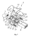
- a connector 9 for connection to a cable 3, with a number of conductors 5 within a, for example, braided shielding 7, a connector 9 comprises first and second cover halves 12, 14, which are designed for electrical communication.
- the cover halves 12, 14 can be made of zinc. They are designed for making a connection between a connection means 13, which, according to the invention, is an outer ferrule 15, which is in contact with the braided shielding 7 of the cable 3, and a socket (not shown) in a rack (not shown).
- the surfaces 11 of the cover halves 12, 14 can be made even and smooth, with no slots or other sharp members in the electrical path.
- the cover halves 12, 14 are in figure 1 mechanically connectable to a terminal block 8.
- the connector comprises furthermore an inner ferrule 21, which is located under the shielding 7 of the cable 3, that is between the shielding 7 and the conductors 5.
- the shielding 7 is illustrated in a cut of the jacket 4.
- a first part 17 is crimped onto the jacket 4 of the cable 3 and a second part 19 is crimped onto the shielding 7. That means that the jacket 4 is stripped in the area of the second part 19 for making a contact with the shielding 7.
- the outer ferrule 15 is accordingly to the invention during the assembly process at the same time crimped onto the jacket 4 of the cable 3 and onto respectively the shielding 7 and the inner ferrule 21 with respectively the first part 17 and the second part 19 of the outer ferrule 15.
- the inner ferrule 21 is provided with at least one lug 23.
- the inner ferrule 21 is here provided with two lugs 23, which each are located in a recess 25 at the end of the second part 19 of the outer ferrule 15 and in the cover.
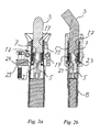
- the lugs 23 are in the figure 1 and 2b, seen as illustrated, arranged in a vertical direction in relation to the width for decreasing the width of the connector 9. If the lugs 23 should be arranged horizontally, the height could be decreased instead.
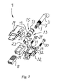
- the top cover 14 and a bottom cover 12 have a surface 11 (shown in fig. 3) inside for electrical communication.
- the surface 11 could be zinc with a suitable plating (for example copper, nickel, tin etc).
- the outer ferrule 15 has to be in contact with the surface 11. This is made by means of springing tongues 24 of the outer ferrule 15, which are in contact with the surface 11 of the first and second cover halves 12, 14.
- Screws 29, 30, each provided with a threaded and an unthreaded part are located in respectively two ear halves 31, 32 before fitting the top cover 14 to the bottom cover 12. This means that no threads in the ears 31, 32 have to be done. This means that the strength of the ears can be increased, as the ears 31, 32 can be made thicker.
- rivets 34 are made in one part with the bottom cover 12. This means that the assembly process can be done more easily than before, since no external rivets have to be pre-mounted in the bottom cover 12 before fitting the bottom cover 12 to the top cover 14.
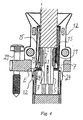
- Figure 4 illustrates the above described example of the invention, in which parts denoted with a reference sign correspond to parts described in figure 1, 2a, 2b and 3.
- Figure 4 shows by means of an arrow E schematically the smooth and substantial straight path of the electrical signal flow from the braided shielding 7 to the two cover halves 12, 14.
- the springing tongues 24 By means of the springing tongues 24, a contact between the outer ferrule 15 and the braided shielding 7 and the cover halves 12, 14 is provided. This means that an electrical communication can take place between the shielding 7 and the cover 12 via the outer ferrule 15 and its springing tongues 24. As the springing tongues 24 have their location in the extension length of the outer ferrule 15, the communication can take place without making any sharp and abrupt transition section.
- Known technique means that the electrical signals have to made a sharp and abrupt transition way in the area between the shielding and the cover.
- Today used spring washers cause a sharp path for the signals.
- known ferrules causes a non-smooth communication between the shielding and the surface of the cover halves or the cover. It is according to known technique a problem for the surface to have an even thickness all over the area for electrical communication.
- Known technique means that the crimping operation, during the assembling process, of the ferrules to the jacket must be done in two steps.
- the electrical signals can make a smooth and straight path. This leads to an improved electrical performance for, for example, the shielding and the grounding function.
- the inner ferrule is provided with a member for preventing a rotation of the cable. This member also locks the cable in an axial direction. Also may hooks, arranged to the cover, be used for hooking the outer ferrule to the cover.
- the covers may be made with rounded external corners. This will, while plaiting the cables with associated connectors, make the plaiting easier to control, since the covers will not damage each other during, for example, a trumbeling process.
Landscapes
- Details Of Connecting Devices For Male And Female Coupling (AREA)
- Multi-Conductor Connections (AREA)
- Coupling Device And Connection With Printed Circuit (AREA)
Claims (9)
- Verbinder für ein Kabel (3) mit mindestens einem Leiter (5) und einer Schutzhülle (7), wobei der Verbinder (9) Deckelmittel (11, 12, 14), wobei die Deckelmittel Deckelhälften (12, 14) aufweisen und eine Fläche (11) zur elektrischen Übertragung haben, und eine Anschlusseinrichtung (13) aufweist, die mit der Schutzhülle (7) und den Deckelhälften (12, 14) verbunden werden kann, wobei die Anschlusseinrichtung (13) einen Außenring (15) aufweist, dadurch gekennzeichnet, dass der Ring (15) einen ersten (17), zweiten (19) und dritten (24) Teil aufweist, wobei der erste Teil (17) zur Befestigung der Anschlusseinrichtung (13) am Kabel (3) auf den Kabelmantel (4) gecrimpt werden kann, und der zweite Teil (19) zur elektrischen Verbindung auf die Kabelschutzhülle (7) gecrimpt werden kann und der dritte Teil (24) elektrischen Kontakt mit den Deckelmitteln (11, 12, 14) herstellt.
- Verbinder nach Anspruch 1, wobei die Anschlusseinrichtung (13) außerdem einen Innenring (21) aufweist, der im Wesentlichen unter der Schutzhülle (7) am Außenring (15) im Bereich des zweiten Teils (19) befestigt ist, um eine axiale Verriegelung zwischen dem Außenring (15) und den Deckelmitteln (11, 12, 14) mit Hilfe mindestens eines Halteelements (23) am Innenring (21) durchzuführen.
- Verbinder nach Anspruch 1, wobei mindestens ein Zungenelement (24), das den dritten Teil am Ende des zweiten Teils (19) bildet, mit den Deckelmitteln (11, 12, 14) in Kontakt steht und wobei das mindestens eine Zungenelement (24) in Längsrichtung des Außenrings (15) ausgerichtet ist, um ein glattes und gerades Element für die elektrische Verbindung zu bilden.
- Verbinder nach Anspruch 2, wobei mindestens ein Halteelement (23) des Innenrings (21) in einer Vertiefung (25) des Außenrings (15) und der Deckelmittel (11, 12, 14) verriegelt ist, um zu erreichen, dass die Anschlusseinrichtung (13) nicht drehbar ist.
- Verbinder nach Anspruch 2 oder 4, wobei mindestens ein Halteelement (23) im Wesentlichen senkrecht zur Breite des Verbinders (9) angeordnet ist, dessen Breite dann minimiert wird, um um den Verbinder (9) herum Platz zu schaffen.
- Verbinder nach einem der vorstehenden Ansprüche, wobei die Deckelmittel (11, 12, 14) aus Zink mit geeigneter Beschichtung bestehen.
- Verbinder nach einem der vorstehenden Ansprüche, wobei Nieten (34) in eines der Deckelmittel (11, 12, 14) eingebaut sind.
- Verfahren zum Zusammenbau eines Kabels (3) mit einem Verbinder (9) nach Anspruch 1, wobei das Kabel (3) mindestens einen Leiter (5) und eine Schutzhülle (7) aufweist, und wobei der Verbinder (9) Deckelmittel (11, 12, 14), die für die elektrische Verbindung bestimmt sind und einen unteren Deckel (12), einen oberen Deckel (14) und eine Fläche (11) besitzen, einen Anschlussblock (8) und eine Verbindungseinrichtung (13) aufweist, die mit der Schutzhülle (7) und den Deckelmitteln (11, 12, 14) verbindbar ist, wobei das Verfahren die Schritte des Befestigens eines Außenrings (15) auf dem Kabel (3), des Entfernens eines Teils des Mantels (4) vom Kabel (3), des Abschneidens eines Teils der Schutzhülle, um die Schutzhülle (7) im Wesentlichen über die Länge eines zweiten Teils (19) des Außenrings (15) zu liefern, des Befestigens eines Innenrings (21) über dem mindestens einen Leiter (5) und unter der Schutzhülle (7), des Zurückschiebens des Außenrings (15) über den Innenring (21) im Bereich des zweiten Teils (19), des Crimpens des Außenrings (15) auf den Innenring (21), zum Festklemmen der Kabelschutzhülle (7) und zur Herstellung einer elektrischen Verbindung mit den Ringen (15, 21), und gleichzeitig, oder im Wesentlichen gleichzeitig, auf den Kabelmantel (4), des Anschließens des mindestens einen Leiters (5) im Anschlussblock (8), des Einsetzens des Anschlussblocks (8) mit dem befestigten Kabel (3) und den Ringen (15, 21) in den unteren Deckel (12) und des Aufsetzens des oberen Deckels (14) auf den unteren Deckel (12) aufweist.
- Verfahren nach Anspruch 8, das den Schritt des Einsetzens von mindestens zwei Schrauben (29, 30) in den unteren Deckel (12) enthält, ehe der obere Deckel (14) am unteren Deckel (12) befestigt wird.
Applications Claiming Priority (2)
| Application Number | Priority Date | Filing Date | Title |
|---|---|---|---|
| SE9900299A SE520444C2 (sv) | 1999-01-29 | 1999-01-29 | Kontaktdon och metod för ihopsättning av kontaktdonet |
| SE9900299 | 1999-01-29 |
Publications (3)
| Publication Number | Publication Date |
|---|---|
| EP1024561A2 EP1024561A2 (de) | 2000-08-02 |
| EP1024561A3 EP1024561A3 (de) | 2000-08-09 |
| EP1024561B1 true EP1024561B1 (de) | 2003-10-01 |
Family
ID=20414289
Family Applications (1)
| Application Number | Title | Priority Date | Filing Date |
|---|---|---|---|
| EP00200296A Expired - Lifetime EP1024561B1 (de) | 1999-01-29 | 2000-01-28 | Verbinder und dessen Herstellungsverfahren |
Country Status (5)
| Country | Link |
|---|---|
| US (1) | US6203377B1 (de) |
| EP (1) | EP1024561B1 (de) |
| AT (1) | ATE251349T1 (de) |
| DE (1) | DE60005577T2 (de) |
| SE (1) | SE520444C2 (de) |
Families Citing this family (17)
| Publication number | Priority date | Publication date | Assignee | Title |
|---|---|---|---|---|
| US6338645B1 (en) * | 2000-07-28 | 2002-01-15 | Apple Computer, Inc. | Connector having a cable that is relatively moveable about an axis |
| NL1022159C2 (nl) * | 2002-12-13 | 2004-06-15 | Framatome Connectors Int | Kabelconnector en methode voor het vervaardigen van een kabelconnector. |
| NL1022225C2 (nl) * | 2002-12-20 | 2004-06-22 | Framatome Connectors Int | Kabelconnector en werkwijze voor het samenvoegen van een kabel en een dergelijke kabelconnector. |
| TW573839U (en) * | 2003-06-27 | 2004-01-21 | Hon Hai Prec Ind Co Ltd | Cable connector assembly |
| US7083472B2 (en) | 2004-06-10 | 2006-08-01 | Commscope Solutions Properties, Llc | Shielded jack assemblies and methods for forming a cable termination |
| US7033219B2 (en) * | 2004-06-10 | 2006-04-25 | Commscope Solutions Properties, Llc | Modular plug assemblies, terminated cable assemblies and methods for forming the same |
| NL1026451C2 (nl) * | 2004-06-18 | 2005-12-20 | Framatome Connectors Int | Kabelconnector en werkwijze voor het assembleren van een kabel en een dergelijke kabelconnector. |
| JP4909793B2 (ja) * | 2007-04-18 | 2012-04-04 | 住友電装株式会社 | シールドコネクタ |
| EP2343783A1 (de) | 2008-11-06 | 2011-07-13 | Hon Hai Precision Industry Co., Ltd. | Kabelendenverbindungsanordnung |
| DE202009015571U1 (de) * | 2009-11-14 | 2011-03-24 | Wieland Electric Gmbh | Elektrischer Steckverbinder |
| CN102340081B (zh) * | 2010-07-16 | 2014-12-24 | 富士康(昆山)电脑接插件有限公司 | 线缆连接器组件 |
| US9124008B2 (en) * | 2013-08-29 | 2015-09-01 | Tyco Electronics Corporation | Electrical connector |
| JP6610954B2 (ja) * | 2016-06-01 | 2019-11-27 | 住友電装株式会社 | シールドコネクタ |
| CN106785591B (zh) * | 2017-01-23 | 2019-09-03 | 中航光电科技股份有限公司 | 一种屏蔽套及使用该屏蔽套的连接器 |
| CN108413158B (zh) * | 2018-04-10 | 2019-06-28 | 东北大学 | 一种用于大电流的气(液)电一体化快速连接装置及方法 |
| CN111342309A (zh) * | 2018-12-18 | 2020-06-26 | 广东皓英电子科技有限公司 | 线缆连接器 |
| JP7206906B2 (ja) * | 2018-12-28 | 2023-01-18 | 株式会社オートネットワーク技術研究所 | 端子モジュールおよびコネクタ |
Family Cites Families (14)
| Publication number | Priority date | Publication date | Assignee | Title |
|---|---|---|---|---|
| US4194805A (en) * | 1973-03-28 | 1980-03-25 | Bunker Ramo Corporation | Electrical contacting element |
| DE8109532U1 (de) | 1981-03-31 | 1981-08-13 | Adolf Strobel Antennenfabrik GmbH & Co KG, 5060 Bergisch Gladbach | Verbinder für ein Koaxialkabel |
| GB2097601B (en) | 1981-04-27 | 1985-02-27 | Fleetwood Electrics Ltd | Cord grips for electrical plugs or appliances especially for non-rewirable plugs |
| US4640569A (en) * | 1985-03-27 | 1987-02-03 | Amp Incorporated | Adaptor for coupling a cable to a connector |
| JPH0530307Y2 (de) * | 1987-02-12 | 1993-08-03 | ||
| JPH01177883U (de) | 1988-06-04 | 1989-12-19 | ||
| US4963104A (en) * | 1989-05-01 | 1990-10-16 | Spark Innovations, Inc. | Shielded connector assembly |
| US5267878A (en) * | 1990-03-05 | 1993-12-07 | Yazaki Corporation | Electrical connector for shielding cable |
| US5180316A (en) * | 1991-03-25 | 1993-01-19 | Molex Incorporated | Shielded electrical connector |
| JP3673527B2 (ja) * | 1993-04-30 | 2005-07-20 | 矢崎総業株式会社 | シールド電線接続用端子 |
| US5460544A (en) * | 1993-05-26 | 1995-10-24 | Yazaki Corporation | Electro-magnetically shielded connector |
| JP2868973B2 (ja) * | 1993-06-08 | 1999-03-10 | 矢崎総業株式会社 | シールドコネクタ |
| US5823803A (en) * | 1996-06-17 | 1998-10-20 | Conxall Corporation | Electrical cable connector |
| GB9619552D0 (en) | 1996-09-19 | 1996-10-30 | Itt Ind Ltd | Coaxial connector body |
-
1999
- 1999-01-29 SE SE9900299A patent/SE520444C2/sv unknown
-
2000
- 2000-01-28 US US09/494,157 patent/US6203377B1/en not_active Expired - Lifetime
- 2000-01-28 DE DE60005577T patent/DE60005577T2/de not_active Expired - Lifetime
- 2000-01-28 EP EP00200296A patent/EP1024561B1/de not_active Expired - Lifetime
- 2000-01-28 AT AT00200296T patent/ATE251349T1/de not_active IP Right Cessation
Also Published As
| Publication number | Publication date |
|---|---|
| DE60005577D1 (de) | 2003-11-06 |
| EP1024561A3 (de) | 2000-08-09 |
| US6203377B1 (en) | 2001-03-20 |
| DE60005577T2 (de) | 2004-08-05 |
| ATE251349T1 (de) | 2003-10-15 |
| SE9900299L (sv) | 2000-07-30 |
| SE9900299D0 (sv) | 1999-01-29 |
| SE520444C2 (sv) | 2003-07-08 |
| EP1024561A2 (de) | 2000-08-02 |
Similar Documents
| Publication | Publication Date | Title |
|---|---|---|
| EP1024561B1 (de) | Verbinder und dessen Herstellungsverfahren | |
| US6705894B1 (en) | Shielded electrical connector | |
| US7033219B2 (en) | Modular plug assemblies, terminated cable assemblies and methods for forming the same | |
| EP2642600B1 (de) | Selbstblockierender Koaxialkabelverbinder mit Erdungsaufrechterhaltung | |
| EP1641089B1 (de) | Steckverbinder mit Kontakten die in einem angepassten isolierenden Gehäuse montiert sind | |
| AU2005255867C1 (en) | Shielded jack assemblies and methods for forming a cable termination | |
| EP0907221B1 (de) | Elektrischer Kabelsteckverbinder | |
| EP2451017B1 (de) | Elektrische Steckverbinderanordnung | |
| US5711686A (en) | System for terminating the shield of a high speed cable | |
| US4386819A (en) | RF Shielded assembly having capacitive coupling feature | |
| EP1944837A1 (de) | Anschluss für Potenzialausgleich | |
| DE112018001914B4 (de) | Innenleiteranschluss und abgeschirmter Verbinder | |
| US5046967A (en) | Electrical connector shell including plastic and metal portions, and method of assembly | |
| EP1608045B1 (de) | Abgeschirmter Verbinder und Verbindungsverfahren mit einem abgeschirmten Leiterbahn | |
| DE19848411B4 (de) | Abgeschirmter Stecker | |
| US7857663B2 (en) | Connector assemblies, combinations and methods for use with foil-shielded twisted pair cables | |
| DE102016210044A1 (de) | Verbinder und Verfahren zum Fertigen eines Verbinders | |
| DE69321683T2 (de) | Abgeschirmter Verbinder zur Datenübertragung | |
| US4662700A (en) | Metal backshell and method of assembling same | |
| AU2016404931B2 (en) | Modular plug provided with metal shielding cover, and communication cable | |
| DE112019006501B4 (de) | Anschlussmodul und Verbinder | |
| KR102878604B1 (ko) | 데이터 전송 모듈 | |
| EP4485710A1 (de) | Abgeschirmte keystone-stanzwinde | |
| US20240243524A1 (en) | Shielded keystone style punchdown jack | |
| GB2232540A (en) | Electrical screen connectors |
Legal Events
| Date | Code | Title | Description |
|---|---|---|---|
| PUAI | Public reference made under article 153(3) epc to a published international application that has entered the european phase |
Free format text: ORIGINAL CODE: 0009012 |
|
| PUAL | Search report despatched |
Free format text: ORIGINAL CODE: 0009013 |
|
| AK | Designated contracting states |
Kind code of ref document: A2 Designated state(s): AT BE CH CY DE DK ES FI FR GB GR IE IT LI LU MC NL PT SE |
|
| AX | Request for extension of the european patent |
Free format text: AL;LT;LV;MK;RO;SI |
|
| AK | Designated contracting states |
Kind code of ref document: A3 Designated state(s): AT BE CH CY DE DK ES FI FR GB GR IE IT LI LU MC NL PT SE |
|
| AX | Request for extension of the european patent |
Free format text: AL;LT;LV;MK;RO;SI |
|
| 17P | Request for examination filed |
Effective date: 20010105 |
|
| 17Q | First examination report despatched |
Effective date: 20010226 |
|
| AKX | Designation fees paid |
Free format text: AT BE CH CY DE DK ES FI FR GB GR IE IT LI LU MC NL PT SE |
|
| GRAH | Despatch of communication of intention to grant a patent |
Free format text: ORIGINAL CODE: EPIDOS IGRA |
|
| GRAH | Despatch of communication of intention to grant a patent |
Free format text: ORIGINAL CODE: EPIDOS IGRA |
|
| GRAA | (expected) grant |
Free format text: ORIGINAL CODE: 0009210 |
|
| AK | Designated contracting states |
Kind code of ref document: B1 Designated state(s): AT BE CH CY DE DK ES FI FR GB GR IE IT LI LU MC NL PT SE |
|
| PG25 | Lapsed in a contracting state [announced via postgrant information from national office to epo] |
Ref country code: IT Free format text: LAPSE BECAUSE OF FAILURE TO SUBMIT A TRANSLATION OF THE DESCRIPTION OR TO PAY THE FEE WITHIN THE PRESCRIBED TIME-LIMIT;WARNING: LAPSES OF ITALIAN PATENTS WITH EFFECTIVE DATE BEFORE 2007 MAY HAVE OCCURRED AT ANY TIME BEFORE 2007. THE CORRECT EFFECTIVE DATE MAY BE DIFFERENT FROM THE ONE RECORDED. Effective date: 20031001 Ref country code: BE Free format text: LAPSE BECAUSE OF FAILURE TO SUBMIT A TRANSLATION OF THE DESCRIPTION OR TO PAY THE FEE WITHIN THE PRESCRIBED TIME-LIMIT Effective date: 20031001 Ref country code: NL Free format text: LAPSE BECAUSE OF FAILURE TO SUBMIT A TRANSLATION OF THE DESCRIPTION OR TO PAY THE FEE WITHIN THE PRESCRIBED TIME-LIMIT Effective date: 20031001 Ref country code: CY Free format text: LAPSE BECAUSE OF FAILURE TO SUBMIT A TRANSLATION OF THE DESCRIPTION OR TO PAY THE FEE WITHIN THE PRESCRIBED TIME-LIMIT Effective date: 20031001 Ref country code: CH Free format text: LAPSE BECAUSE OF FAILURE TO SUBMIT A TRANSLATION OF THE DESCRIPTION OR TO PAY THE FEE WITHIN THE PRESCRIBED TIME-LIMIT Effective date: 20031001 Ref country code: FI Free format text: LAPSE BECAUSE OF FAILURE TO SUBMIT A TRANSLATION OF THE DESCRIPTION OR TO PAY THE FEE WITHIN THE PRESCRIBED TIME-LIMIT Effective date: 20031001 Ref country code: AT Free format text: LAPSE BECAUSE OF FAILURE TO SUBMIT A TRANSLATION OF THE DESCRIPTION OR TO PAY THE FEE WITHIN THE PRESCRIBED TIME-LIMIT Effective date: 20031001 Ref country code: LI Free format text: LAPSE BECAUSE OF FAILURE TO SUBMIT A TRANSLATION OF THE DESCRIPTION OR TO PAY THE FEE WITHIN THE PRESCRIBED TIME-LIMIT Effective date: 20031001 |
|
| REG | Reference to a national code |
Ref country code: GB Ref legal event code: FG4D |
|
| REG | Reference to a national code |
Ref country code: CH Ref legal event code: EP |
|
| REG | Reference to a national code |
Ref country code: IE Ref legal event code: FG4D |
|
| REF | Corresponds to: |
Ref document number: 60005577 Country of ref document: DE Date of ref document: 20031106 Kind code of ref document: P |
|
| PG25 | Lapsed in a contracting state [announced via postgrant information from national office to epo] |
Ref country code: GR Free format text: LAPSE BECAUSE OF FAILURE TO SUBMIT A TRANSLATION OF THE DESCRIPTION OR TO PAY THE FEE WITHIN THE PRESCRIBED TIME-LIMIT Effective date: 20040101 Ref country code: SE Free format text: LAPSE BECAUSE OF FAILURE TO SUBMIT A TRANSLATION OF THE DESCRIPTION OR TO PAY THE FEE WITHIN THE PRESCRIBED TIME-LIMIT Effective date: 20040101 Ref country code: DK Free format text: LAPSE BECAUSE OF FAILURE TO SUBMIT A TRANSLATION OF THE DESCRIPTION OR TO PAY THE FEE WITHIN THE PRESCRIBED TIME-LIMIT Effective date: 20040101 |
|
| PG25 | Lapsed in a contracting state [announced via postgrant information from national office to epo] |
Ref country code: ES Free format text: LAPSE BECAUSE OF FAILURE TO SUBMIT A TRANSLATION OF THE DESCRIPTION OR TO PAY THE FEE WITHIN THE PRESCRIBED TIME-LIMIT Effective date: 20040112 |
|
| PG25 | Lapsed in a contracting state [announced via postgrant information from national office to epo] |
Ref country code: IE Free format text: LAPSE BECAUSE OF NON-PAYMENT OF DUE FEES Effective date: 20040128 Ref country code: LU Free format text: LAPSE BECAUSE OF NON-PAYMENT OF DUE FEES Effective date: 20040128 |
|
| PG25 | Lapsed in a contracting state [announced via postgrant information from national office to epo] |
Ref country code: MC Free format text: LAPSE BECAUSE OF NON-PAYMENT OF DUE FEES Effective date: 20040131 |
|
| NLV1 | Nl: lapsed or annulled due to failure to fulfill the requirements of art. 29p and 29m of the patents act | ||
| REG | Reference to a national code |
Ref country code: CH Ref legal event code: PL |
|
| ET | Fr: translation filed | ||
| PLBE | No opposition filed within time limit |
Free format text: ORIGINAL CODE: 0009261 |
|
| STAA | Information on the status of an ep patent application or granted ep patent |
Free format text: STATUS: NO OPPOSITION FILED WITHIN TIME LIMIT |
|
| 26N | No opposition filed |
Effective date: 20040702 |
|
| REG | Reference to a national code |
Ref country code: IE Ref legal event code: MM4A |
|
| PGFP | Annual fee paid to national office [announced via postgrant information from national office to epo] |
Ref country code: GB Payment date: 20050126 Year of fee payment: 6 |
|
| PG25 | Lapsed in a contracting state [announced via postgrant information from national office to epo] |
Ref country code: GB Free format text: LAPSE BECAUSE OF NON-PAYMENT OF DUE FEES Effective date: 20060128 |
|
| GBPC | Gb: european patent ceased through non-payment of renewal fee |
Effective date: 20060128 |
|
| PG25 | Lapsed in a contracting state [announced via postgrant information from national office to epo] |
Ref country code: PT Free format text: LAPSE BECAUSE OF NON-PAYMENT OF DUE FEES Effective date: 20040301 |
|
| REG | Reference to a national code |
Ref country code: FR Ref legal event code: CA Ref country code: FR Ref legal event code: TP |
|
| REG | Reference to a national code |
Ref country code: FR Ref legal event code: PLFP Year of fee payment: 17 |
|
| PGFP | Annual fee paid to national office [announced via postgrant information from national office to epo] |
Ref country code: FR Payment date: 20151230 Year of fee payment: 17 |
|
| REG | Reference to a national code |
Ref country code: FR Ref legal event code: ST Effective date: 20170929 |
|
| PG25 | Lapsed in a contracting state [announced via postgrant information from national office to epo] |
Ref country code: FR Free format text: LAPSE BECAUSE OF NON-PAYMENT OF DUE FEES Effective date: 20170131 |
|
| PGFP | Annual fee paid to national office [announced via postgrant information from national office to epo] |
Ref country code: DE Payment date: 20190129 Year of fee payment: 20 |
|
| REG | Reference to a national code |
Ref country code: DE Ref legal event code: R071 Ref document number: 60005577 Country of ref document: DE |